The restyled model of the GAZ 31105 car replaced the GAZ 3110 in 2004. The new car has undergone significant changes, but much remains from its predecessor. In particular, the ZMZ 402 and ZMZ 406 engines were installed on the new Volga from the very beginning.
Engine ZMZ 402 cross-section
Subsequently, the line of engines for the 31105 changed - since 2006, the “one hundred and fifth” models with a 2.4-liter Chrysler engine were introduced into the series, and a 2.5-liter ZMZ 405 power unit was also added.
Engines of GAZ-A and GAZ-AA cars
GAZ-A passenger cars and GAZ-AA trucks received the same Ford engine. Nothing surprising: let us remember that the first lorry and a half from modern history, the Gazelles, in the 90s, shared their power units with the Volga-31029.
The licensed Ford engine, which was given to Soviet cars in the 30s, was far from perfect not only from the standpoint of today, but even in the pre-war years.
The crankshaft of this four-cylinder unit was mounted on only three support bearings, and did not have counterweights to reduce vibration levels. Therefore, the emphasis was placed on a massive flywheel, which was additionally loaded by the clutch and could not, of course, not transfer increased dynamic load to the rear support bearing of the crankshaft. And the main and connecting rod bearings did not, as they do now, have thin-walled replaceable liners to increase the maintainability of motors, but were filled with babbitt, and then required processing locally to the size of the journals of a particular shaft.
For comparison, let us recall how the Soviet four-cylinder GAZ-25 engine was made, almost the same dimensions. This 1944 model engine received a four-bearing crankshaft. The crank of the first cylinder was located between the first and second bearing journals of the crankshaft, the crank of the fourth cylinder was located between the third and fourth bearings, respectively. And between the second and third support journals, the cranks of the second and third cylinders and a common central balancer rotated. Due to this arrangement of the crank mechanism, the weight of the flywheel was reduced to a minimum, and the loads on the main bearings were distributed more evenly.
The GAZ-25 power unit, after changes in the lubrication system, was subsequently redesignated as M-20, and was known as the engine for the Pobeda and GAZ-69 vehicles.
The gas distribution mechanism of the lorry did not have the ability to adjust the gaps in the valves, which were selected initially, or worked from repair to repair, with all the known consequences due to the resulting incorrect gaps.
Lubrication under pressure, as such, practically did not exist; the performance of the oil pump was only sufficient to provide supply with a slight excess pressure (0.8 - 1.5 atm on a warm engine) to the support bearings of the crankshaft and camshaft, and the connecting rod bearings were lubricated " by self-scooping”, clinging in the lower position to the level of oil poured into the crankcase.
The piston group and cylinders were lubricated by the same splashing. There were no oil filters, there was only a mesh on the oil receiver, and factory requirements for changing the oil every 800-1000 km. mileage If any of the readers does not believe that the lorry engines did without filters at all, then in the proposed diagram of the oil circulation in the engine, he still will not find them.
The oil pressure was not monitored in any way; by unscrewing the plug in the oil line, the driver could only make sure that the pump was working and there was still some kind of oil supply.
The cooling systems of these pre-war engines are thermosiphon type, with water circulation due to expansion when heated. And a small “exciting” pump only initiated the beginning of this circulation. There were no blinds, thermostats, or water temperature control devices.
The K-14 carburetor, similar to the American Zenit, was mounted under the intake manifold, and had an “upward” mixture flow, only due to the vacuum in the cylinders. There was no fuel pump - the supply was carried out by gravity, fortunately, the 40-liter fuel tank was located above the carburetor, actually in the engine compartment.
But, be that as it may, this is exactly the engine that the lorry had from 1932 to 1938. This power unit, with a cylinder diameter of 98.43 mm. with a working volume of 3.28 liters and a compression ratio of 4.2, developed 42 hp. at 2600 rpm, and torque 15.5 kgm at 1200 rpm. /min.
In 1935, on the eve of the start of production of the GAZ-M1 passenger car (1936), the engine was somewhat modernized. An increased compression ratio to 4.6 made it possible to increase power to 50 hp. at 2800 rpm, and torque up to 17 kgm at 1450 rpm. This engine featured a fuel pump (in the Emka the gas tank was located under the rear overhang), a new ignition distributor with a centrifugal advance machine, as well as a connection from the oil line to the pressure gauge in the cabin of the passenger car.
But, as mentioned above, the lorry did not immediately receive an engine with increased power. And the “modernization” was good (as indicated by the letter “M”), if the truck’s engine did not receive an updated set of attachments! And their drivers were still left without oil pressure control, and with the only possible manual adjustment of the ignition timing. There would be a fuel pump, like that of an Emka, a GAZ-MM semi-truck, and a gas tank under the body, of a larger volume - with a standard 40-liter tank you won’t run over much. But it was not supposed to: make do, driver, with what you have, you are not the first!
In 1941, the engine of the GAZ-MM truck, produced since 1938, was again modernized. But only... for installation on army command jeeps GAZ-64 (later GAZ-67). The power unit received an increased capacity water pump for forced water circulation, an ignition distributor with a centrifugal advance machine, and a K-23 carburetor with a “falling” mixture flow, which made it possible to increase power to 54 hp. Only the lorry drivers, as before, remained in their own interests...
ZMZ 406
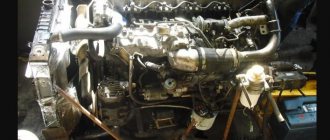
By the time the ZMZ 406 engine appeared on the Volga 31105, it had already been well tested on the previous model 3110, and had proven itself mainly on the positive side. ICE 406 began to be installed as standard on the Volga 3110 since 1997, and with a smaller volume (2.3 liters) it had more power and better torque. True, due to the presence of an electronic control system, the ZMZ 406 added new problems - sensors and ECUs often failed, breaks and short circuits occurred in the engine compartment wiring.
This is what a ZMZ 406 engine ready for installation looks like.
Some malfunctions could be identified by error codes when the ignition is turned on, but the average vehicle user was unable to figure out the electronics on their own.
Diagnostics are mainly carried out by Volga car owners with the 406th engine at a specialized service station. The 406th had its own “sores”:
- Chains and other parts of the gas distribution mechanism wore out relatively quickly;
- The hydraulic timing chain tensioners often jammed;
- Electric remote fuel pumps periodically failed;
- At the slightest overheating, the head gasket burned out, and the head itself often warped.
The design of the ZMZ has not thought through the design of the timing chain tension. The extension of the upper chain shoe has a large load and often breaks off.
Timing chain on a ZMZ 406 engine
Breaking it off causes a lot of problems:
- Firstly, its remains have to be drilled out of the cylinder block;
- Secondly, the chains break, and labor-intensive repairs have to be made.
Transmission of GAZ-AA and GAZ-MM cars
The clutch of GAZ-AA and GAZ-MM cars is dry, single-disk, with a mechanical lever drive. The clutch did not have its own housing, and therefore during installation it was installed on an open flywheel, which was then covered with a housing made integral with the gearbox housing.
Four-speed gearboxes, with spur gears, without synchronizers, had the following gear ratios: 1. - 6.40; 2.- 3.09; 3. – 1.69; 4.- 1.00; Z.H. – 7.82. Later, these units were taken as the basis for gearboxes for GAZ-61, -64, -67 jeeps, and post-war GAZ-51 and GAZ-63 trucks.
Thanks to the ingenuity of front-line drivers, a “fifth speed” appeared on lorries. It was a stick with a spear at the end, broken from a branch of a suitable tree. It was placed in a space between the gearshift lever in the fourth speed position and the bulkhead of the engine compartment. This solved the problem of constant “knocking out” of the direct transmission while the car was moving when parts of the secondary shaft of the gearbox wore out. And ZIS truck drivers, meanwhile, made do with only four gearbox speeds initially provided for by the design of these vehicles.
The big problem with the maintainability of these trucks was the design of their driveshafts. The transmission had a single hinge that made it possible to transmit torque at a varying angle. This hinge connected the output (secondary) shaft of the gearbox with the drive shaft of the rear axle. The drive shaft of the rear axle was installed in a closed pipe, rigidly connected to the final drive housing. And the compression and recoil of the rear axle suspension was compensated only by the longitudinal splined connection of the drive shaft inside the pipe. Therefore, in case of malfunctions or wear of the only hinge, it was necessary to remove it from the springs, unhook it from the reaction and brake rods, and “roll” back the entire rear axle.
If it was necessary to repair the clutch, everything was even more complicated. The already mentioned driveshaft pipe, which rested on the rear axle, did not allow removing the gearbox by moving it back as expected. And as the reader guesses, there was only one and diametrically opposite way out - to remove the entire power unit, the engine along with the gearbox, forward.
The figure below shows an image of the cardan transmission, final drive, axle shafts and wheel hubs of a GAZ-A passenger car. The fundamental difference between this combination of units in a semi-truck is in the size of the parts, the shape and structure of the final drive housing. The mutual arrangement and arrangement of all parts that transmit forces to the wheels are the same for GAZ trucks and passenger cars of the 30s.
Position 5 in the figure is the only drive shaft joint that transmits forces at a changing angle.
But the rear axle of the car, as such, was not a gift, and implied considerable problems for operators and repairmen.
The main gear with a 6.60 gearbox did not contribute to the thrust-to-weight ratio of these machines, with their 40-50-horsepower engines. Let us remember that in the GAZ-51 with a 70-horsepower engine, the rear axle gearbox had an even higher ratio (6.67).
The one and a half axle had axle shafts, unloaded by ¾, and forged together with the differential gears. What did this mean? When assembling this unit, first both axle shafts were assembled into a single unit, together with the differential box of the main gear. Then, the axle shaft casings were “slipped” onto this unit from both sides. And then, on the ends of these axle shafts, wheel hubs were installed on a conical fit, which were secured against turning with keys, and against loosening of the mutual conical connection - with cotter nuts.
The hubs did not rotate on double tapered roller bearings, with the possibility of adjusting them as they wear out, as now, but on single cylindrical bearings, without the possibility of adjusting the preload.
Well, as the reader understands, by definition the axle shafts were not removed from the outside; if one of them broke, the entire bridge had to be removed and completely disassembled. And hubs that have “boiled” on their conical-keyed fit cannot be removed without a special puller or heating by gas welding “once”. This is not an axle shaft of a completely unloaded type, like the ZIS-5 or GAZ-51, which can be taken out by simply screwing in two bolts with M 12 threads...
But that's not all. What is the difference between fully unloaded axle shafts, say, from a GAZ-51 or ZIS-5, and axle axles from a lorry, unloaded by ¾? The fact that in the first case, the hub at the end of the bridge beam has a fastening independent of the axle shaft, and the breakdown of the latter does not affect the fastening of the hub and wheels.
And if the driver does not have another axle shaft with him, the car is simply taken to the “tie” or to the “fork” and performs the duties of a trailer for some time. And in a semi-truck, the hub of the rear wheels stays in place only as long as the axle shaft is intact. And in another case, friction in the roller bearing of the hub alone will not keep it from falling out along with the wheel onto the road. Back then, a “ski” was brought under the broken end of the bridge, but in the days of lorries, not every truck was capable of dragging such a “plow”. Well, as you know, tractors don’t go long distances...
We come to another section highlighting the miscalculations of the pro-American design embodied in the Soviet car.
Tuning 402 engine
Considering the age of the engine and modern increased needs, one can understand why many craftsmen are trying to improve the engine. "Volga-402" is a fairly old modification, I would like to update it. What can be done? More power is what the 402 engine needs. “Gazelle” and “Volga” will benefit significantly from this. There are several options for such tuning.
One of them is boring the block for larger diameter sleeves. If the original 402 block has sleeves 92 mm in diameter, then the bored one has all 100 mm, just like on the modern UMZ-4216. In this case, new sleeves are also installed in 100 mm sizes. The main disadvantage of such an upgrade is the deterioration of the thermal conditions of the cylinder block. After all, the walls became thinner by the size of the groove. And this is as much as 4 mm.
In another embodiment, the increase in power is ensured by grinding the block head. At the same time, the compression ratio increases, which allows you to switch to gasoline with a higher octane number. You can also increase the diameter of the exhaust pipe and slightly widen the exhaust manifold. All this will give the necessary plus 5-10 liters. With.
The most noticeable increase in power is up to plus 30 hp. With. – is replacing the carburetor with an injector. True, this is a rather troublesome and expensive procedure.
Chassis GAZ-AA
At the beginning of the material there was already a mention that both lorry pendants were not a gift for our transport workers. The front suspension of the GAZ-AA, and others like it, included a single transverse spring and a so-called spacer fork - two reaction rods that converged in a V - shape, from both ends of the front axle beam, to the hinge of their fastening in the middle part of the frame.
These reaction rods prevented the ends of the beam from moving back and forth in the longitudinal axis of the machine. And the semi-elliptical spring, rigidly fixed with a “hump” upward in its middle in the front of the car, and hinged to the ends of the front axle beam, did not allow the latter to move left or right.
But, as any person understands, such a suspension in plan was not a very rigid triangle, in fact, with two (!) attachment points in the longitudinal axis of the car.
If one of the longitudinal springs breaks in the trucks we are used to, then the vehicle, getting a roll on one side, does not lose the ability to continue moving. In addition, a savvy driver can also build a spacer between the frame spar and the axle beam to level out the roll. But what to do with a single broken transverse spring, and in a situation where the front axle beam begins to “walk” even more to the left and right?
The rear suspensions of the GAZ-AA and GAZ-MM vehicles are made on two cantilever-type longitudinal springs. The spring packages of such suspensions are attached to the frame with their hump upwards on the swing axes, like the balancer suspensions of three-axle vehicles. The front ends of such packages, with the help of earrings, are hinged and also attached to the frame side members. And the rear beam is attached to the rear cantilever and downward-pointing ends of the springs. This axle also has reaction rods.
What do we see? The fact that the rear shoulders of the springs have a deliberately larger range of bending angles than the front ones means that the springs perceive an uneven load along their entire length. What do we know from history? The fact that when reversing, with random but strong impacts with the rear wheel on an obstacle (a stump from a tree, falling into a hole), the suspension “twisted”, the springs broke, and the reaction rods bent. Why be surprised? The springs and thrust rods actually received a blow to the butt, which they were not designed for. For more or less smooth work in tension - compression, and an axial impact - are far from the same thing. It is no coincidence that on GAZ-51 cars, which were built on the same (if not even worse immediately after the war) roads, there were no such solutions. Neither the front nor the rear suspensions.
In the photo we see a stuck semi-truck in a generally harmless situation - the wheels did not fall into a hole, the bridge beams did not bury themselves in the ground.
A lorry with a tarnished reputation
Having carefully examined the situation, with a high degree of probability we can assume that the car “sat” on the reaction rods of the front or rear suspension, or was caught by the hinge of the front axle spacer fork. Otherwise, why would you try to place supports under the front, non-driving wheels? And if it was just a matter of the rear wheels sliding, why not just try to rock the truck back and forth “from the pusher”? However, if the first assumption is still true, then you can immediately make the second - if this “lawn” had four normal longitudinal springs, like the same age as the ZIS-5, or the successor to the GAZ-51, such situations might not have happened in principle ...
By the way, there are cases where semi-trucks were forced, or when the opportunity arose, to be converted to the “fifty-first” speed. With the installation of post-war spring suspensions, and with the “rolling in” of new bridges.
The author of these lines, in 1997, personally repaired such a truck. It was a vehicle of the military-patriotic search group “Crew” (leader S.N. Tsvetkov, died in 2001). It, already converted (with a GAZ-51 engine and gearbox), was found by the Tsvetkovites in one of the collapsed farms in the Russian outback. And now, probably, this car is in the museum of technology of Vadim Zadorozhny, (village Ilinskoye, Krasnogorsk district, Moscow region) And if any of the readers see it there, they will be able to make sure, at least by the 6-stud fastening of the wheels - semi-trucks “a la GAZ-51” existed.
There is a photo of another similar machine on the Internet. We see wheels from GAZ-51, which cannot be installed on the axle hubs of a semi-truck.
And enlarging the image clearly shows that the rear axle from the GAZ-51 is also installed. It is given out by a “cylindrical” hub with a fully balanced axle flange. In addition, an attentive and knowledgeable reader will also notice a package of post-war springs, “stepped” down.
But why all this, if GAZ-MM cars were produced until the mid-50s, and there were enough original spare parts for less labor costs for ordinary repairs compared to re-equipment? After all, making such changes to a state or collective farm truck is not at all like installing a Volga engine or rear axle on a personal Pobeda...
The GAZ-AA and GAZ-MM vehicles had identical wheels with tire sizes of 6.50 x 20 inches and five-window rims. The reader, having carefully examined the wheels in the photo on the intro to the material, can agree with us that the rims of the trucks, due to such window sizes, could be structurally weakened. This fact may directly or indirectly be evidenced by the following fact.
Divisional, 76 mm. The ZIS-3 gun, which went through the entire war on tires and 5-stud front hubs from a GAZ-AA truck, had its own, 2-window wheel rims. So the problem asks: was it worth changing the technology for producing wheel rims from a semi-truck, given almost the same load on these parts? For the ZIS-3 gun, its total weight (1200 kg) was distributed over two single-wheel drive wheels. And for a loaded semi, the total weight falling on the rear axle (2485 kg) was distributed over two double ramps.
There is enough photographic evidence on the Internet that light and delicate rims of one and a half cars were sometimes consigned to the dustbin of history. And instead of them, 2-window disks from the same ZIS-3 guns, or mobile compressor stations of the PKS-5 type were used.
By the way, if the reader is not aware, then the first GAZ-51 cars, until the early 50s, had 2-window rims from the ZIS-5, although the designers, of course, already knew 6-window rims from “ Studebakers."
Truly, as the saying goes, “When you get burned on milk, you blow on water.”
What other evidence is needed that the lorry’s “running”, despite all their military and labor services to the party and the state, was “Third class - not a waste”?
We believe that an objective reader will agree with us: when considering the designs of even well-known and honored front-line vehicles, one must be able to see all of them (if any), shortcomings and miscalculations. And not to “cover” them with bullet and shrapnel holes in the wings and cockpits.
By the way, according to some information we have, there was an opinion among front-line drivers who drove domestic cars. In a critical combat situation, those who rode a ZIS-5 rather than a “lawn” had a greater chance of surviving. And on front-line “plowed” roads, the reliability of the chassis was no less important than the reliability of the engines...
Therefore, when you read online, in the writings of other student-age authors, that the semi-trucks “were strong and hardy,” such pearls cannot evoke anything other than a sad smile (optionally, a malicious grin). These people understand nothing about what they have undertaken to discuss publicly. And in the best case scenario for them, they confuse the outwardly similar Gorky lorry and the Moscow three-ton, endowing the first truck with the declared advantages of the second car.
Brands of gas automobile fuels
GOST 20448-90 provides for the production of liquefied gas of two grades: SPBTZ (propane-butane technical winter mixture) and SPBTL (propane-butane technical summer mixture). The outdated standard (GOST 27578-87) also provided for two brands of liquefied gas: winter - PA (propane for automobiles) and summer - PBA (propane-butane mixture for automobiles).
The main components of liquefied gas fuel are propane (C3H8) and butane (C4H10). For technical reasons, liquefied gases supplied for road transport may contain a certain amount of oil coming from compressors and pumps.
The winter mixture differs from the summer mixture in its increased propane content and is used at ambient temperatures below +5 ˚С. Summer mixture is used at temperatures of +5 ˚С and above. Propane remains in a liquid state at temperatures below -42 °C; for butane this temperature is -0.5 °C. In the spring, in order to completely exhaust reserves of liquefied gas of the SPBTZ brand, its use is allowed at temperatures up to +10 ° C. Higher temperatures can lead to an undesirable increase in pressure in the gas supply system and its depressurization.
Compressed natural gas is produced in two grades: “A” and “B”. They differ in the content of methane and nitrogen. The main flammable components of compressed gases - methane (CH4), carbon monoxide (CO) and hydrogen (H2) are obtained from combustible gases of various origins (natural, associated, oil, coke, etc.). In associated gases, depending on the oil field, the methane content can range from 40-82%.
***
Design and operation of a power supply system from a gas cylinder installation
Types and characteristics of gaseous fuels
Home page
- Applicant's page
Distance education
- Group TO-81
- Group M-81
- Group TO-71
Specialties
- Veterinary
- Agricultural mechanization
- Commerce
- Vehicle maintenance and repair
Academic disciplines
- Engineering graphics
- MDK.01.01. "Car design"
- Section map
- General structure of the car
- car engine
- Car transmission
- Steering
- Brake system
- Suspension
- Wheels
- Body
- Car electrical equipment
- Basic car theory
- Basics of technical diagnostics
- Fundamentals of hydraulics and heat engineering
- Metrology and standardization
- Agreecultural machines. Agreecultural equipment
- Basics of agronomy
- Transportation of dangerous goods
- Materials Science
- Management
- Technical mechanics
- Tips for graduate student
Control mechanisms GAZ-AA and GAZ-MM
The steering mechanisms of the GAZ-AA and GAZ-MM cars were a pair of “worm and sector with two teeth.” The steering gear ratio, 16.6, is typically “passenger-grade.”
The steering gearboxes of the pre-war GAZ-M1 and the first Pobeda had the same relationship. To be fair, it should be noted that, due to its weight distribution, the weight on the front axle of the semi-truck was always less than that of the Pobeda.
So, with their own weight, the front wheels of the compared vehicles accounted for: a truck with 730 kg, and a passenger car with 740 kg. At full load, the same compared parameters were 835 and 880 kg, respectively. But on Pobeda, already in 1950, the gearbox was increased to a ratio of 18.2.
The brake systems of the lorry, like all domestic pre-war vehicles, are with a mechanical lever-cable drive.
In the working brake systems of the GAZ-AA and GAZ-MM vehicles, the same pad and drum sizes were used for the front and rear wheels. Interchangeability “in a circle” is an absolute good, but only when it does not contradict elementary logic and common sense.
It should be obvious to everyone that a two-axle truck has dual rear wheels, and the rear brakes should be more effective. The load on the rear axle is always higher, and the rear dual ramps, in terms of their total weight and total area of contact with the road, are always more resistant to stopping.
On the post-war “lawns”, starting with the GAZ-51 cars, when technological, production and financial opportunities for “variations on the theme” appeared, the rear brake mechanisms, in comparison with the front ones, were significantly strengthened. So, for the front wheels, the diameter of the brake drums was 355 mm, the width of the pads was 60 mm, and the diameter of the working cylinders was 35 mm. For the rear wheels of the GAZ-51, the same dimensions were 380, 80, and 38 mm, respectively. What were the Americans thinking when they installed identical drums with a diameter of 355 mm and identical pads with a width of 63 mm on the front and rear axles of their Ford AA trucks?
The lorry's belt drum parking braking mechanisms acted on the rear wheels.
History has left us no information about how effective or trouble-free they were. However, taking into account everything that has been said about the size of the rear brake pads, it can hardly be doubted that the handbrake was an additional and unique booster for the rear brakes, both during service and emergency braking. Otherwise, the axiom that the lorry’s brakes left much to be desired could not but be confirmed. And therefore, the drivers of these cars were perhaps the most disciplined and careful on the roads - life obliged...
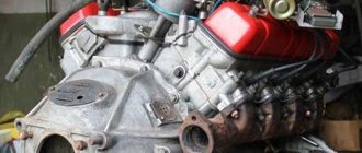
Description and technical specifications
ZMZ 402 series engines are unpretentious in operation and quite easy to maintain. Gasoline engines with a carburetor have 4 cylinders arranged in a row. They were installed mainly on GAZ cars: Volga and Gazelle.
The working volume of the power unit is 2.445 liters, which allows it to develop a power of 100 hp. With. or 73.5 kW. The compression ratio is 8.2 - this allows the use of AI-92 gasoline. The cylinder diameter and piston stroke are 92 mm. The total weight of the unit is 181 kg. The exhaust system includes exhaust gas recirculation, which significantly reduces environmental pollution and allows you to comply with regulations.
Electrical equipment of the GAZ-AA car
Six-volt GAZ-AA equipment, with a “plus to ground” polarity, was typical for that time. Consumers were powered by a 3ST-80 battery with a capacity of 80 Ah, or a GBF-4105 generator with an output of 13A and a power of 80 watts. The same remained true for all GAZ-MM cars.
For comparison, we point out that the GAZ-M1 passenger car, with virtually the same engine, immediately received a GM-71 generator, with an output of 18 A and a power of 100 watts. It would seem that everything is quite clear - the bureaucratic “emka” has as many as four more consumers: a second sound signal, a second, rear right light, interior lamp, and even a “cigarette lighter” (cigarette lighter, in the terminology of those years).
But what fundamentally prevented the lorry from being given a more powerful generator and a battery of larger capacity for more reliable engine starts in cold weather? After all, trucks, as you know, belong to the category of means of production...
But inertia type starters, models MAF-4006, power. 0.9 hp on all pre-war GAZ cars were still the same.
As mentioned above, the 4-cylinder pre-war engines of GAZ cars had three types of ignition distributors, and of course, completely interchangeable when installed on the engines.
On GAZ-AA, the IGTS-4003 unit was used, with a lamella (using contact bars) distribution of high-voltage pulses across the spark plugs. It had only manual remote ignition timing adjustment.
Almost the same externally, the IM-91 device, which received a centrifugal ignition advance machine, was installed on passenger car engines.
And finally, the GAZ-64 and GAZ-67 jeeps received R-15 and R-30 units, not only with automatic ignition advances, but also, unlike the “emoks”, with easily removable distributor caps and plug-in connections that are familiar today, “soft” high-voltage wires.
Let the reader not be surprised or puzzled by the completely unsystematic, independent of reality, alphanumeric designations of components and devices of pre-war automotive electrical equipment.. Perhaps, according to the standards of that time, they encrypted not the first letters of the functional purpose of the products, but the names and surnames of the designers specific products. In any case, we, alas, cannot give an intelligible explanation for such “nonsense”...
But what did semi-trucks have, at least GAZ-MM of post-war assembly? And still the same “Option No. 1” as GAZ-AA in the early 30s... Summarizing all of the above that the “lawns” at the plant were completed according to the “residual principle”, one gets the impression that they are in the production program GAZ were, in fact, rogue cars. Although this, automatically, could be attributed to their drivers. And the priority was “personal equipment” for officials and promising models.
As the reader understands, classic battery ignition systems were used on lorries, although in the 30s there were also ignition systems from magnetos - autonomous high-voltage pulse generators. The domestic industry produced magnetos of the SS-4 and SS-6 types, respectively, for 4- and 6-cylinder engines. But none of the sources of information at our disposal from those years confirms that magnetos were also used on the engines of ordinary flatbed semis.
The head lighting systems of pre-war Gorky trucks were more advanced than those of their peers - Moscow three-ton trucks. Even then they had “low” and “high” beams (ZIS cars have a single mode), and a separate switch only for lighting (Moscow cars have a common switch for all circuits). In the lorry, the low beam had a lamp power of 21 candles (21 watts), and the high beam had a lamp power of 32 candles. At that time, the aforementioned “cargo” generators did not allow more.
Unified with other trucks, the only rear round lamp had two sections. The side light section was covered with the usual red glass, and the stop light section was covered with yellow glass. However, according to the standards of that time, the power of the stop signal lamps was 15 light.
On the electrical diagram, the reader can see a gasoline level indicator. But this indicator was mechanical, connected to a float in the tank, located behind the “dashboard”. Simply, the location of the indicator scale was chosen taking into account the window for it in the general instrument cluster. This combination also included an ammeter and a coil speedometer. The speedometer coil, with speed numbers printed on it, was rotated relative to the stationary mark on the glass of the device.
History of engine development
The 402 engine began to be installed in cars in 1958. At that time it had a different designation - ZMZ-21A and ZMZ-24D, but it was still the same engine. The prototype was an even earlier modification, which the designers worked on in 1954-1955. Then it was a completely new engine option for the GAZ-56 car, which did not even leave the assembly line. The 402nd unit began to be called only in 1980.
The main representatives of the 402 line are:
- ZMZ-402.10 as the main basic option for AI-92 gasoline.
- ZMZ-4021.10, consuming A-76 fuel.
- ZMZ-4022.10, which has a new type of ignition, the so-called pre-chamber-torch.
During the operation of 402.10 engines, they often tried to use cheaper fuel. To do this, the car owners converted the engine to run on gasoline with a lower octane number. As for the flagship of the 402 line - ZMZ-4022.10, there are opinions that the idea of \u200b\u200bprechamber-torch ignition was taken from Honda's Japanese colleagues.
Since 1996, a younger and more modern brother of the 402 appeared - ZMZ-406. For some time, both lines were installed on cars of the Gorky Automobile Plant. Nowadays the 402 engine can only be found in spare parts.
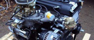
Modification of the Gas 53 engine
Since the GAZ-53 power plant is unpretentious, with an increased resource, craftsmen often use the engine for tuning. Additionally, the work is stimulated by the availability of the price of the device and spare parts. For this reason, owners prefer to install the engine on other cars, such as Gazelle and UAZ.
It seems that the engine is not suitable for such cars in terms of weight and dimensions. But, thanks to the use of aluminum, the motor actually weighs relatively little (230-270 kg). This factor does not negatively affect the chassis; the engine fits in the space under the hood and is compatible with these cars. To adapt to changing conditions, some elements in the design of products are changed: fastenings, cooling, etc.
Improved GAZ-53:
A popular modification is the installation of an injector on the power unit. The procedure requires knowledge and skills, since it is difficult to adjust the engine to the changed parameters. A standard carburetor is not able to make the consumed mixture of improved consistency, so an injector is relevant in this case. By the way, attempts to install the product on the engine were also made by the plant. Thus, in the eighties, modifications of the “504.10” and “5232.10” engines received fuel injection as standard. The injection engine was distinguished by increased power, efficiency, and an increased range of settings. However, these engines did not make it into serial production and most users know nothing about the modifications.
Gas and gasoline: competition for centuries
Surely not everyone knows that the gas engine is older than the gasoline engine. The first internal combustion engine (ICE) running on gas fuel was invented by Belgian engineer Jean Etienne Lenoir in 1860.
The progenitor of modern gas engines literally “devoured” gas, producing an efficiency of only 4%.
Its competitor, running on liquid fuel, was born two decades later. The German designer Gottlieb Daimler created a single-cylinder gasoline engine that surpassed the gas engine in power.
Further development of internal combustion engines took place on the basis of gasoline engines, and until the end of the last century they remained the undisputed leaders. However, the rise in price of gasoline made us think about using a cheaper type of fuel, and the eyes of automakers again turned towards more affordable gas.