As you know, the heart of any mechanism is its engine, so the quality and durability of the machine depends on its choice. And in order to correctly select this integral part of any mechanism, you need to have a good understanding of this issue.
Nowadays there are quite a large number of types of engines. Basically, engine qualification occurs according to the following scheme:
- According to the location of the camshaft.
- According to the location of the valves.
Further, engines are usually divided into a whole series of subtypes. But before this, it is important to understand the second position, because it largely determines how powerful and durable the engine will be. In accordance with the arrangement of valves, engines can be lower-valve, overhead-valve and, accordingly, with a mixed valve arrangement.
How are engines constructed?
Bottom engine. The camshaft is located at the bottom of the cylinder block, and is connected to the crankshaft by two gears. The ratio here is the same as that of the upper cylinders, 1:2, so the camshaft rotates at half the speed of the crankshaft. The camshaft moves the valve lifter rods, which in turn move the valves. Top engine. The camshaft is located on top, in the cylinder head. Driven by chain or belt. The camshaft directly moves the valve lifters. When using two camshafts, each cylinder receives not two, but four valves, which increases the speed of filling and releasing the cylinders, and therefore reduces power losses. The valve lifters are lighter, so they can operate at higher speeds, which also increases engine power.
The shape of the combustion chamber of a lower valve engine and the influence of the compression ratio on its design
Increasing the engine compression ratio makes it possible to slightly increase its power and reduce fuel consumption. However, the literature indicates a limit value of the compression ratio for a low-valve engine of 6.0 units, above which it is not recommended to rise. I tried to figure out what processes determine this.
Figure 1. Theoretical maximum power of the Ford T engine depending on the compression ratio (without taking into account the influence of gas-dynamic losses, which increase at a high compression ratio)
Figure 2. Comparison of power and torque curves for Ford T engines with compression ratios 4.0 (stock) and 6.0
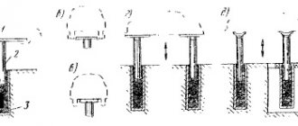
First, about the types of combustion chambers from photographs. The first known design of combustion chambers of the 1914 model is flat, evenly stretched over the surface of the piston and valve plates (Fig. 3). It is characterized by low turbulence and a long flame front path. The spark plug is usually located above the intake valve (?). The second design - the vortex chamber, or Ricardo chamber (Fig. 3) has an increased volume in the valve area (comparison of the cross sections of the chambers in Fig. 4), and is connected to the cylinder with a slightly narrowed gap. Turbulization is achieved by displacing the mixture from the cylinder into the combustion chamber at the end of the compression stroke through a narrowed gap. Ricardo notes that the degree of turbulization can be controlled by changing the degree of narrowing of this gap. The dimensions of the combustion chamber are reduced by bringing the surface of the head closer to the part of the piston farthest from the spark plug (about ½ of the piston area). The spark plug is located approximately in the center of the combustion chamber, slightly closer to the exhaust valve, since the likelihood of detonation occurring above it is greatest. Turbulization of the mixture primarily reduces the influence of overheated areas of the mixture near the hottest parts of the combustion chamber, intensively redistributing the selected heat throughout the entire volume. Shortening the path of the flame front reduces the time the mixture is exposed to high temperature and pressure, reducing the risk that detonation will begin in places remote from the spark plug after the combustion process has begun.
Figure 3. Chamber of the 1914 model (stock, compression ratio 4.0) and vortex (Waukesha-Ricardo, compression ratio 5.0) combustion chambers of the Ford T engine
Rice. 4. Comparison of cross sections of combustion chambers arr. 1914 (dotted line) and vortex (solid line)
Rice. 5. The nature of the mixture movement at the end of the compression stroke. Turbulization. Advertising brochure
Rice. 6. Vortex combustion chamber, model 1918 - 1919
Around 1935, the anti-knock properties of gasoline made it possible to raise the compression ratio to 6.0 units. The requirements for the combustion chamber have changed. Ricardo claims that significantly less turbulence was required for the mixture to burn under new conditions. When using a swirl chamber in an engine with this compression ratio, the rate of pressure rise was excessive, degrading thermal performance (and causing the engine to run harshly). To reduce turbulence, the size of the gap connecting the cylinder to the combustion chamber was increased. With a general decrease in the volume of the combustion chamber, this led first to the abandonment of the hemispherical shape, and then to the transformation of the combustion chamber into a channel connecting the valves to the cylinder in such a way that the resistance to the passage of the mixture in all its parts was minimal. Examples of such heads are the heads of the Harley-Davidson KR and KMZ K750 engines.
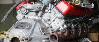
Rice. 7. Section along the cylinder axis of the K750 engine, the outlines of the combustion chamber are visible
Rice. 8. Cylinder heads of the K750 engine
Rice. 9. Harley-Davidson KR cylinder heads
Table. Parameters of various lower valve engines
Ricardo states the following requirements for combustion chamber design for compression ratios greater than 6.0: 1. An intake valve of sufficiently large diameter and with sufficient clearances around its plate to ensure the best possible filling of the cylinder; 2. The shortest path of the flame front (compact combustion chamber, spark plug in its center or slightly offset towards the exhaust valve); 3. Exhaust valve with the smallest possible diameter of the plate, the decrease in capacity can be compensated by increasing its lift; 4. Best cooling of the exhaust valve seat and spark plug; 5. For stable operation on a lean mixture, place the spark plug in a place well blown with a fresh charge; 6. If necessary, use turbulization of the mixture, as in a vortex chamber (?) Further in the book “High-Speed Engines,” Ricardo considers only overhead valve designs.
Rice. 10. Combustion chambers of the GAZ-69 engine. The spark plug is located above the exhaust valve, the lower boundary of the combustion chamber is an arc centered on the spark plug (shortest flame path principle)
Rice. 11. Piston protrusion above the cylinder block connector surface at TDC, engine model unknown
Rice. 12. Design option for connecting the combustion chamber to the cylinder with minimal resistance to gas flow (presumably). Ford V8 engine.
Rice. 13. Tuning kit for Harley-Davidson model K cylinder and head, two spark plugs are visible, the combustion chamber is stretched
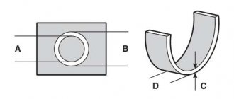
Conclusions. How can you modify the cylinder head and combustion chamber of the K750.
1. Weld the factory hole for the spark plug (there is a rather large funnel there), located in a non-optimal location and poorly ventilated, and make a new one approximately in the middle of the combustion chamber or closer to the exhaust valve; 2. Work with the shape of the displacer, in particular with its edge facing the combustion chamber. At the same time, try not to reduce the cross-section of the gap between the combustion chamber and the cylinder, since the mixture passes there four times - at the inlet, compression, working stroke and during exhaust. Any narrowing will affect four times more than in the intake channel, for example. An example of the transition shape in Fig. 12. In general, the solutions are not obvious; this path requires gas dynamics calculations. 2a. Polish the combustion chamber. 3. Smooth and round the edge of the cylinder protruding into the combustion chamber. 4. It may be useful to increase the displacement due to the cylinder diameter or piston stroke. But for a larger piston stroke, it will be necessary to increase the cross-section of the gap and the throughput of the valves. At least on Harley they went this way - the stroke there is 97/70 = 1.39 times greater than the cylinder diameter. 5. It is hardly advisable to install two spark plugs, since the dimensions of the combustion chamber are small; 6. It is possible to remove the displacer on the cylinder head and select a piston that reaches the mating plane of the head or even protrudes beyond it. Such designs exist (Fig. 11, diagram Fig. 15). This will increase the compression ratio with constant flow sections for the intake and exhaust of gases. It is not yet clear whether it will work or not; I have not found any confirmation of such a scheme based on negative reviews.
7. Take into account the influence of high temperature of the head and cylinder on the anti-knock properties of the fuel mixture and do not require the engine to operate normally on AI92 at a compression ratio of 9-9.5 (Fig. 14).
Rice. 14. Dependence of the required high-grade fuel on the temperature of the engine coolant.
Rice. 15. Increasing the compression ratio due to the protrusion of the piston above the mating plane of the cylinder head. Schematically.
Addition. Topic about modifications to the cylinder heads of the boxer Skunk. When I studied the materials, it seemed to me that with such modifications the transition from the combustion chamber to the cylinder would be too narrow. Now it doesn’t seem that way anymore) Description of modifications to the lower-valve boxer engine on Skunk’s website https://skuns99.blogspot.com/2016/09/750-7503-8253.html
Rice. Photo of modified K750 heads from the Skunk website.
What is confusing is the author’s mention that after modifications the engine began to run noticeably quieter without mufflers. This may indirectly indicate greater resistance at the outlet.
Sources: Most of the materials were taken from the forum; it is not possible to provide all the links. The ideas are all from the site, I just systematized them and tried to explain them. Article A170478, which served as a catalyst for the “824 cc K750 engine.” Result."
Participants whose links and ideas I used (except for the author of the article) MAD DOCTOR ARTEGRO BUFFOG
Book by G. R. Ricardo. “High-speed internal combustion engines”, Moscow 1960
Other sources from the comments to the first article: https://mtfctulsa.com/Tech/head_design.htm https://www.mtfca.com/discus/messages/599638/657061.html?1467781005 https://www.jalopyjournal. com/forum/threads/flathead-combustion-chamber-…
Comparison of engines.
Bottom engines are noticeably simpler and cheaper to manufacture than top engines. The camshaft in such engines is lubricated noticeably better than in overhead engines, because it is located low, slightly above the crankshaft.
The famous sports car Dodge Viper, with an engine capacity of more than eight liters, is also equipped with a lower engine. Many Bugatti cars are also equipped with lower engine engines. A serious plus of the lower engine is the greater reliability of the gas distribution mechanism. There is no belt or chain to break, just two gears. When gears are made with high quality, their resource reaches half a million kilometers, in contrast to a resource of 40-50 thousand for belts or 150 thousand for chains. The use of more than two valves per cylinder is not possible in bottom-propelled engines. The design is too complex and heavy.
The second tangible advantage is that such engines are much simpler in design than overhead engines, therefore they are lighter and easier to repair. However, downstream engines are a dead-end branch of automobile engine evolution. Upper axle engines, unlike lower axle engines, are developing by leaps and bounds. The power in them increases both by increasing the piston stroke and by increasing the maximum speed. Therefore, today low-volume, high-power engines are gaining popularity. For example, Audi managed to make a 1.8-liter engine with a capacity of 480 horsepower. This engine is used in Formula 2 racing.
Overhead engines have greater power density and therefore greater efficiency. They have enormous potential for further development, which is why all serious passenger car manufacturers have switched to overhead engines.
The few advantages of lower-beam engines are inferior to the enormous potential for the development of upper-beam motors. The time of downstream engines is irrevocably passing.
Did you like the article? Subscribe to the channel to stay up to date with the most interesting materials
Source
Timing device
The four-stroke internal combustion engine is the most common power unit used in the modern automotive industry. It got its name from the number of phases required to complete one cycle of work, or rotate the crankshaft by 720 degrees.
The injection phase of fuel or fuel-air mixture, compression of the working fluid by the piston, power stroke and exhaust gas release. In the model of an ideal engine, all phases are spaced apart in time, there is no overlap between them, which, in turn, ensures that the maximum possible operating values of power, torque and engine speed are obtained.
In practice, unfortunately, things are somewhat worse. The design of the gas distribution mechanism, which is responsible for the execution of the fuel injection phase and removal of exhaust gases, its diagram and principle of operation are the main topic of this article.
Comparative analysis of Chinese engines CG, CB, GS, YB.
As many years of practice have shown, motorcycles from China are one of the most sought-after products on the world market. Hundreds of thousands of replica motorcycle models are produced every year. But even such a large supply is not able to fully satisfy the demand of the domestic and foreign markets. Every year Chinese technology becomes more popular in our country. And here consumers are faced with a number of questions related to features that only manufacturers can explain. SV and CG or GS and YB engines
Do-it-yourself timing belt replacement
By removing a worn belt and installing a new one in its place, it is easy to change the relative position of the crankshaft and camshaft. In this case, the engine valve timing will shift, which will lead to operational disturbances, even breakdown. The marks on the gears of the drive mechanism serve to visually control the timing adjustment.
After removing the unusable belt, it is necessary to align the marks of the crankshaft and camshaft gears with the slots in the drive mechanism housing. The purpose of this operation is to set a conditional “zero”, from which the engine will begin to operate. Next, you should carefully install the spare belt, being careful not to displace the marks on the gears.
The next step is to inspect and adjust the tension roller force. The purpose of this unit is to hold the belt on the gears of the drive mechanism. You can check that the roller is adjusted correctly by turning the tensioned belt with your fingers. If you can turn it ninety degrees, the tension mechanism is well adjusted. If the belt turns at an angle less than 90 degrees, then it will be tightened; if it is turned at an angle greater than 90 degrees, then it will not be tightened.
When installing, it is very important not to handle the timing belt with oily hands.
This can lead to slippage on the drive gears. A belt purchased at a roadside gas station should be carefully inspected. If storage conditions are violated, even a new timing belt will crack and cannot be used for its intended purpose.
motorcycles
#1326 Tap
- Captain
- 14,484 messages
- From: Moscow
- Vessel:
tap - Name:
busya
OK! Then so. Why is the lower one more vibrated? Maybe the bars are to blame for everything?
What does vibration-loaded mean? I don’t know such a concept.
A good Pobedovsky or Volgovsky engine is not subject to any special vibrations.
#1327 Daddy
- From: Mozhaisk
A good Pobedovsky or Volgovsky engine is not subject to any special vibrations.
any motorcycle engine without a balancer is vibration-loaded
#1328 Andr
- From: Sveti Vlas
- Vessel:
Wind boat - Name:
st.Olga
Please don't start. To each his own. And it wouldn’t hurt to apologize to your interlocutors for “jerking.”
#1329 Tap
- From: Moscow
- Vessel:
tap - Name:
busya
any motorcycle engine without a balancer is vibration-loaded
The balancer is a counterweight on the horse. shaft? So, in general, all engines have it. There are also additional balancing shafts, but quite rarely.
Cost of a new camshaft
Depending on the type and brand of engine, new camshafts cost differently. Prices range from 15,000 to 30,000 rubles. Naturally, this is the average cost of original camshafts for foreign-made cars in the mid-price category.
But the cost of a camshaft is only half the story when it malfunctions. After all, it has yet to be replaced. Here the price range really has no boundaries. Everything, of course, depends on the make, model, year of manufacture of the car and the place where the work will be carried out. You understand that for the officials, replacing the camshaft will cost a lot of money. In a private garage, this work can cost 5 times less. But in this case there are risks in the quality of the services provided.
So if your car needs a camshaft replacement, you must be careful where you choose to repair it since it involves your car's engine, which can be seriously damaged if the camshaft is replaced incorrectly.
Also, do not forget that in many cars it is very difficult to get to the camshaft due to the design features of the vehicle. That is why in such cars the cost of replacing the camshaft cannot be low, since it takes too much time. And if you are the owner of such a car and they announce an inexpensive price tag for a replacement, then you should think about whether such a service will provide a truly high-quality service.
Maybe it's not worth the risk? After all, in the end, your savings may backfire on you. Agree, we are not rich enough to save. You know, a stingy person usually pays twice. Especially when it comes to a complex device like a car.
Main malfunctions and their causes
Like any part in the engine, the camshaft can fail. However, breakdowns are usually caused not by natural wear (an oil film on the friction surfaces should protect against it), but by other reasons:
- Wear of cams, journals or bearings is a direct result of oil starvation or low-quality oil. A problem can also be a non-replaceable oil filter that is clogged to death, and now all the carbon deposits circulate in the engine, clogging the thin channels of the lubrication system;
- Axial runout, which leads to deformation and fracture of the camshaft. The cause is often desynchronization with the fuel supply system.
Since the camshaft is located inside the engine (an engine can have one or two camshafts, and up to four on powerful V-shaped engines), its operation can only be influenced indirectly. This is primarily timely maintenance with the replacement of engine oil and oil filter.
This simple procedure will protect all engine parts from premature wear. Replacing a camshaft is usually not cheap: the part itself is expensive due to high-quality metal and precise processing, plus the work of craftsmen requires time and money. It is better to monitor the condition of the engine and service it on time.
Purpose of the gas distribution mechanism
In simple words, the timing belt is necessary to supply the finished fuel mixture to the engine, as well as to release burnt fuel into the cavities of the cylinders. This function is enabled by valves that open/close at specific times. Most internal combustion engines use a 4-stroke principle, which ensures the conversion of thermal energy into mechanical energy.
The entire process takes place in a cylinder group, where valves and pistons move synchronously in a certain sequence in compliance with the phases. In this case, the timing functions include moving the valves in interaction with the crankshaft. Depending on the situation, the intake/exhaust valves open/close.
Conventionally, the purpose of the timing belt is to ensure the operation of the following four phases:
The engine gas distribution mechanism guarantees accurate and timely opening of the intake/exhaust valve units. In this case, the timing interacts with the crankshaft, and rotation is transmitted to the camshaft using a chain, belt or gears. We will dwell on this issue further below.
Principle of operation
The operation of the gas distribution mechanism is difficult to consider separately, in isolation from the engine operating cycle. After all, its main task is to open and close the valves in time for a certain period of time. Accordingly, on the intake stroke, the intake valves open, and on the exhaust stroke, the exhaust valves open. That is, in fact, the mechanism must implement the calculated valve timing.
Technically it happens like this:
It is also worth noting that during a full operating cycle, the camshaft makes 2 revolutions, alternately opening the valves in each cylinder, depending on the order of their operation. That is, for example, with a 1-3-4-2 operating scheme, at the same moment in time, the intake valves will be open in the first cylinder, and the exhaust valves in the fourth. In the second and third the valves will be closed.
What is a camshaft sensor?
To monitor the timing system, a position sensor is provided on the camshaft, which determines the angle of its rotation. This information (as well as from the crankshaft sensor) is sent to the electronic control unit (ECU), where the fuel supply to the injectors and ignition timing are adjusted.
The sensor operates based on the Hall principle: data comes from a magnetic sensor that reads every revolution of the contact element. In this way, the camshaft rotation speed is read, and based on this data, the operating mode of the injection system is calculated.
A malfunction or error in the sensor leads to blocking of the gasoline engine and difficulty starting the diesel engine.