The compressor is a universal unit that has found quite wide application both in large production and in small workshops. It is also installed on various cars and special equipment. That is why the question of how to create a compressor with your own hands from a Zilov compressor is of great interest to many craftsmen who want to save on purchasing this device.
Household use
To begin with, it should be said that such products will not be very productive, and their production may require high costs. However, there are a lot of application options that make you look for material on how to make a compressor with your own hands from a Zilov compressor.
- First of all, such a device is perfect for inflating car tires.
- Also, such a unit can be used to work with some low-power pneumatic tools.
- Most often, these products are used in workshops for applying paint to surfaces. The fact is that if there is a volumetric receiver, they can work for quite a long time and create the pressure necessary for this.
- Some specialists use such units in blacksmithing and other industries. The main thing is that the technical characteristics correspond to the specified parameters.
Malfunctions
During operation, it is necessary to monitor the technical condition of the mechanism, lubrication and the flow of coolant. It is recommended to use only the oil that is specified in the power plant data sheet. Lubrication with contaminated oil is prohibited.
The compressor does not require daily or special technical inspections, but the drive and fastening reliability are checked periodically once every 8-10 thousand km.
During operation, breakdowns of unit parts may occur; they are repaired immediately. Those that are faulty must be replaced.
The main malfunctions of a truck compressor are divided into 2 types:
- piston group;
- electrical equipment.
The most common defects are:
- Wear of the piston group and violation of valve tightness. Duration of filling the pneumatic system at a crankshaft rotation speed of 2200 rpm. exceeds the time established by the technical specifications (8 minutes). The compressor does not pump up a pressure of 7-7.5 kgf/cm². Piston wear causes oil mist to be drawn from the compressor crankcase into the cylinders.
- The system supercharger does not start. Associated with a lack of voltage in the network, a leaking check valve and improper starting.
- The compressor pumps poorly and does not gain speed. One of the reasons is clogged filters.
- Knocks in the cylinder-piston mechanism. Associated with breakdowns in the discharge part as a result of friction and wear of metal parts.
- The engine hums and does not rotate. This problem is possible due to the operation of the mains power fuse, overload protection, or poor contact.
- Strong heating of the cylinder. Airflow to the cylinder and crankcase is blocked.
- Performance decreases - the suction air filter is clogged.
- Increased vibration.
How to remove and disassemble
In order to replace failed elements, it is necessary to remove and disassemble the compressor:
- Raise the cab, the unit is located underneath it.
- Unscrew the fastening nuts, remove the head together with the discharge valves, gasket, and springs of the inlet elements.
- Unscrew the 3 tubes using the appropriate wrench.
- Unscrew the drive gears and lift the unit towards the front of the vehicle.
Automobile compressor
Novice craftsmen often ask the question of why this particular part is worth purchasing in order to create a compressor with your own hands. They consider the Zil 130 to be a morally obsolete car, and the units that are installed on it are worn out. However, it is immediately worth noting that in our country this particular part is the easiest to find, and its cost directly depends on the condition. At the same time, the simplicity of manufacturing this unit allows for basic repairs and greatly simplifies maintenance.
Also, making a compressor with your own hands from a Zilov compressor is much easier than using other products of a similar type for this. To perform basic tasks, it will practically not even need to be redone. However, if long-term use or heavy loads are required, some modifications will need to be made.
How much does a compressor and its repair cost?
You can buy a compressor for a truck within 7-10 thousand rubles. The cost of repair work in specialized workshops depends on the condition of the unit and the type of fault and is negotiated individually.
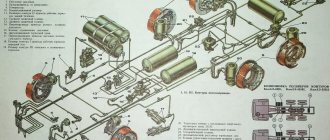
KamAZ vehicles are equipped with a two-cylinder piston compressor 5320-3509015-10 with air cooling. During operation, the compressor takes in air through the engine air filter. The piston (item 8 in the figure), made of cast iron, has one oil scraper ring and two compression rings. The connecting rod bearing is equipped with bimetallic liners. The connecting rod head has a bronze bushing for the piston pin. The head (item 9) of the compressor is made with sockets in which the discharge valves are mounted.
Necessary equipment
To create a compressor with your own hands from a Zilov compressor, you need to solve the issue of transmitting torque to the unit itself. You will also need an engine of a certain power and with a specific number of revolutions. Therefore, some purchases will be required.
Special attention should be paid to the receiver. It is selected in accordance with the tasks assigned to the product. At the same time, a pressure gauge and a safety valve are installed on it, which will be responsible for the required pressure.
Torque transmission
When making a compressor with your own hands from a Zilov compressor, you need to make a very important decision about how the power will be transferred from the engine to the unit itself. At the same time, some masters prefer to connect directly, believing that this way they will not lose the number of revolutions and power. However, it is worth remembering that for such methods of implementing connections you need to have a fairly powerful engine. Therefore, a belt drive is most often used.
When making a compressor with your own hands, they usually try to connect the Zilov compressor to the engine through a gearbox. This way you can get quite a good force during the initial start-up or if there is pressure in the receiver. However, the cost of a good gearbox is quite high, and the option with a belt drive can be considered the most optimal.
Receiver
They usually try to make a typical iron-based compressor from the ZIL 130 compact and mobile. Therefore, using large and voluminous receivers simply does not make sense. Also, you should not purchase these elements of the unit separately, since you can always create them yourself. You can use almost any metal container for this. In this case, it is best to use gas cylinders or old fire extinguishers.
It should be noted right away that further refinement of the receiver will be required. You will need to install a pressure gauge and pressure regulator on it. Usually a separate unit with a gearbox is purchased, which is installed at the entrance to the container. It is also very important to install a back pressure valve. It is adjusted to the optimal operating mode of the future product with a certain margin of 10-15%.
Compressor modification
Even if you plan to make an ordinary garage compressor from a ZIL compressor, the unit itself will need to be slightly modified.
- First of all, it is worth creating cooling. The fact is that such units overheat greatly during their operation and, as a result, not only productivity, but also service life decreases. Therefore, the connecting rods should be drilled, and an oblique tube should be installed in the bottom cover.
- To control the oil level, it is necessary to install a transparent filter at the crankcase outlet. It also makes sense to install a moisture separator, which you can make yourself from a small fire extinguisher.
- The oil tank is also installed separately. It is immediately worth noting that it will be used as an expansion tank and will help normalize the pressure in the system.
Today, there is simply a huge number of various improvements that are aimed at increasing productivity and service life. All of them usually relate to the lubrication and torque transmission system. However, the final choice always depends directly on the purpose of the final product.
Compressor station UST 5453 Kamaz 43118
Compressor station
—
a mobile complex
for carrying out insulation work on gas and oil pipelines.
Caravan finishing and layout
Van body
It is a frame welded structure, the outer cladding is steel sheet, polystyrene foam is used as insulation.
Depending on the purpose and climatic operating conditions, the thickness of the wall panels can be from 30 to 80 mm. The interior of the van body
is made of industrial plastic.
The lower part of the walls of the mobile compressor station
is covered with galvanized steel sheet, the floor is covered with corrugated rubber.
This finishing option is more practical for renovation work. The windows are double-glazed with safety glass. To increase heat and sound insulation, door and hatch openings are edged with double sealing. The van body
consists
of two compartments
:
generator
and
hardware
. Each compartment has ventilation and technological hatches for connecting equipment and making work easier.
Electrical equipment and electrical network
Compressor station
equipped with equipment for hot spraying of two-component thermoactive materials, quality control equipment, a generator set as a source of electricity, and a compressor unit to provide compressed air for work.
The equipment
is designed
to carry out work on preparing the surface and applying insulating coatings to oil pipelines.
The compressor station is equipped with the required number of lamps: usually dust- and moisture-proof fluorescent lamps are used, with a degree of protection IP 54, IP 65, as well as interior lamps with a switch on the housing. The wiring is carried out with a copper cable of the rated cross-section openly in PVC boxes, which are combined into a separate electrical panel and grounded. Electricity distribution is controlled using an electrical panel installed inside the cabin. Distribution boards are equipped with a residual current device.
Lifting equipment
The cantilever jib is mounted next to the rear entrance door of the van body
and is designed for loading and unloading equipment materials. The load capacity is 250 kg on a folding beam and 500 kg on a rigidly fixed console, the rotation angle is 200 degrees.
Retractable gangway and removable ladder
Also one of the features of the Kamaz 43118 compressor station
are a retractable ladder, through which personnel enter and move goods inside
the van
, and a removable ladder, which provides access to the compartment with the generator set.
For convenience and space saving, the ladder, like the ladder, is retracted into a niche under the floor of the van in the transport position. The design of the stairs and ramp provides wide steps, which make it easier to descend and ascend into the van
.
Assembly
First, you should make a frame on which the compressor will be installed with your own hands. ZIL 130 has certain seats for this unit, which must be transferred to the frame. This way you won’t have to make additional holes in the compressor itself, and you can use an additional shock absorption system.
Next, the engine is mounted on the frame. In this case, the fixation is carried out in a rigid position, at a distance necessary for the transmission of torque. The receiver and other elements that can be connected via hoses can be placed separately. Sometimes it’s easier to connect them at the place of work, so as not to weigh down the frame itself.
Recommendations from experts
- If a compressor is made from Zilovsky, the tools will need to be selected very carefully. You will need to have a drill, a welding machine, a set of wrenches and much more. Situations may also arise when some types of work are easier to do in the factory or using special machines.
- To create shock absorbers when fixing all units to a frame or supporting frame, it is best to use rubber gaskets or inserts. However, it is worth remembering that with intensive use they wear out quickly and you should always have spare ones.
- When purchasing a compressor, you must be very careful, since the appearance of the product does not indicate the condition of its internal components and assemblies. It is simply not possible to check the product on the spot, which means that such a purchase should only be made from trusted sellers.
- If the problem with overheating of the compressor is not solved, then it must be operated in a gentle mode. This way it will last much longer, although this may cause some inconvenience during operation. That is why the unit is selected for specific needs.
- You can install a pressure gauge with special contacts on the product, which are connected to the electrical engine starting circuit. This automates the operation of the device and will also reduce the likelihood of rapid overheating.
- The electrical circuit for connecting the compressor to the electrical circuit directly depends on the type of engine selected. At the same time, you should not come up with workarounds for starting the primary winding so as not to lose power. This will affect the operation of the product if there is residual pressure in the receiver, even with a check valve and a fairly powerful engine.
Design and principle of operation
KamAZ trucks are equipped with single- and two-cylinder piston-type units, and rarely with membrane-type units.
The compressor device is presented as follows:
- Connecting rod.
- Piston.
- Cylinder with spacer.
- Rings:
- sealing;
- oil scraper;
- compression
- Sliding bearings.
- Carter.
- Crankshaft,
- Drive gear.
The single-stage compression mechanism is located on the front of the engine flywheel housing. The piston is made of aluminum and has a floating pin secured by thrust rings. Atmospheric air enters the cylinder from the intake manifold of the power plant, which is forced out into the pneumatic system through the discharge valve in the cylinder head.
Conclusion
When assembling a compressor from Zilovsky with your own hands, you should remember that this work will require the performer to be able to handle various tools and adhere to the technique of processing all kinds of parts. It is also worth remembering that the purchase of certain units will lead to costs, which means that before starting work, you should carefully evaluate all the costs and compare them with your capabilities. The fact is that with intensive use, such a compressor only lasts for a couple of years.
Homemade cars, tractors, all-terrain vehicles and ATVs
A compressor made from a compressor from ZIL: photo and description of a homemade product.
Hi all! So I decided to make myself a compressor for my home workshop. Spare parts were already available: a ZIL-130 compressor, an 80-liter automobile gas cylinder), an electric motor, a magnetic starter, wheels, an emergency pressure valve from ZIL, etc.
Additionally, I bought a pressure switch (in the end it’s a water switch, but initially I bought a compressor with a button (it’s more expensive), and a reducer unit for air distribution, as well as fittings, wires, and a plug.
The manufacturing process is shown in the photo.
I made a receiver from a cylinder.
The pressure was set to turn off at 7 atm and turn on at 4 atm.
The compressor was slightly modified, the connecting rods and bearings were drilled on three sides. The compressor itself was installed through a gasket on a steel base, and that tube with a cap, the one that comes off from the bottom side, was originally planned for monitoring and filling oil, but in the process we also had to make a tank (breather). My opinion is that if it weren’t for most of the spare parts that I already had in stock, then I don’t think it’s worth bothering with at all, you can buy a ready-made one.
We also recommend reading an article on the topic - how to make a compressor from a refrigerator.
You can effectively and quickly clean any part or structure surface for further repair or use using sandblasting. But this device requires a source of compressed air with the necessary pressure and performance. A self-made compressor for sandblasting will save you from purchasing expensive and not always sufficiently reliable equipment.
Compressor disassembly
Disassembling a compressor mounted on a stand begins with removing the cylinder head. Then the intake valves, their guides and seats are removed from the cylinder block sockets.
Holding the block head in a vice, unscrew the discharge valve plugs, remove the valves, seats and sealing gaskets.
By bending the tendril of the lock washer 2 and unscrewing the nut 3 securing the crankshaft drive gear, remove the lock washer.
Then, using the device, the compressor drive gear is removed and key 6 is removed from the groove of the crankshaft.
In order to remove the mechanical seal and spring from the crankshaft, you must first remove the thrust ring from the crankshaft.
Having turned the compressor on the stand with the bottom cover up, unscrew the fastening bolts and remove the bottom cover with gasket 24.
Then you need to unscrew and unscrew the nut securing the connecting rod covers and remove the covers.
By tapping the end of the lower head of the connecting rod with the handle of a hammer, remove the piston and connecting rod.
After removing the liners, you need to connect the covers and connecting rods in pairs with bolts so as not to confuse them in the future. The connecting rod and cover are processed as an assembly, so they are replaced only in pairs.
Turning the compressor with the cylinder block up, unscrew the nuts securing the block to the crankcase and remove the cylinder block with the 21 oil deflector plates.
After this, unscrew the bolts securing the rear crankcase cover 23 and remove the cover.
Before pressing the crankshaft out of the crankcase, the thrust ring of the main bearing installed on the drive gear side is removed.
Holding the connecting rod in a vice, remove the compression oil rings from the piston and remove the thrust ring of the piston pin.
After pressing out the piston pin 14, disconnect the piston from the connecting rod, and then press out the bushing from the upper head of the connecting rod.
A practical option
The design based on the compressor from MAZ, ZIL 130 - 157 has proven itself as a reliable, efficient device. The unit from these cars will require minimal do-it-yourself modifications. From MTZ, GAZ is ineffective, but from KamAZ it needs major improvements. The receiver is installed based on the needs for sandblasting - a 50 liter gas cylinder or a ready-made one from a KamAZ vehicle and a smaller one from a ZIL, which already have the necessary holes.
The approximate layout of a self-made device and the pneumatic connection diagram for the compressor are as follows. The receiver, in a horizontal position, is installed on supports with wheels. A compressor without a bottom cover is installed on a piece of channel 200–250 mm wide through a paronite gasket. At the opposite end of the channel, through milled grooves, an electric motor is mounted on feet. The grooves are necessary for tensioning the belt, which is selected with a small cross-section so that power losses on the drive are minimal. The channel is attached to the top of the receiver, the wiring from the compressor to the receiver is connected from above and from the end, a pressure control gauge is installed, an overload valve and an outlet fitting with a valve are mounted from the end.
Engine KAMAZ 740.10-210
Engine
KAMAZ vehicles are equipped with engines of the KAMAZ-740.10 models;
KAMAZ-7403.10 or KAMAZ-740.11-240. Features of the design, maintenance and repair of KAMAZ-740.11-240 engines are set out in the operating manual 740.11-3902006RE.
KAMAZ-740.10 and KAMAZ-7403.10 engines have the following design features:
- pistons cast from high-silicon aluminum alloy, with a cast-iron reinforcing insert under the upper compression ring and a colloidal-graphite running-in coating for the skirt;
- cylinder liners, volume-hardened and flat-top honed;
- piston rings with chrome and molybdenum coating of the side surfaces;
- three-layer thin-walled steel-bronze liners for main and connecting rod bearings;
- a closed cooling system filled with low-freezing coolant, with automatic temperature control, a fluid coupling for the fan drive and thermostats;
- highly efficient filtration of oil, fuel and air using paper filter elements;
- electric torch air heating device, ensuring reliable engine starting at negative ambient temperatures down to minus 25°C.
Cylinder block and drive units
The cylinder block is cast from alloy gray cast iron integral with the upper part of the crankcase. The crankcase part of the block is connected to the main bearing covers with transverse tie bolts, which gives strength to the structure. To increase longitudinal rigidity, the outer walls of the block are made curved. The bosses of the cylinder head bolts are bosses on the transverse walls that form the water jacket of the block.
Technical specifications
Intake valve timing:
- opening (up to w.m.t.) - 13°
- closing (after vmt) - 49°
Same exhaust valve:
- opening (up to E.M.T.) - 66°
- closing (after v.m.t.) - 10°
Oil pressure in a warm engine, kPa (kgf/cm2):
- at rated speed - 400.2-550.4 (4.0...5.5)
- at minimum idle speed, not less than - 98.1 (1.0)
Nozzles (closed type) mod. 33 mod. 271
Pressure of the beginning of lifting of the nozzle needle, MPa (kgf/cm 2):
- used... 20 (200) <21.5 (215)
- new (factory 22.0...22.7 23.5...24.2 adjustments) - (220...227) (235...242)
The supercharging system is a gas turbine with two turbochargers.
The left row of cylinders is shifted forward relative to the right by 29.5 mm, which is caused by the installation of two connecting rods on one crank pin of the crankshaft.
A cover is attached to the front of the block that covers the hydraulic coupling of the fan drive, and at the back there is a flywheel housing, which serves as a cover for the accessory drive mechanism located at the rear end of the block.
Wet-type cylinder liners are easily removable, made of special cast iron, volumetrically hardened to increase wear resistance.
The liner mirror is processed by flat-top honing to obtain a grid of depressions and areas at an angle to the liner axis. This treatment helps retain oil in the depressions and improve the running-in of the liner.
In the connection between the liner and the cylinder block, the water cavity is sealed with rubber O-rings. In the upper part there is a ring installed under the collar in the bore of the liner, in the lower part two rings are installed in the bores of the block.
The units are driven by a gear with spur gears, the gas distribution mechanism is driven from the drive gear mounted with interference on the crankshaft shank, through a block of intermediate gears. The idler gear unit rotates on a double tapered roller bearing. The camshaft gear is mounted on the shaft shank with interference fit. When assembling, you must ensure that the marks on the end of the gears in mesh are aligned.
The high pressure fuel pump is driven by a gear meshed with the camshaft gear. Rotation to the high-pressure fuel pump is transmitted through the driving and driven coupling halves with elastic plates that compensate for misalignment.
The compressor drive gear and the power steering pump drive gear are engaged with the fuel pump drive gear.
Tightening torques for the idler gear axis mounting bolts are 49.1…60.8 N. m (5...6.2 kgf.m), roller bearing mounting bolt 88.3...98.1 Nm (9...10 kgf.m).
The circumferential clearance in the drive gears of the units is 0.1...0.3 mm.
crank mechanism
The crankshaft is made of steel, made by hot stamping, hardened by nitriding or hardening of the connecting rod and main journals by high-frequency currents.
The crankshaft has five main bearings and four connecting rod journals. The connecting rod journals of the shaft have internal cavities closed with plugs, where the oil is subjected to additional centrifugal cleaning. The cavities of the connecting rod journals communicate through inclined holes with transverse channels in the main journals.
An oil pump drive gear and a drive gear assembled with an oil deflector are installed on the toe and shank of the crankshaft. The external counterweights are removable and secured to the shaft with a press fit.
The axial movements of the crankshaft are limited by four steel-aluminum half-rings installed in the grooves of the rear main bearing so that the side with the grooves is adjacent to the thrust ends of the shaft, and the lug fits into the groove on the rear main bearing cover.
The crankshaft shank is sealed with a rubber self-clamping oil seal installed in the flywheel housing.
The flywheel is made of gray special cast iron, bolted to the rear end of the crankshaft and secured with two pins and a mounting sleeve. The ring gear is mounted on the flywheel using a hot-press fit and serves to start the engine with a starter. The number of teeth on the flywheel ring is 113.
On the outer surface of the flywheel there is a groove for the flywheel lock, which is used when regulating the engine.
Steel connecting rods, I-section; The bottom head is made with a straight and flat connector. The connecting rod is finally processed as an assembly with a cap, so the connecting rod caps are not interchangeable. On the cover and connecting rod there are pairing marks in the form of three-digit serial numbers. When assembling, the marks on the connecting rod and the cover should be on the same side. In addition, the cylinder serial number is stamped on the connecting rod cover. There are two connecting rods installed on each crankpin of the crankshaft. The sliding bearings are a sleeve made of a bimetallic strip in the upper head of the connecting rod and removable interchangeable liners in the lower one. The connecting rod cover is secured with two connecting rod bolts and nuts.
Pistons are made of high-silicon aluminum alloy with an insert (special cast iron) for the upper compression ring and a colloidal-graphite coating of the skirt. The piston is equipped with two compression rings L2 and one oil scraper ring L1. Compression rings have a one-sided trapezoidal cross-section and are made of cast iron of a special chemical composition. The working surface of the upper compression ring is covered with chromium, the lower - with molybdenum.
| Selection of the piston according to the distance from the crankshaft connecting rod journal in its upper position to the cylinder liner sealing collar | ||
| Piston version index | L | L1 |
| 10 | 260,12… 260,24 | 75,67… 75,71 |
| 20 | 260,24… 260,35 | 75,78… 75,82 |
| 30 | 260,35… 260,46 | 75,89… 75,93 |
| 40 | 260,46… 260,57 | 76,00… 76,04 |
Rectangular oil scraper ring with twisted spring expander and chrome-plated working surface.
The combustion chamber is located in the piston head. By selecting a piston design to reduce the clearance above the piston, when assembling the engine, the protrusion of the piston above the sealing end of the liner is ensured within 0.5...0.7 mm. The piston variant index is marked on its bottom: 10; 20; thirty; 40, as well as at the non-working end of the sleeve protrusion. Spare parts are supplied with pistons with the index “10”, which during repairs can be installed in sleeves with any index.
The piston and connecting rod are connected by a floating pin; the axial movement of the pin in the piston is limited by retaining rings. The piston pin is made of chromium-nickel steel in the form of a hollow cylindrical rod, strengthened by carburization and hardening.
The bearing shells for the crankshaft and the lower head of the connecting rod are replaceable, thin-walled, three-layer, with a working layer of lead bronze. The upper and lower crankshaft main bearing shells are not interchangeable. The upper liner has a hole for oil supply and a groove for its distribution.
Gas distribution mechanism
The gas distribution mechanism is designed to admit air into the cylinders and exhaust exhaust gases. The opening and closing of the intake and exhaust valves occurs in strictly defined positions with respect to the top and bottom dead centers, which correspond to the rotation angles of the crankshaft journal indicated in the valve timing diagram.
The engine gas distribution mechanism is overhead valve. The camshaft cams activate the tappets in a specific sequence. The rods impart rocking movements to the rocker arms, which, overcoming the resistance of the springs, open the valves. The valves close under the force of compressed springs.
Torque is transmitted to the camshaft from the crankshaft through the drive gears of the units.
The cylinder heads, cast from aluminum alloy, have cavities for coolant that communicate with the block jacket. The joints of the cylinder head and liner, head and block are sealed with gaskets. A gas joint ring is pressed into the groove on the mating plane of the head, with which the head is directly installed on the cylinder liner collar. The tightness of the seal is ensured by high precision processing of the mating surfaces of the ring and cylinder liner and, additionally, by applying a lead coating to the surface of the ring to compensate for micro-roughness of the sealing surfaces. The coolant bypass channels are sealed with silicone rubber O-rings installed with shanks in the holes of the cylinder head. The head space, engine oil drain hole and rod passage are sealed with a molded cylinder head gasket.
The inlet and outlet ports are located on opposite sides of the head. The inlet channel has a tangential profile for swirling air in the cylinder.
Cast iron seats and metal-ceramic valve guides are pressed into the head, which are bored after pressing. Each head is secured to the block with four bolts. The valve mechanism is closed by an aluminum cover, under which there is a sealing gasket.
The camshaft is steel, the surfaces of the cams and bearing journals are cemented and hardened by high-frequency currents. The shaft is installed in the camber of the block on five plain bearings.
The rear support bearing is a bushing clad with bronze and pressed into a removable cast iron housing. Bushings made of bimetallic tape, pressed into the transverse partitions of the block, serve as bearings for the remaining shaft supports.
The axial movement of the camshaft is limited by the bearing housing, against the ends of which the gear hub rests on one side and the thrust collar of the rear shaft journal support on the other. The rear support bearing housing is secured to the block with three bolts.
The pushers are of the mushroom type, hollow, with a cylindrical guide part, made by cold heading of steel with subsequent surfacing of the plate with bleached cast iron. The inner cylindrical part of the pusher ends with a spherical socket for resting the lower end of the rod.
The inlet and outlet valves are made of heat-resistant steel. The diameter of the exhaust valve head is smaller than the diameter of the intake valve head. The stems of both valves at a length of 125 mm from the end are coated with graphite to improve running-in.
While the engine is running, the valve stems are lubricated by oil flowing from the rocker arm interfaces with the axles and sprayed by the valve springs. To prevent oil from entering the cylinder along the gap between the valve stem and the guide sleeve, a rubber cuff is installed on the intake valve sleeve.
The pusher guides, cast from gray cast iron, are removable to increase the repairability and manufacturability of the unit. There are four guides installed on the engine, in which four pushers move. Each guide is mounted on two pins and attached to the cylinder block with two bolts. The bolts are secured with flange washers.
The push rods are steel, tubular, with pressed and crimped tips. The lower tip has a convex spherical surface, the upper one is made in the form of a spherical cup for the stop of the rocker arm adjusting screw.
The valve rocker arm is forged steel, with a bronze bushing, and is a double-arm lever with a gear ratio of 1.55. An adjusting screw with a lock nut is screwed into the short arm of the rocker to adjust the clearance in the valve mechanism. The rocker arms of the intake and exhaust valves are installed in cantilevers on axles made integral with the rocker arm stand; The stand is mounted on a pin and secured to the head with two studs. The axial movement of the rocker arms is limited by a spring clamp. Lubricant is supplied to each rocker arm through holes in the rocker arm post.
Valve springs are cylindrical with a uniform coil pitch and different winding directions. Each valve has two springs. The lower ends of the spring rest on the head through a steel washer, and the upper ends rest on the plate. The plates rest against a bushing, which is connected to the valve stem by two conical nuts. The detachable connection between the sleeve and the plate allows the valves to rotate relative to the seat.
Modification of the compressor of the ZIL 130 pneumatic brake drive
In the housing, in a convenient place, 10 mm below the center of the crankshaft, a hole is drilled for filling oil. A thread is cut for the cork. A threaded hole is made at the bottom of the channel for a plug to drain the oil. On the side opposite the pulley, a fitting with an oil-resistant hose or tube is screwed into the bearing cover, which is connected to a container that serves as an expansion tank for lubricant and breather. You can use a clutch reservoir for brake fluid from a VAZ. It is located opposite the cylinder head of the unit. To install the fitting, the car's intake valve is unscrewed.
They change the crankshaft lubrication system: drill 2 countersunk holes in each connecting rod with liners assembly at the point of transition from the rod to the lower head of the connecting rod. Drill one at a time into the connecting rod caps. The holes have a D of 3mm, a countersink of 10mm, the drilling direction is towards the center of the shaft. You will need to disassemble the compressor - remove the head, unscrew the connecting rods. The resulting holes will provide the liners with lubrication due to splashing. The cylinders are lubricated during operation by the resulting oil mist.
The unloading device of the unit (soldier) remains factory - it will allow you to regulate the pressure at which the unit will turn off. The discharge tube must be connected to the supply receiver (if there are several of them). It is also recommended to use a car pressure gauge and overload valve.
To turn off the engine when the compressor is idling with your own hands, you can provide automatic on/off. Between the unloading channel and the pressure regulator of the automobile unit, you will need to insert a threshold pressure sensor - a VK12B brake light switch from UAZ, GAZ, and so on. Its catalog number is 40P-37210010. The control circuit will become simpler if a pressure sensor is found whose contacts open when pressure is applied. In order for a self-assembled compressor to operate more smoothly, a balanced flywheel should be installed on the pulley of the automobile unit.
For normal operation, a cooling system is not required - when operating at constant speeds, the unit rarely heats up to more than 60°C. On a car, its operating temperature is 90°C, but 120°C is not critical. In case of intense operation, an evaporative cooling system can be made. A 4-5 liter container is installed above the level of the head, the hoses are connected to the compressor with the coolant inlet/outlet. This will allow you to maintain the temperature no higher than 100°C.
KAMAZ vehicle compressor repair
Content:
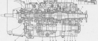
KAMAZ compressor design
1 - crankcase;
2 — drive gear; 3 - seal; 4 — seal spring; 5 - key; 6, 18 — bearings; 7— crankshaft; & — connecting rod; 9 - piston; 10 — piston pin; 11 — cylinder head; 12 — cylinder head gasket; 13 — cylinder block; 14 — coolant supply elbow; 15—reflective plate; 16 — gasket; 17 — rear crankcase cover; 19 — lower crankcase cover; 20 - valve body; 21 — connecting rod cover fastening bolt; 22 - nut; 23 — connecting rod liner; 24 — cover of the lower head of the connecting rod; 25 - pin The single-stage compression mechanism is located on the front of the engine flywheel housing. The piston is made of aluminum and has a floating pin secured by thrust rings. Atmospheric air enters the cylinder from the intake manifold of the power plant, which is forced out into the pneumatic system through the discharge valve in the cylinder head.
The liquid is supplied from the engine cooling system and reduces the heating of the cylinder head. Oil flows through the pipelines to the rubbing parts, which lubricates the rear end of the compressor crankshaft and the connecting rod-piston group by splashing.
As soon as the pressure of the pneumatic system reaches 0.8-2 MPa, the pressure regulator is activated and stops the air supply. When the indicator drops to 50 kPa, it closes the outlet, and the compressor pumps air into the system again.
The design and principle of operation are similar to autocompressors for passenger cars, with the only difference being that KamAZ trucks have double protection against short circuits and overheating.
Common malfunctions of the KAMAZ compressor
Rattling and knocking in the cylinder and piston group
A malfunction of the piston group is one of the common causes of compressor failure. To recognize a defect, simply listen to the sounds the compressor makes during operation. If work is accompanied by knocking, rattling, grinding and other metallic sounds. This means that its discharge part is faulty. There are a lot of moving metal parts in the discharge part, which causes extraneous noise and unpleasant sounds.
If there is such a breakdown, you should not start the compressor; if possible, it must be eliminated as soon as you hear the first signs of their manifestation
Main compressor malfunctions:
- The cylinder is worn out;
- Worn piston, rings, piston pin;
- The bearing on the crankshaft has failed;
- The bearings and connecting rod bushings were broken, worn out;
- The cooling impeller came loose on the pulley;
- A solid particle has entered the cylinder.
In mild cases, to repair these breakdowns, it is enough to tighten all the nuts and bolts.
If it turns out that the piston, cylinder, crankshaft or connecting rod is worn out, then a major repair will be necessary. When repairing a piston group, you may have to bore the cylinder, if it is badly worn and has external defects, and select a repair piston to new sizes.
Possible defects in the piston system:
- cracks and breakage of folds;
- cracks in the main working part;
- scratches, burrs on the cylinder walls;
- distortion of the shape of the cylinder mirror;
- change in piston diameter.
During long-term operation, due to wear, marks appear on the cylinder surface, and the inner diameter of the sleeve for the eccentric shaft increases. During repairs, cylinders are restored by pressing sleeves into them. Worn bushings for the eccentric shaft are replaced.
This repair is quite difficult to do with your own hands without the necessary tools and equipment. Since the most labor-intensive and critical stage is the restoration of the cylinder.
The compressor is overheating
If the compressor gets very hot, there may be several reasons for overheating.
Performance drop
A drop in performance may be due to several reasons:
- the suction air filter is clogged or clogged;
- air leak.
If the air filter is clogged or clogged, it is necessary to remove and clean the filter or replace it. Usually it is made of ordinary foam rubber.
If there is an air leak, all incoming and outgoing tubes and hoses must be inspected.
With sufficiently long use, the piston rings wear out and sealing is lost.
It is worth checking the tension of the belt connecting the electric motor and the crankshaft of the piston system. If loosened, slippage may occur and the compressor will no longer pump air properly.
Oil getting into the working chamber
Oil getting into the working chamber, of course, will not lead to complete failure of the compressor, but it may well harm the painting work.
Reasons for oil getting into the working chamber:
- Low viscosity oil is poured, which means the oil is too thin and it leaks through the seals and rings.
- The oil level is too high, which means that it is forced out with force and enters the chamber.
- Incorrect oil used. To eliminate this, fill only with compressor oil.
- Worn piston and ring in the cylinder block. To eliminate the malfunction, repair of the piston group compressor, which is described above, is required.
Compressor (electric motor) does not start
The main causes of electric motor malfunction:
- insufficient network voltage;
- loose connections, poor contact;
- the check valve has failed (is leaking), thereby creating back pressure;
- incorrect start of the compressor (see operating instructions);
- the power supply fuse has tripped;
- overload protection has tripped;
- poor contact in the electrical circuit;
- the worst thing is that the electric motor burned out;
- The piston group is jammed.
The most common and common reason why the engine does not start is the absence or lack of voltage in the network. The first thing you should check is the plug and wire supplying the electric motor for breaks. Using a special screwdriver or tester, check whether voltage is supplied to all phases.
Pay attention to the pressure level in the tank (receiver). Perhaps the pressure is sufficient and the automation does not start the compressor; as soon as the pressure drops to a certain level, the electric motor will start automatically. This is not a breakdown; many people forget about this nuance and worry ahead of time.
Compressor operation and maintenance
Proper operation will help extend the life of your compressor equipment. A piston compressor, like any technical equipment, requires some maintenance.
- Replacing and cleaning the air filter. The filter element is mainly made of non-woven material, foam rubber or syntonin.
If the compressor is located in the same place where the car is being painted, it becomes heavily clogged (sticks) with dust from paint, varnish and other paint and varnish material.
The filter prevents abrasive dust from entering the cylinder, and the piston and cylinder wear less. Change and clean the filter as often as possible, as this will significantly increase the service life and delay compressor repairs.
- Changing the oil is a very important point. Monitor the oil level on a special indicator (window) in the compressor crankcase. Operating at low levels or without oil will result in a major overhaul.
Oil for piston compressor Mobil, Fubug, Shell VDL 100, KS 19, 46 or any other branded oil.
- Condensate drain. An important point in compressor maintenance. The air is saturated with moisture; it inevitably enters the receiver with the intake air. Over time it accumulates in large quantities.
If there is a high content of condensate, it can be released into the air hoses, which leads to defects during painting. Also, due to condensation, corrosion begins inside the receiver.
Drain condensate as often as possible, at least once a week, especially during hot and humid seasons.
- Monitor the general condition, periodically blow off dust and other contaminants. Pay special attention to the impeller on the electric motor, the cylinder fins, and the air radiator; as they are used, dust and dust from paint stick to them, which reduces the cooling capacity.
- Inspect the drive belt for wear and tension. When you press the belt at the midpoint, it should not bend by more than 12 -15 mm. Tighten all bolts and nuts. Periodically check the operation of the safety valve, which serves to protect against overpressure, due to a breakdown of the pressure switch.