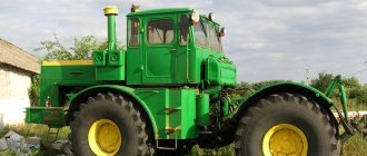
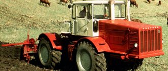
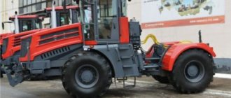
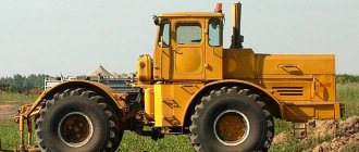
The Soviet-era Kirovets K-700 tractor was used for plowing, loosening a wide variety of soil, sowing, etc. By the end of the 60s, it began to be used in road and transport construction, earthmoving, and reclamation work. Kirovets was produced at the Kirov machine-building plant in Leningrad for more than 10 years. K-700A and K-701 are improved Kirovets models, fundamentally different from their prototype, which began to appear only in the early 70s.
Scope of application of the K-702 tractor
So, “K-702” is an industrial modification of the heavy energy-rich “Kirovets” tractor, with the purpose of using it as a loader, bulldozer, roller, scraper. Compared to the classic “Kirovets”, the “K-702” has a modified linkage system, only a hydromechanical transmission is used, and the suspension is rigid.
In accordance with the recommendations of the customer (Ministry of Defense), the tractor is capable of effectively performing the following special energy-intensive work in a short time: moving soil; rapid formation of transitions and crossings through ditches and ravines, exits to crossings; laying column tracks in areas overgrown with small forests and shrubs, saturated with stones and boulders, on virgin snow; clear roads of snow and level them from damage; dig pits in soils of categories 1-3.
Naturally, the K-702 tractor also performs “less special” operations in industry and construction very successfully and in the shortest possible time. Among them are digging pits and loading bulk, lump materials into vehicles; development and movement of soil during construction, repair and maintenance of roads, at construction sites; forming embankments and graders, filling ditches and holes, clearing areas and roads after heavy snowfalls. All this is, in general, business as usual for Kirovets.
The Kirovets K-702 tractor, or universal road machine (UDM-2), combines the functions of a loader and a bulldozer. This is a powerful, productive and multifunctional road construction equipment. A universal industrial tractor with an articulated frame is equipped with a front-end single-bucket loader TO-34 (PK-6) and a single-cylinder bulldozer. Blade type - hemispherical, with transverse distortion. The presence of a torque converter (GTR) maintains a favorable operating mode of the gearbox and engine when the machine is operating in the most difficult conditions.
Repair and tuning of K-700 tractors
Parts of the K-700, like any tractor, fail or break down, and therefore require maintenance or major repairs.
Tractor repair consists of the following:
- Valve adjustment is carried out for stable operation of the machine. The norm for thermal clearances of the valve mechanism is 0.25-0.30 mm. If the valve is incorrectly adjusted, this will affect the operation of the motor.
- Repair of the K-700 gearbox is carried out by replacing faulty parts.
- The relay is adjusted to maintain the voltage in the battery. It is important to correctly connect the electrical wires to the motor and pay attention to changes in the regulated voltage. For seasonal settings there is a Winter-Summer switch.
For Kirovets tractors, tuning was as follows:
- the tractor driver's cabin has been improved;
- the bumper and fenders were changed;
- tires were changed;
- engine replacement;
- modern hydraulic and pneumatic systems;
- replacement of electrical equipment and wiring.
For the K-700, tuning of the Kirovets tractor was carried out based on the needs and demand of consumers.
Technical characteristics of the K-702 tractor
Overall dimensions and weight parameters
- Tractor length – 8.9 m; Width – 3.1 m; Height – 3.8 m.
- In transport position, together with working equipment: Length – 10,250 m; Width – 3,360 m. Height is the same.
- Wheelbase - 3.75 meters.
- The turning radius is minimal, along the axis of the outer wheel, with the rear axle engaged - 8.8 meters.
- Ground clearance – 430 mm.
- The ford depth is 1 meter.
- Front/rear wheel track – 2.255 m.
- The greatest climb that can be overcome is 20 degrees.
- Operating weight – 20 tons.
- Total weight - 23 tons.
- The total weight distribution on the rear axle is 10.5 tons.
- Weight distribution on the front axle is 12.21 tons.
Tractor engine "K-702"
The K-702 tractor is equipped with a 4-stroke, 8-cylinder, V-shaped diesel engine YaMZ-238 ND3-1. This 14.87-liter engine is equipped with a turbocharging system and liquid cooling. Its rated power is 235 horsepower (or 173 kW). The nominal crankshaft rotation speed is 1,700 min-1. Specific fuel consumption at rated power is 218 g/kWh (160 g/hp/h). Pre-start heating of the engine is provided using the PZD-30 device. The fuel tank capacity is 320 liters.
The power unit, tested on a large number of special machines, has a number of undeniable advantages. In particular, he is loyal to diesel fuel that does not meet the modern level of quality. It also has excellent maintainability and, which is also important, does not have the slightest problem with spare parts.
YaMZ-238 diesel engines are used and very well known in absolutely all regions of Russia. To set up the fuel equipment, which is a classic in-line high-pressure fuel pump, ordinary mechanical stands are sufficient, and almost any service station will be able to sort out the fuel injection pump, replacing, if necessary, its individual sections.
Transmission, axles, steering and brake control "K-702"
The tractor is equipped with a manual transmission, also Yaroslavl, two-mode (working and transport modes), reversible, four-speed, with hydraulic gear shifting. The tractor transmission is equipped with a single-stage torque converter.
The number of gears in each mode is two forward and two reverse. The total number of gears is eight: four forward and four backward. Torque from the gearbox is transmitted to the sub-engine and cargo axles, which were developed in-house by the Leningrad enterprise.
All drive axles - both sub-engine and cargo - are equipped with differentials and planetary final drives. There is a differential and a self-locking freewheel. Thanks to this equipment, the tractor demonstrates high traction even on soft soils. Special tires with developed lugs also help to realize torque.
The Kirovets K-702 is equipped with 29.5/75R25 tires produced in Belarus (previously there were also deliveries from DneproShina, Ukraine). Tires designed for K-702 work in quarries differ significantly from the standard ones - they have a different tread pattern. There is also the possibility of additional tire protection with chains, which are offered as an additional option.
The cargo bridge has the ability to be turned off. This feature is very useful in a number of cases. In particular, when, for example, you need to transfer equipment from one object to another under your own power.
The steering of the loader is hydraulic, the steering column is adjustable. The service brakes are dry, shoe type with pneumatic drive. The parking brake is a shoe-disc brake with a pneumatic spring drive.
Tractor chassis and suspension; electrical equipment
The chassis of the “K-702” is wheeled, on pneumatic tires with a radial 22-layer tread. The wheels are single-pitch, discless. The suspension is balanced type on the sub-engine frame, and rigid on the portal frame.
The central hinge that connects the semi-frames deserves special mention. To be able to compensate for the wear of its parts, the designers provided a split pin, which is tightened as necessary during tractor maintenance. In addition, an additional external bushing is also introduced into the hinge - a kind of safety element that protects the “ears” of the frames in the event of large play in the hinge or when impact loads are applied to the metal.
The electric single-wire system of the K-702 tractor operates two 12-volt batteries with 190 ampere-hours each. The generator power is 2 kilowatts. The mains voltage is 24 Volts.
Front loader Kirovets K-702MA-PK6
The front-end single-bucket loader "Kirovets" K-702MA-PK6 is intended for use in loading and unloading operations with bulk and lump materials without preliminary loosening, for performing earthmoving and transport work on soils up to category III with unloading the material into a dump or vehicles. The loader can be used in construction, agriculture, land reclamation.
The use of jaw grips allows the loader to be used as a timber stacker for moving, stacking and performing loading and unloading operations at timber warehouses, logging, rafting and wood processing enterprises.
Specifications:
| WORK EQUIPMENT | K-702MA-PK6/LPK-6 | ||||
| Bucket load capacity, nominal, t | 6,0 | ||||
| Bucket capacity, cubic meters: | |||||
| — geometric | 3,0 | ||||
| — nominal | 3,5 | ||||
| Bucket cutting edge width, mm | 3100 | ||||
| Maximum height of bucket unloading along the cutting edge of the bucket at an unloading angle of 45°, not less, mm | 3260 | ||||
| Reach of the cutting edge of the bucket at maximum unloading height and unloading angle of 45°, mm | 1300 | ||||
| Bucket tilting angle at ground level, not less, degrees. | 40 | ||||
| Breakout force developed by hydraulic cylinders, kN(kgf): | |||||
| - arrows | 128,0 (12800) | ||||
| - ladle | 226,3 (22630) | ||||
| Limit angles, rad. (grad): | |||||
| — ascent (descent) | 0,35 (20) | ||||
| - roll | 0,21 (12) | ||||
| Maximum angle during operation, rad. (hail) | 0,0873(5) | ||||
| Bucket lifting time without load (at engine speed 1700 rpm), sec. | 10,7 | ||||
| CABIN | |||||
| Double, all-metal, with thermal, vibration and noise insulation, with a built-in safety cage that protects the operator from rollover of the machine (ROPS) and from falling objects (FOPS). Hydrostatic control of the loader's rotation, an adjustable steering column, and an instrument panel with automated control over the operation of the loader systems help reduce operator fatigue. Convenient location of controls, sprung driver's seat. Two fans for blowing front and rear windows, tinted windows. Two heaters. | |||||
| MAIN PARAMETERS AND DIMENSIONS | K-702MA-PK6/LPK-6 | ||||
| Machine base, mm | 3 750 | ||||
| Movement speed: | |||||
| — working, m/s (km/h) | 0…(7) | ||||
| — maximum, without load, m/s (km/h) | (39) | ||||
| — maximum, transport, m/s (km/h) | (30) | ||||
| Minimum turning radius, m | 8,8 | ||||
| Duration of continuous operation without refueling, hour. | 10,7 | ||||
| Overall dimensions, mm: | |||||
| - length | 8900 | ||||
| - width | 3100 | ||||
| - height | 3800 | ||||
| Weight, kg: | |||||
| - dry (structural) | 20000 | ||||
| — operational | 21000 | ||||
| Fuel tank volume, l | 320 | ||||
| ENGINE | |||||
| Model | YaMZ-238NDZ-1 | ||||
| engine's type | 8-cylinder, V-shaped diesel engine with turbocharging and water cooling | ||||
| Rated power, kW (hp) | 173 (235) | ||||
| Operating power, kW (hp) | 162 (220) | ||||
| Rated rotation speed, min.-1 | 1700 | ||||
| Maximum torque, Nm (kgfm) | 1108 (113,0) | ||||
| Engine displacement, l | 14,86 | ||||
| Specific fuel consumption, g/(kW×h) (g/(hp×h)) | 218 (160) | ||||
| Engine preheating | PZD-30 | ||||
| TRANSMISSION | |||||
| Type | hydromechanical | ||||
| Torque converter | single stage | ||||
| Transmission | mechanical | ||||
| Number of modes | two: worker and transport | ||||
| Switching modes | mechanical | ||||
| Number of gears in each mode | two forward and two back | ||||
| Total gears | eight: four forward and four backward | ||||
| Gear shift | mechanical control of the hydraulic gear shift system | ||||
| Drive axles | sub-engine and cargo with differentials and planetary final drives | ||||
| Differential | self-locking freewheel | ||||
| Freight bridge | switchable | ||||
| CHASSIS | |||||
| Suspension | Balanced on the sub-motor frame and rigid on the portal frame | ||||
| Industrial tires | 29.5/75R25 | ||||
| Rims | collapsible | ||||
| Service brakes | dry, block type with pneumatic drive | ||||
| Parking brake | block-disc with pneumatic spring drive | ||||
| ELECTRICAL SYSTEM | |||||
| Single wire | |||||
| Voltage, V | 24 | ||||
| Generator power, kW | 2 | ||||
| Accumulator battery | 2 x 12V x 190 A/h | ||||
| ADDITIONAL EQUIPMENT (optional) | |||||
| Air conditioner | |||||
| Quarry tires | |||||
| Autonomous cabin heater | |||||
Cabin of the K-702 tractor
The K-702 tractor is distinguished by a spacious two-seater sealed cabin. The cabin is all-metal, with decent modern thermal, vibration and noise insulation, with a built-in safety cage that protects the operator in the event of a machine rollover (“ROPS”) and from falling objects (“FOPS”). The operator’s workplace is equipped with the ability to regulate the thermal conditions and powerful ventilation. There are two heaters, two fans for blowing the front and rear windows, the windows are tinted.
The cabin of the K-702 tractor is characterized by a convenient location of the main controls and a sprung seat. A special instrument panel with automated control of the operation of the loader systems helps reduce operator fatigue during the work shift.
A characteristic feature of the operator’s workplace of the K-702 tractor is the presence of a reversible control post: the operator’s seat, together with the steering column, rotates 180 degrees within a minute.
Parameters of tractor working equipment (bulldozer and loading)
Loading:
The geometric capacity of the bucket is three cubic meters; nominal – 3.5 m3. The rated load capacity of the bucket is six tons. The maximum unloading height of the bucket along the cutting edge, with an unloading angle of 45°, is at least 3.26 meters. The width of the cutting edge is 3.1 m. The breakout force developed by the bucket hydraulic cylinders is 22.630 tons.
The maximum height of unloading of the bucket along the cutting edge, with an unloading angle of 45 degrees, is 3.2 m. The reach of the cutting edge of the bucket at the maximum height and unloading angle and unloading angle of 45 degrees is 1.3 m. The maximum operating angles of the loading bucket are - 20 degrees of ascent (descent) and 12 degrees of roll.
Bulldozer:
Width x Height of the bulldozer blade is: in bulldozer position – 3.36 m; in grader position – 3.23 m. Maximum blade depth – 520 mm; maximum lift – 1300 mm. Average blade lifting speed at 1700 rpm. is 0.37 m/s. Average blade lowering speed at 1700 rpm. – 0.3 m/s.
The angle of installation of the blade in the grader (left and right) position is 26 degrees. The blade lateral tilt angle is 11 degrees.
When laying column tracks, the K-702 tractor demonstrates the following performance: on moderately rough terrain: 2 km/h; on virgin snow with a meter depth of snow cover: 0.5-1 km/h. When filling holes and ditches: 120 cubic meters per hour. When digging pits - 85 cubic meters per hour. When loading bulk materials - 100 m3 per hour.
The time for transferring working equipment (blade or bucket) from transport to working position, or vice versa, is 60 seconds.
Optional equipment
As additional equipment options for the K-702 tractor (by separate order), it is possible to install the following standard equipment:
- The buckets are enlarged, with a capacity of up to 4.35 cubic meters; on the contrary, reduced, with a capacity of up to 2.6 cubic meters. And also double-jawed, with a capacity of up to 3 cubic meters.
- Jaw grippers (with a load capacity of 6 tons)
- Cargo forks (with a lifting capacity of 6 tons)
- Beamless crane booms (load capacity 6 tons)
- Special career tires.
The tractor cabin, also as an additional option, can be equipped with air conditioning.
During each maintenance, all existing grease nipples installed in the hinges must be bypassed with a grease fitting. In order not to waste time on this, you can order an automatic, centralized lubrication system, which is also offered as an option. A set of imported Lincoln equipment will cost a round sum of about a thousand euros.
Another useful additional option is the fuel tank heating system. Diesel fuel is heated by pipelines with coolant circulating through them from the liquid preheater circuit.
For large operating organizations, a system for monitoring the location of the machine is provided. If you add fuel consumption sensors to it, you can successfully combat unauthorized fuel drains.
Reviews about the K-702 tractor
As one of the most important advantages, many owners of this equipment and machine operators working on it note the ease of its operation and maintenance. All necessary maintenance actions can be performed by the operator and do not require additional training. The maintenance interval is 250 operating hours. For the hydraulic system, the interval between maintenance is 1000 operating hours.
The hood lids open wide, providing very convenient access to the engine. High pressure hoses and units are available for maintenance, replacement and repair.
The powerful “stove” inside the tractor deserves all praise. The seat is comfortable and, together with the steering column, simply rotates 180 degrees.
The hydraulics are equipped with simple and effective protection against dirt and snow. The central hinges have a gap compensation mechanism. The driveshaft is located high - it is simply impossible to damage it. The disconnectable cargo (front axle) allows you to save the units.
The 702nd “Kirovets” is good in operation: it “rows” vigorously with all four wheels, and picks up a lot in the bucket. But it is not always possible to work with very rocky or viscous soils as successfully as with ordinary ones.
Those who have gained experience working on both the K-702 and its imported “classmates” and can compare, oh, it’s a rather clumsy machine. This is a minus. The cabin of the K-702, in comparison with the “foreigners”, with all due respect to the Kirovets, still represents the “last century”. The tractor works great for the first three years, but then periodic problems begin, primarily with the steering. However, the disadvantages are offset by the relatively inexpensive “cost of ownership” of the tractor, the cheapness and availability (in terms of availability) of consumables, spare parts and other components.
UNIVERSAL ROAD MACHINE K-702MVA-UDM2
Transcript
1 "PETERSBURG TRACTOR PLANT" subsidiary of JSC "KIROVSKY PLANT" UNIVERSAL ROAD MACHINE K-702MVA-UDM2 Russia St. Petersburg
2
3 "PETERBURGSKY TRACTORNY ZAVOD" Ltd. subsidiary of "KIROVSKY ZAVOD" Co. VERSATILE ROAD-BUILDING MACHINE K-702MBA-UDM2 CATALOG OF PARTS Russia St. Petersburg
4
5 CONTENTS INTRODUCTION… 7 Fig. 1 Engine installation Fig. 2. Exhaust system Fig. 3. Power system Fig. 4. Fuel supply control Fig. 5. Engine cooling system Fig. 6. Water radiator Fig. 7. Expansion tank Fig. 8. Engine oil cooling system Fig. 9. Engine heating system Fig. 10. Air purification system Fig. 11. Air purifier Fig. 12. Semi-rigid coupling Fig. 13. Torque converter Fig. 14. Gearbox installation Fig. 15. Gear shift control Fig. 16. Selector Fig. 17. Gearbox control drive Fig. 18. Gearbox housing Fig. 19. Gearbox pump drive shaft Fig. 20. Drive shaft, clutch II reverse gear Fig. 21. Drive shaft, clutches of 2nd forward gear and 1st reverse gear Fig. 22. Drive shaft, clutch 1st forward gear Fig. 23. Intermediate shaft Fig. 24. Load shaft Fig. 25. Transfer shaft Fig. 26. Drive for controlling the transfer shaft clutches Fig. 27. Reverse axis Fig. 28. Gear shift mechanism Fig. 29. Gearbox pump Fig. 30. Transmission filter Fig. 31. Cardan transmission Fig. 32. Gearbox driveshaft Fig. 33. Front axle driveshaft Fig. 34. Gearbox pump cardan shaft Fig. 35. Frame joint cardan shaft Fig. 36. Intermediate support Fig. 37. Rear axle drive shaft Fig. 38. Front axle suspension Fig. 39. Rear axle suspension Fig. 40. Drive bridge Fig. 41. Main gear with differential Fig. 42. Hydraulic steering control system Fig. 43. Steering column Fig. 44. Hydraulic tank Fig. 45. Flow regulator
6 Fig. 46. Turning hydraulic cylinder Fig. 47. Hydraulic distributor Fig. 48. Wheel with tire Fig. 49. Brake system Fig. 50. Parking brake Fig. 51. Frame Fig. 52. Bulldozer equipment Fig. 53. Loading equipment Fig. 54. Cabin Fig. 55. Left door Fig. 56. Right door Fig. 57. Cabin accessories Fig. 58. Seat Fig. 59. Facing Fig. 60. Cabin ventilation and heating Fig. 61. Electrical equipment Fig. 62. Electrical equipment of the cabin Fig. 63. Engine electrical equipment Fig. 64. Instrument panel Fig. 65. Hydraulic system of loading equipment Fig. 66. Seals and bearings of hydraulic cylinders of loading equipment manufactured by SIA “Hidrolats” Fig. 66a. Seals and bearings of hydraulic cylinders of loading equipment produced by OJSC "Eletsgidroagregat" Fig. 67. Hydraulic system of bulldozer equipment Fig. 68. Elcont seals and bearings of hydraulic cylinders of bulldozer equipment Fig. 69. Reversible control station Fig. 70. Tools and accessories
7 CONTENTS INTRODUCTION… 9 Fig. 1. Mounting engine Fig. 2. Exhaust system Fig. 3. Fuel feed system 4. Fuel feed control 5. Cooling system of the engine 6. Water radiator Fig. 7. Expansion tank Fig. 8. Oil cooling system of engine…25 9. Heating system of the engine 10. Air cleaning system 11. Air cleaner 12. Semi-rigid coupling Fig. 13. Torque converter Fig. 14. Gearbox assembly Fig. 15. Gear shift control Fig. 16. Selector Fig. 17. Gearbox control drive Fig. 18. Gearbox crankcase Fig. 19. Gearbox pump drive shaft Fig. 20. Driving shaft, friction clutches of II-nd reverse gears Fig. 21. Driving shaft, friction clutches II-nd forward gears and I-st reverse gears Fig. 22. Driving shaft, friction clutches I-st forward gears Fig. 23. Intermediate shaft Fig. 24. Load-carrying shaft Fig. 25. Distributing shaft Fig. 26. Distribution shaft couplings control drive Fig. 27. Reversing axle 28. Gearshift mechanism Fig. 29. Gearbox pump Fig. 30. Gearbox filter Fig. 31. Cardan drive Fig. 32. Gearbox cardan shaft Fig. 33. Front axle cardan shaft Fig. 34. Gearbox pump cardan shaft Fig. 35. Joint frame cardan shaft Fig. 36. Intermediate support Fig. 37. Rear axle cardan shaft Fig. 38. Front axle suspension Fig. 39. Rear axle suspension Fig. 40. Driving axle Fig. 41. Main drive with differential Fig. 42. Hydraulic steering system 43. Steering column Fig. 44. Hydraulic tank Fig. 45. Flow regulator Fig. 46. Steering cylinder
8 Fig. 47. Hydraulic control valve Fig. 48. Wheel and tire Fig. 49. Brake system Fig. 50. Parking brake Fig. 51. Frame Fig. 52. Dozer equipment Fig. 53. Loading equipment 54. Cab Fig. 55. Left-hand door Fig. 56. Right-hand door Fig. 57. Cab accessories Fig. 58. Seat Fig. 59. Lining Fig. 60. Ventilation and heating cab 61. Electrical equipment 62. Cab electrical equipment 63. Engine electrical equipment 64. Dashboard Fig. 65. Hydraulic system of loading equipment 66. Sealing and bearings of loader cylinders SIA “Hidrolats” Fig. 66a. Sealing and bearings of loader cylinders Fig. 67. Hydraulic system of dozer equipment Fig. 68. “Elkont” seals and bearings of dozer's cylinders Fig. 69. Reverse control post 70. Tools and accessories
9 INTRODUCTION The catalog contains a range of parts and assembly units for the K-702MVA-UDM2 - a universal road machine, recommended for orders upon request. Assembly units and parts in the catalog are arranged in groups and subgroups, each of which has its own number, name and is accompanied by an illustration. Assembly units, parts and standard products are designated by serial position numbers. According to the accepted numbering system, the part number (assembly) of the K-702MVA-UDM2 machine, for example: 702MVA, is deciphered as follows: 702MVA - machine model number 17 - group number 15 - subgroup number own part number 1 - serial number of the part execution The text part of the catalog contains designations of assembly units, parts, numbers of illustrations that can be used when an assembly unit (part) is detected in the illustration. This machine contains components and assemblies that are also used in other tractor models, which is reflected in their designation. Be careful when placing orders for spare parts and correctly indicate their designations and names without any abbreviations. When ordering spare parts for the YaMZ-238ND3-1 engine, use the YaMZ engine catalog. 7
10 8
11 INTRODUCTION The Catalog covers the nomenclature of parts and assembly units to the K-702MBA- UDM2 versatile road building machine to be used for reference when drawing up orders. The assembly units and parts are divided in the Catalog into groups and subgroups, each of them being provided with a number, name and illustrations the assembly units, parts and standardized items are designated by ordinal numbers. According to the adopted numbering system the designation of the K-702MBA-UDM2 machine part, eg702mba l is decoded in the following way: 702MBA — machine model number; 17 - group number; 15 — subgroup number; part proper number; 1 — original number of the part version. The textual part of the Catalog contains the designation codes and names for the assembly units and parts, the illustration numbers, the references which can be used when finding the unit (or the part) drawing in the picture, or vice versa, when finding the unit (or the part) designation code by the reference in the illustration. This machine employs the same parts and assembly units as used in other models of tractors, which is reflected in their designation. Be attentive when drawing up orders for spare parts and give their designs and names without any contractions. When ordering a spare parts for engine YAMZ 238ND3-1e YAMZ engine catalogue. 9
12 Fig. 1. Engine installation Fig. 1.Mounting engine 10
13 Fig. 1 Engine installation Fig. 1. Mounting engine Pos. Designation Qty Name Name Ref. N Designation Qnt Traverse Beam Sleeve Hose Plank Plate Bushing A Bracket Bracket G Washer Washer 1 7. M20x1.5 Nut Nut 1 8. MM355 Sensor Gauge 1 9. M8x16 Bolt Bolt G Washer Washer G Washer Washer M27x X Bolt Bolt A Screw-in elbow Elbow Cone coupling Cone coupling Union nut Nut M8x20 Bolt Bolt A Pipe Pipe A Branch pipe Gasket B1 Compressor Compressor Clamp Clip Pipe Pipe A Pipe Pipe Screw-in fitting Pipe union Cone coupling Cone coupling Union nut Nut Pipe Pipe Clamp Clip ,5 Sleeve Hose Clamp Clip YaMZ-238ND3-1 Engine Engine M27x X Bolt Bolt Bolt A Spacer Gasket G Nut Nut M16x X Bolt Bolt AKSS-400M Shock absorber Shock-absorber M16x X Bolt Bolt G Washer Washer A Bracket Bracket Pipe Pipe Screw-in fitting Pipe union M16x X Bolt Bolt 2 11
14 Fig. 2. Exhaust system 2. Exhaust system 12
15 Fig. 2. Exhaust system 2. Exhaust system Pos. Designation Qty Name Name Ref. N Designation Qnt M12 Nut Nut Washer Washer Ring Ring Washer Washer Bracket Bracket Bushing Sleeve Tie Rod 1 8. M10x55 Bolt Bolt Tip Tip Clamp Clip Muffler Silencer M10x55 Bolt Clamp Clip Pipe Pipe M10 Nut Nut Gasket Gasket Branch pipe O-ring Sealing ring 2 13
16 Fig. 3. Power system Fig. 3. Fuel feed system 14
17 Fig. 3. Power system Fig. 3. Fuel feed system Pos. Designation Qty Name Name Ref. N Designation Qnt Fuel tank Fuel tank A Pipe Pipe Pipe Pipe Pipe Pipe 1 5. RNM-01 TU Pump RNM-1K Pump Pipe Pipe Pipe Pipe 1 8. Coarse filter Coarse fuel 1 cleaning filter Pipe Pipe A Pipe Pipe A Pipe Pipe A Pipe Pipe Pipe Pipe Pipe Pipe Pipe Pipe Pipe Pipe Pipe Pipe Pipe Pipe A Step Stair A Step Subdrumstick Clamping bolt Clamping bolt A5M-1.5 Gasket gasket A Clamping bolt A5M-1.5 Gasket gasket Pipe union fitting Blind nut Deaf nut A5M-1.5 Gasket gasket x17.5-1.5 Hose 3 sleeve (3×0.01m) x20-1.6 Hose sleeve x16.5-1.6 Hose sleeve M10x30 Bolt Bolt M8x20 Bolt Bolt 4 15
18 Fig. 4. Fuel supply control 4. Fuel feed control 16
19 Fig. 4. Fuel supply control 4. Fuel feed control 702MV Pos. Designation Qty Name Name Ref. N Designation Qnt Handle Handle Tie-rod Bolt Bolt Plate MV Tie-rod MV Pedal Pedal Bolt Bolt 2 8. M8x30 Bolt Bolt Tie-rod Accelerator MV Tie-rod Rod Lever shaft MV Tie-rod Rod Roller levers Lever shaft Rod Tie-rod MV Lever shaft Lever shaft Earring Clevis Spring Spring Stop drive Engine stop 1 drive Bolt Bolt Shaft MV Stop stop x28 Axle axis x18 Axle axis x25 Axle axis Washer Washer Washer Washer, 6×14 Cotter pin Cotter pin x20 Cotter pin 1 17
20 Fig. 5. Engine cooling system Fig. 5 Cooling system 18
21 Fig. 5. Engine cooling system Fig. 5. Cooling system of the engine 700A Pos. Designation Qty Name Name Ref. N Designation Qnt Radiator Radiator Strip Washer Washer Ring Ring Bushing Bushing Washer M12x55 Bolt Bolt M12x45 Bolt Bolt Washer Washer Norma Torro 40-60/9 Clamp Clip 12 DIN, 2x Cotter pin M12 Cotter pin Nut A Nut Expansion tank Elbow elbow Pipe Pipe Hose Pipe Pipe P Gasket P Pipe Branch pipe G Washer Washer Nut Nut Pipe Pipe Pipe Pipe Norma Torro 70-90/9 Clamp Clip 4 DIN A Elbow Elbow M12x30 Bolt Bolt M12 Nut Nut G.05 Washer Washer Tie Rod Fan casing Fan cover Bracket Bracket Bracket 1 19
22 Fig. 6. Water radiator Fig. 6.Water radiator 20
23 Fig. 6. Water radiator Fig. 6. Water radiator Pos. Designation Qty Name Name Ref. N Designation Qnt Trim Strap Lower tank of radiator Strip Strip Gasket Elbow Elbow Gasket Right side Right side Upper radiator tank Upper tank of radiator Left side Left side Radiator core Radiator core 1 21
24 Fig. 7. Expansion tank Fig. 7. Expansion tank 22
25 Fig. 7. Expansion tank Fig. 7. Expansion tank 700A Pos. Designation Qty Name Name Ref. N Designation Qnt A Expansion tank Cover Cover Plug Plug Gasket Gasket Air-steam valve 1 steam-air Gasket 1 23
26 Fig. 8. Engine oil cooling system Fig. 8. Oil cooling system of engine 24
27 Fig. 8. Engine oil cooling system Fig. 8. Oil cooling system of engine Pos. Designation Qty Name Name Ref. N Designation Qnt Gasket gasket Right side plate Oil radiator Oil radiator Bottom x28-1.6 Sleeve Hose 4x0, Gasket gasket À Branch pipe 2 8. M8x20 Bolt Bolt Pipe Pipe Pipe Pipe Left side plate Left side plate Curtain assembly Curtain assembly Strap M8x16 Bolt Bolt Plate À Cover Cover Roller Roller Bracket Cramp Washer Washer M10x25 Bolt Bolt Cable Cable Ring Chain Chain Bush Norma Torro 20-32/9 DIN3017 Clamp Clip 8 25
28 Fig. 9. Engine heating system Fig. 9. Heating system of the engine 26
29 Fig. 9. Engine heating system Fig. 9. Heating system of the engine 702MV Pos. Designation Qty Name Name Ref. N Designation Qnt Pipe MV Pipe Pipe Branch pipe Branch pipe Pipe Pipe Fuel tank Fuel tank Faucet Cock Tape Ribbon Filler neck Aperture jellied Pipe Pipe A Pipe Pipe P Pipe Pipe P Pipe Pipe MV Frame P Tape Ribbon P Pipe Pipe P Nozzle Tip Pipe Pipe Pipe Pipe Gasket Screw Screw A Cramp Bracket A Cramp Bracket Hose P Pipe Pipe P Pipe Pipe P Pipe Pipe P Pipe Pipe P Hose P Hose P Hose P Hose P Corner Angle Cover Cover Gasket Gasket Stopper M8x16 Bolt Bolt M8x20 Bolt Bolt M8x30 Bolt Bolt M10x30 Bolt Bolt M8 Nut Nut M12x1.25 Nut Nut G.05 Washer G.05 Washer G.05 Washer Washer 1 27
30 28
31 Washer Washer Washer Washer Clamp Clip Clamp Clip Clamp Clip Clamp Clip ,0 Bracket Cramp ,0 Bracket Cramp Nut Coupling Coupling A Drain valve Cock PZD30G Heater Heater x16.5-1.6 Sleeve Hose 0.08 m x17.5-1 .5 Hose Sleeve 0.2 m (2x0.1 m) x56.5-1.47 Hose Sleeve 0.08 m x61.5-1.57 Hose Sleeve 0.08 m C 10.0x2.0 Pipe Tube 0.06 m (2x0.03m) MV Spacer Gasket 4 29
32 Fig. 10. Air purification system Fig. 10. Air cleaning system 30
33 Fig. 10. Air purification system Fig. 10. Air cleaning system Pos. Designation Qty Name Name Ref. N Designation Qnt Air intake pipe Pipe Flange Flange Branch pipe Pipe Pipe P Clamp Clip Air cleaner Air cleaner Clogging alarm Indicator 1 Air cleaner specifications Air cleaner cyclonic 1 cyclone Pipe Pipe Pipe Pipe P Clamp Clip P Gasket Bushing Bushing M8x30 Bolt Bolt M12x25 Bolt Bolt M12x55 Bolt Bolt M12 Nut Nut G.05 Washer Washer G.05 Washer Washer Washer Washer Washer Washer Clamp Clip Clamp Clip Cramp x925 Hose Sleeve x56.5-1.4 Hose Sleeve 1 (0.2 m) x61.5- 1.6 Sleeve Hose 3 (3x0.2 m) 31
34 Fig. 11. Air purifier 11. Air cleaner 32
35 Fig. 11. Air purifier 11. Air cleaner Pos. Designation Qty Name Name Ref. N Designation Qnt Air cleaner Air cleaner cyclonic 1 cyclone Air cleaner Air cleaner 1 3. Housing 1 4. T * Filter element 2 5. Washer 2 6. Washer 2 7. Nut Nut 1 8. T ** Filter element element 1 9. Cover Cover Wing nut Nut-lambskin 1 * Can be replaced with Filter element ** Can be replaced with Filter element 33
36 Fig. 12. Semi-rigid coupling Fig. 12. Semi-rigid coupling 34
37 Fig. 12. Semi-rigid coupling Fig. 12. Semi-rigid coupling elastic coupling Pos. Designation Qty Name Name Ref. N Designation Qnt Bolt Bolt Disk Disk 1 3. M12 Nut Nut Washer Washer Bushing Bushing Shock Absorber Shock 12 Absorber Outer coupling Outside coupling Inner coupling Inside coupling Ring C200 Ring Ring Coupling Coupling Ring 1 35
38 Fig. 13. Torque converter Fig. 13. Torque converter 36
39 Fig. 13. Torque converter Fig. 13. Torque converter Pos. Designation Qty Name Name Ref. N Designation Qnt Housing Housing Shaft-drum Shaft-drum Drum Drum Turbine wheel Wheel turbine Guide vane I Device directing I Hub Hub Guide vane II Device directing II Pumping wheel Wheel pump A Bushing A Coupling Coupling Gear Gear Carter Gear case A Coupling Cup SLEEVE NSh100A-3-LSS PUMP Workshop Washer gear Gear Hubs Hubs Hub of Directing 1 Device Device Ring Packing Ring Cover Cover and Cuff 75x100 Collar Ring Ring Flanger Flang Ring Ring Ring Ring Ring Ring Ring Ring Ring Ring Ring Ring Ring Ring Ring Ring Ring Ring Ring Ring Ring Ring Ring LANGE COVER COUFT COUPLING NMSH25 PUMP pump and glass SLEEVE Branch pipe Plug Plug Bushing Nut Nut Drum Drum Ring (adjusting) Ring Flange x135-4 Cuff Collar Oil receiver Oil intake Cover Cover Ring 1 37
40 38
41 Flange Flange Coupling Coupling Cover Cover C200 Ring Ring Elastic coupling Coupling A Branch pipe Branch pipe Pipe Pipe Stud Stud Eye nut Eye nut A Angular coupling Coupling angular Ring Ring Pipe union fitting Valve Pipe union fitting Plug Plug Plug Plug Clamping bolt Clamping bolt Pipe Pipe Cover Cover Roller Shaft Flange Flange x70-3 Collar Cup Sleeve A Bearing Bearing Bearing Bearing Bearing Bearing Bearing Bearing Bearing Bearing Bearing Bearing Bearing Bearing 1 39
42 Fig. 14. Installation of gearbox Fig. 14. Gearbox assembly 40
43 Fig. 14. Installation of gearbox Fig. 14. Gearbox assembly MV Pos. Designation Qty Name Name Ref. N Designation Qnt Clamping bolt Clamping bolt Filter Oil filter Pipe Pipe 1 4. M8x35 Bolt Bolt A Sleeve Hose Safety valve Valve A Pipe Pipe Ring Ring 1 9. NSh 10-3-A Pump Pump M8x30 Bolt Bolt Gasket M10x40 Hairpin Stud Cover Cover Bracket Bracket Gasket A Cap Cap A Gasket A absorber М22х Х Bolt М14х Х Bolt Bolt Gearbox in Gearbox assembly 1 assembly Clamping bolt М10х55 Stud stud Pipe Pipe Sleeve Hose Washer Washer A Bracket Bracket Pressure sensor Oil pressure 1 gauge 41
44 42
45 M20x1.5 Nut Nut Gasket Gasket Gasket Valve Valve Valve Valve 1 43
46 Fig. 15. Gear shift control Fig. 15. Gear shift control 44
47 Fig. 15. Gear shift control Fig. 15. Gear shift control Pos. Designation Qty Name Name Ref. N Designation Qnt MV Selector MV Rod Tie-rod Roller Shaft Lever Lever Pin Pin Rod Tie-rod Shift mechanism Gearshift mecha- 1 gear nism Lever Lever Bracket Bracket C 10.0x2.0 Tube Pipe 1 45
48 Fig. 16. Selector Fig. 16. Selector 46
49 Fig. 16. Selector Fig. 16. Selector 702MV Pos. Designation Qty Name Name Ref. N Designation Qnt MV Lever MV Spring Spring MV Plate Plate 1 4. M6 Bolt Bolt G.05 Washer Washer 2 6. Ш6 Bearing Bearing MV Lever Lever A Spring Spring Washer Washer MV Carrier Carrier MV Base Base plate MV Axle Axle M5x12 Screw Screw G.05 Washer M8 Nut Nut G.05 Washer u8x40 Pin Pin MV Casing Case MV Lever Lever 1 47
50 Fig. 17. Gearbox control drive Fig. 17. Gearbox control drive 48
51 Fig. 17. Gearbox control drive Fig. 17. Gearbox control drive 702MV Pos. Designation Qty Name Name Ref. N Designation Qnt Clamp Hold-down plate Spring Spring Washer Washer Bushing x40 Cotter pin Cotter pin Cover Cover Gasket Lever Lever u8x25 Pin Pin Axle Axle Support Support М8х25 Bolt Bolt Cover MV Lever Handle Handle М10х30 Bolt Bolt М6х12 Bolt Cover Cover Gasket Gasket Gasket Neck B11, Ball Ball Carrier Leash Carrier Leash Carrier Ring Gasket Gasket Housing Housing B9, Ball A Spring Spring Screw Screw Stop Stop Washer Washer Washer Washer Adjusting screw Adjusting screw Bushing Bushing Bushing Bushing Stop Stop M8x16 Bolt Bolt 4 49
52 Fig. 18. Gearbox housing Fig. 18. Gearbox crankcase 50
53 Fig. 18. Gearbox housing Fig. 18. Gearbox crankcase is included in Pos. Designation Qty Name Name Ref. N Designation Qnt Tight-fitting bolt 2 2. FT 28x34x1 Gasket Plug Gasket Gasket Clamping bolt Bolt Pipe Pipe À Pipe Pipe À Plug Plug À Spring B20, Ball Ball À Valve housing Pipe Pipe Clamping bolt Bolt FT 12x18x1 .5 Gasket M8x20 Bolt Bolt Washer Washer Bushing Bushing Gasket À Pin Pin Carter (upper half) Gearbox crankcase, 1 upper half Pin G Washer Washer Eye nut Eye nut Gasket Gasket Gasket Gasket Gasket Gasket G Washer M10x25 Washer Bolt Bolt Pipe M14x1.5 Nut Nut M10 Nut Nut Cover Cover Gasket M10x20 Bolt Bolt M10x22 Stud A Cover Cover Gasket A Stud Stud Stud Stud M14x1.5x60 Bolt Bolt A Valve Valve 1 51
54 Fig. 19. Gearbox pump drive shaft Fig. 19. Gearbox pump drive shaft 52
55 Fig. 19. Gearbox pump drive shaft Fig. 19. Gearbox pump drive shaft is included in Pos. Designation Qty Name Name Ref. N Designation Qnt Gasket 1 2. M16x32 Bolt Bolt Washer Washer Ring Flange Flange A Bearing Bearing Housing Housing A Gasket Shaft AC9 Bearing Bearing x70-3 Collar Gear Gear B90 Ring Ring u8x18 Pin Pin A Sleeve Cup A Bearing B62 Ring Ring Bushing A Gear Gear Gasket Spacer M12x50 Bolt Bolt Gasket Spacer A Housing Housing A Gear Gear Gasket Spacer Gasket Spacer A Shaft Shaft B20 Ring Bearing Bearing Shaft Shaft M12x30 Bolt Bolt Pin Pin M10x20 Bolt Bolt Cover Cover 1 53
56 Fig. 20. Drive shaft, clutch II reverse gear Fig. 20. Driving shaft, friction clutches of II-nd reverse gears 54
57 Fig. 20. Drive shaft, clutch II reverse gear Fig. 20. Driving shaft, friction clutches of II-nd reverse gears Pos. Designation Qty Name Name Ref. N Designation Qnt Screw Screw Nut Nut O-ring Packing ring Washer Washer Pulley Pulley A Cuff 75x100x10 Collar A Flange A Gasket A Ring A O-ring Packing ring Collar Collar Collar A Ring A Ring Ring O-ring Packing ring Bushing A Clip Holder A Gasket KM Bearing Bearing C130 Ring Ring Intermediate ring Intermediate 1 ring KM Bearing Bearing C110 Ring A Gear Gear Ring Ring Intermediate ring Ring Drum Drum C180 Ring Drum left Left-hand drum O-ring Packing ring Sleeve glass A Spring Spring Disk Disk A Disk Disk Pressure disk A O-ring Packing ring A Left disk Left-hand disk A Ring Cuff Collar Right disk Right-hand disk A Bearing 2 55
58 56
59 C215 Ring A Ring A Ring Gear Gear A Bushing 1 57
60 Fig. 21. Drive shaft, clutches of 2nd forward gear and 1st reverse gear 21. Driving shaft, friction clutches II-nd forward gears and I-st reverse gears 58
61 Fig. 21. Drive shaft, clutches of 2nd forward gear and 1st reverse gear 21. Driving shaft, friction clutches II-nd forward gears and I-st reverse gears Pos. Designation Qty Name Name Ref. N Designation Qnt Drum Drum C80 Ring Drum middle Drum middle Sealing ring Packing ring Disk Disk A Disk Disk Pressure disk Sealing ring Packing ring A Disk middle Disk middle A Ring Ring A Packing ring Cuff Collar M6x55 Bolt Bolt A Cover Cover A Ring Ring O-ring Packing ring Bushing A Spring Spring Cup Sleeve Spring Spring A O-ring Packing ring Oil pipe Oil pipe Drive shaft Driving shaft K Bearing Bearing A Middle support Intermediate 1 support Gear Gear Drive shaft Driving shaft 1 59
62 Fig. 22. Drive shaft, clutch 1st forward gear Fig. 22. Driving shaft, friction clutches I-st forward gears 60
63 Fig. 22. Drive shaft, clutch 1st forward gear. Fig. 22. Driving shaft, friction clutches I-st forward gears Pos. Designation Qty Name Name Ref. N Designation Qnt A Bushing Bushing A Bearing Bearing A Ring Ring C125 Ring Ring Disk Cuff Collar A Ring Ring A Disk right Left-hand disk Packing ring Pressure disk A Spring Spring Cup Sleeve O-ring Packing ring Disk A Disk Disk Drum left Left-hand drum Gear Gear KM Bearing Bearing Intermediate ring Intermediate 1 ring Spacer ring Ring C110 Ring Ring Spacer bushing Bushing A Gasket Gasket Support Support O-ring Packing ring Bushing ring KM Bearing Bearing A Ring A O-ring Packing ring Cuff Collar A Cuff Collar A Ring A Ring A Left-hand holder A Cuff 75x100x10 Collar A Flange Washer Washer O-ring Packing ring Nut Nut Screw Screw 1 61
64 Fig. 23. Intermediate shaft Fig. 23. Intermediate shaft 62
65 Fig. 23. Intermediate shaft Fig. 23. Intermediate shaft Pos. Designation Qty Name Name Ref. N Designation Qnt Ring Ring 1 2. M12x35 Bolt Bolt A Cover Cover A Gasket Nut Nut Bearing Bearing A Clip Holder KM Bearing Bearing 2 9. B100 Ring Gear Gear Bushing Gear Bushing Gear Gear Ring Ring Half-Ring Half-Ring Gear Bushing Bushing Intermediate shaft Intermediate 1 shaft Cover Cover Gasket Bearing Bearing Bushing Bushing Clip Holder A Gear Bearing B-45 Ring Ring Intermediate shaft Intermediate shaft 1 63
66 Fig. 24. Load shaft Fig. 24. Load-carrying shaft 64
67 Fig. 24. Load shaft Fig. 24. Load-carrying shaft Pos. Designation Qty Name Name Ref. N Designation Qnt Half-Ring Ring K5 Bearing Bearing A Bushing Bushing Gear 1 6. M12x35 Bolt Bolt A Cover Cover Gasket Nut Nut AK Bearing Bearing A Clip Holder Gear A Gear Gear Gear Gear Cargo shaft Load-carrying 1 shaft KM Bearing Bearing Bushing 1 65
68 Fig. 25. Transfer shaft Fig. 25. Distributing shaft 66
69 Fig. 25. Transfer shaft Fig. 25. Distributing shaft Pos. Designation Qty Name Name Ref. N Designation Qnt A Nut Nut O-ring Packing ring A Flange A Ring 2 5. M12x25 Bolt Bolt G Washer Washer Clip Holder Gasket x135-4 Collar K2 Bearing Bearing B160 Ring A Ring Ring Bearing B140 Ring A Ring Ring Gear A Clutch Clutch Spring Spring Retainer Lock Clutch Bearing Bearing B150 Ring A Ring Ring A Gear Gear Ring Ring Transfer shaft Distributing 1 shaft /50 Bearing Bearing Bushing Bushing Clip Holder Retaining ring Ring M12x30 Bolt Bolt A Bearing Bearing B180 Ring Half-ring Half-ring Mobile gear coupling Moveable gear 1 clutch A Shaft Shaft A Bearing Bearing Gasket u8x18 Pin Pin A Cover Cover 1 67
70 Fig. 26. Drive for controlling the transfer shaft couplings Fig. 26. Distribution shaft couplings control drive. 68
71 Fig. 26. Drive for controlling the transfer shaft couplings Fig. 26. Distribution shaft couplings control drive Pos. Designation Qty Name Name Ref. N Designation Qnt M8x16 Bolt Bolt G Washer Washer Cover Cover Gasket Gasket 2 5. M10x20 Bolt Bolt A Washer Washer Housing Housing Gasket Gasket M10x30 Bolt Bolt Lever Fork Fork Cracker Block Set screw Screw adjusting Fork Fork Pin Pin T6 Oil can Oilcan Bracket Bracket Strip Strip Lever lever bushing Bushing, 2x20 Shplint Cotter PIN Bushing Bushing, 5x16 Shplint Cotter Pin EXTENT TIE-ROD ASSEMBLY M14 GUKE TIE-ROD SHAFT TIE-ROD BALANCER BALANCER BALANCER BLOCKER BLOCKAR BLOKK GAKE GAKE GAKE NUS PLUG FT10x16x1 gasket Gasket C20 Ring Ring Cover Cover Balancer Balancer Roller with head Shaft G Washer Washer M10 Nut Nut Housing Housing A Plug Plug 2 69
72 70
73 Roller Shaft Ring Washer Washer M10x40 Bolt Bolt Bushing Bushing Shaft M10x25 Bolt Bolt M10x45 Bolt Bolt 2 71
74 Fig. 27. Reverse axis Fig. 27. Reversing axle 72
75 Fig. 27. Reverse axis Fig. 27. Reversing axle Pos. Designation Qty Name Name Ref. N Designation Qnt Gasket A Cover Cover G.05 Washer Washer 4 4. M12x25 Bolt Bolt A Axle Axle Ring Ring KM Bearing Gear Gear 1 9. B100 Ring A Ring Ring 1 73
76 Fig. 28. Gear shift mechanism Fig. 28. Gearshift mechanism 74
77 Fig. 28. Gear shift mechanism Fig. 28. Gearshift mechanism Pos. Designation Qty Name Name Ref. N Designation Qnt Housing Housing Liner À Spool Slide valve Carrier O-Ring u8x12 Pin Pin À Gasket Gasket À Plug Plug Gasket À Plug Plug Plug Plug À Plug Plug Gasket À Spool Slide valve Lever M8x30 Bolt M1 0x30 Bolt Bolt À Bracket À Gasket Spring Spring B9, Ball Ball M10x25 Bolt Bolt Plug Plug u8x18 Pin Pin Cover Cover À Rail Rack À Plug Plug u8x8 Pin Pin Spool Slide valve Slide valve À Stop Stop Ring 1 75
78 Fig. 29. Gearbox pump Fig. 29. Gearbox pump 76
79 Fig. 29. Gearbox pump Fig. 29. Gearbox pump 700A Pos. Designation Qty Name Name Ref. N Designation Qnt A Gasket Gasket A Gasket Gasket A Gasket Gasket A Oil intake Oil intake A Gasket 1 gasket 6. NMSh-25 Pump Pump A Plate A Pipe A Pipe A Gasket gasket A Tray pan A Plug Plug М10х40 Stud pin М10х20 Hexagon bolt М12х110 Bolt Bolt M12x65 Bolt Bolt M8x14 Bolt Bolt A Turning elbow Gasket gasket Clamping bolt Clamping bolt Gasket gasket Washer Washer G.05 Spring washer 4 77
80 Fig. 30. Transmission filter Fig. 30. Gearbox filter 78
81 Fig. 30. Transmission filter Fig. 30. Gearbox filter Pos. Designation Qty Name Name Ref. N Designation Qnt Valve Valve Spring Spring Rod Rod Bushing Bushing Spring Spring Ring Contact Сontact Bushing Bushing Gasket Plug Plug M5 Nut Nut Ring Base Base plate Gasket A Plug Plug Filter section section Section of the filter 23 assembly Bushing bushing Washer Nut Housing Housing 1 79
82 Fig. 31. Cardan transmission Fig. 31. Cardan drive 80
83 Fig. 31. Cardan transmission Fig. 31. Cardan drive Pos. Designation Qty Name Name Ref. N Designation Qnt Cardan shaft Joint frame cardan 1 frame shaft Rear cardan shaft Rear axle cardan 1 axle shaft Intermediate support Intermediate 1 support Flange Flange Stop plate Stop plate 3 6. М12х Х Bolt Bolt Clamp Hold-down plate Front axle car cardan shaft - 1 axle dan shaft Cardan shaft Gearbox cardan 1 gear shaft Cardan shaft pump Gearbox pump with 1 gearbox ardan shaft Bolt Bolt M8x25 Bolt Bolt 8 81
84 Fig. 32. Gearbox driveshaft Fig. 32. Gearbox cardan shaft 82
85 Fig. 32. Gearbox driveshaft Fig. 32. Gearbox cardan shaft Pos. Designation Qty Name Name Ref. N Designation Qnt М8х16 Bolt Bolt Plate Plate Balance plate Balance plate Balance plate Balance plate Bearing cover Bearing cover Double hinge fork Fork A Flange Flange Cross K4С10 Bearing Bearing 8 83
86 Fig. 33. Front axle driveshaft Fig. 33. Front axle cardan shaft 84
87 Fig. 33. Front axle driveshaft Fig. 33. Front axle cardan shaft Pos. Designation Qty Name Name Ref. N Designation Qnt Bolt Bolt Stop plate Stop plate Balancing plate Balance plate Balance plate Balance plate Balance plate Balance plate Bearing cover Bearing cover Shaft Shaft Ring Flange-fork Fork-flange Sliding fork Slide fork Cardan cross Cross of cardan 2 shafts shaft Clip assembly Holder assembly O-ring Packing ring K5 Bearing Bearing 8 85
88 Fig. 34. Gearbox pump cardan shaft Fig. 34. Gearbox pump Cardan shaft 86
89 Fig. 34. Gearbox pump cardan shaft Fig. 34. Gearbox pump cardan shaft Pos. Designation Qty Name Name Ref. N Designation Qnt Flange cardan fork Flange fork Cardan cross with Sealed cross 2 oil seal Bearing retaining ring Stop ring 8 cardan K6US10 Bearing bearing Balancing plate Balance plate Cardan shaft 1 87
90 Fig. 35. Frame hinge drive shaft Fig. 35. Joint frame cardan shaft 88
91 Fig. 35. Frame hinge drive shaft Fig. 35. Joint frame cardan shaft Pos. Designation Qty Name Name Ref. N Designation Qnt Bolt Bolt Stop plate Stop plate Balance plate Balance plate Balance plate Balance plate Balance plate Balance plate Bearing cover Bearing cover Cardan cross Center cross of 2 shafts cardan shaft Flange-fork Fork-flange Double-joint fork Yoke of univer - 1 joint Holder assembly O-ring Packing ring K5 Bearing 8 89
show more

