Components of the mechanism
In KAMAZ 43118, the gearbox has a two-stage design and is equipped with an electro-pneumatic lock.
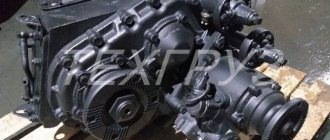
The KAMAZ transfer case structure includes the following elements:
- Drive shaft.
- Center differential with lock.
- Drive shafts of front and rear axles.
- Gear transmissions.
- Downshift.
- Cast metal housing (crankcase) filled with lubricant.
KAMAZ 43118 transfer case diagram
The KAMAZ 43118 transfer case is installed behind the gearbox, one side on the side member of the vehicle frame and the other side on a beam located between the cross members.
The differential is locked using a pneumatic system, the control drive of which is located in the driver's cabin.
The three-way control valve has three positions - neutral, first and second gear. The crankcase has an installation hatch in the upper part through which the power take-off is installed.
Oil is filled through a special hole, normally closed with a plug. A winch is attached to the output shaft splines.
Transfer case control
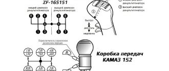
The transfer case is controlled by a pneumatic valve, the handle of which is located on an additional panel under the instrument panel (see Fig. Transfer case gear shift valve handle).
Transfer case shift valve handle
The gear shift valve handle has three fixed positions, each of which corresponds to a transfer case gear: N – neutral. Bridges are disabled. I - the handle is turned to the right, the first (low) gear is engaged. At the same time, the downshift indicator light on the instrument panel lights up. Engage the first (lowest) gear before driving along difficult sections of the road, as well as when parking the car for long periods. II – the handle is turned to the left – the second (highest) gear is engaged. Engage the second (highest) gear before driving on paved roads.
Attention! You can change gears only after the car has come to a complete stop and with the gear shift lever in the neutral position in the gearbox. Engaging neutral in the transfer case while the engine is running and the gear in the gearbox is engaged is prohibited.
If the pneumatic system fails, it is possible to force a gear shift in the transfer case (see section 7 “Possible malfunctions of vehicle units and systems. Self-help”).
The transfer case center differential lock is controlled pneumatically by a handle located on an additional panel under the instrument panel. The lock should be turned on immediately before overcoming difficult sections of the route (sticky soil, obstacles, slippery muddy roads).
Attention! Activation of the transfer case center differential is allowed only after the vehicle has come to a complete stop and with the gear shift lever in the gearbox in neutral position. The transfer case center differential lock must be disabled immediately when driving onto a hard, dry road, since driving with the lock engaged on a hard road can lead to damage to the transfer case parts.
Handle for controlling the locking of the center differential of the transfer case
The tap handle has two fixed positions:
- locking enabled - right position 1;
- locking is off - left position 2.
When the lock is turned on, the indicator lamp for turning on the center differential lock of the transfer case lights up on the instrument panel and lights up while the differential is locked. If the control lamp does not light up, you must:
- turn off the lock by setting the center differential lock control valve handle to position 2;
- carefully move the car forward 0.5-1 meter. If there is no traction, turn the drive wheels;
- turn on the locking by setting the tap handle to position 1. Then move away smoothly, without jerking, to reduce wear on the teeth of the locking clutch.
Attention! Driving a vehicle with the transfer case center differential lock engaged is only allowed when the warning light is on.
Basic principles of operation of the transfer case in a KAMAZ vehicle
The KAMAZ 43118 transfer case transfers power to the drive shaft of rotational motion and transfers power to the distribution box in which the center differential (MO) is installed. There are three types of MO:
- Friction clutch.
- Viscous coupling (viscous coupling).
- Self-locking differential Torsen model. Structurally, it is a worm gear; torque is transmitted due to friction.
Friction clutch in KAMAZ 43118. It is a set of disks, the adhesion density of which to each other is determined by the rotation conditions. Slipping of any axle causes the discs to compress and the clutch to lock, as a result of which the axle with the greatest degree of traction receives power.
Viscous coupling in KAMAZ 43118. A set of perforated discs placed in a silicone mass. Half of them are connected to the body, the other to the hub. Slipping of one of the axles causes locking and binds the hub and clutch housing.
Of all types of MO, the viscous coupling is the most popular; it is simple and reliable in operation.
Drive wheel drive of the KamAZ-4310 vehicle
Nbsp; Neftekamsk Automobile School “Voluntary Society for Assistance to the Army, Aviation and Navy of Russia” ===================================== ===================== LECTURE on the discipline “DEVICE AND MAINTENANCE
VEHICLE"
Topic No. 4. Design, purpose and operation of the transmission
Lesson No. 4.6. Cardan transmissions and drive axles
for training specialists in VUS-837 “drivers of category “C” vehicles”
Neftekamsk 2017
Topic No. 4. Design, purpose and operation of the transmission (SLIDE No. 1)
Lesson No. 4.6. Cardan transmissions and drive axles
Study questions (SLIDE No. 2)
- Purpose, design and operation of cardan transmission and drive axle drives.
- Purpose, design and operation of the drive axle.
- Main gear, differential.
- Typical malfunctions, their symptoms, causes and solutions.
Time:
2 hours.
Location:
audience.
Type of lesson:
lecture.
Methodical instructions.
Justify to students the importance of the educational issue under consideration. The main provisions should be written down in the notes.
Give specific examples from car operating experience.
Pay attention to the correct note-taking.
Present educational material using frames in Microsoft PowerPoint, diagrams and posters.
Maintain connection with the audience.
Quality control of learning material is carried out by a short survey on the material presented.
Summarize the issue discussed and proceed to present the next educational issue.
Draw conclusions based on the lesson material, summarize the lesson, answer students’ questions. Give a task for independent work.
Introduction
The speed of a vehicle largely depends on the technical condition of the cardan transmission and drive axles. Choosing the right speed mode is the key to saving fuel. The gearbox together with the engine, as well as the transfer case, are attached to the frame through rubber cushions, and the drive axles are connected to the frame through springs. When the load changes or when driving on uneven roads, the distance and angles between these units change. Under these conditions, the cardan transmission allows uninterrupted transmission of torque.
The drive axle mechanisms increase torque and transmit it to the axle shafts at right angles, and the cross-axle differential allows the wheels of one axle to roll at different speeds when cornering or on uneven roads.
Study Question #1.
Purpose, design and operation of cardan transmissions and drives
Drive wheels
The connection of successively located drive and driven shafts of one mechanism, and even more so of several units located at a distance from each other and changing their relative positions in the process of transmitting torque, presents significant difficulties due to the need to ensure strict coaxial rotation of the mentioned parts. When transmitting torque, misaligned and rigidly connected shafts experience significant radial, axial and inertial loads, which are transmitted to their supports and fastening parts and lead to premature destruction of these components and parts.
The gearbox (together with the engine) and the transfer case are located at a certain distance from each other and have a semi-rigid attachment to the car frame, and the main gears are located even further away from them and, in addition, are equipped with an elastic connection to the car frame, i.e. The main gear can change its position to a greater extent both relative to the frame and relative to the above-mentioned units.
Thus, the shafts, which must be connected to each other to transmit rotation (torque) from one of the above-mentioned units to another, initially have misalignment and inconsistency in their relative positions while the car is moving. Consequently, conventional shafts are not suitable for the power connection of the gearbox with the transfer case and final drive.
Taking into account the above, a special unit is used in the machine’s transmission, which allows, when transmitting significant torques, to compensate for the misalignment of the driven and drive shafts of the connected units, as well as the changing difference in distances between them. This unit is called a cardan drive.
1.1. Cardan transmission.
The cardan transmission is used to transmit torque from the driven shaft of the gearbox or transfer case to the drive shaft of the main gear.
Its use is due to the fact that the relative position of the axes of the transmission shafts changes, and they do not lie on the same straight line. (SLIDE No. 4)
For three-axle vehicles KamAZ-4310 and Ural-4320, the cardan transmission consists of the main driveshaft (between the gearbox and transfer case), the middle axle drive shaft, the rear axle drive shaft and the front axle drive shaft.
The gearbox or transfer case on a car is installed above the drive axle, as a result of which the axis of the driveshaft transmitting torque is located at a certain angle to the horizontal. The gearbox is fixedly connected to the frame, and the drive axle is suspended from it using springs. When the position of the bridge relative to the frame changes when the springs deflect, the angle of inclination of the driveshaft changes.
The cardan transmission of the KAMAZ-4310 vehicle (Fig. 1) consists of the main cardan shaft 2, the middle axle drive shaft 4, the rear axle drive shaft 6 and the front axle drive shaft 8.
Rice. 1. Cardan transmission of the car (6´6): (SLIDE No. 5)
1 – gearbox; 2 — main driveshaft; 3 – transfer case; 4 — drive shaft of the middle axle; 5 – middle bridge; 6 — rear axle drive drive shaft; 7 – rear axle; 8 — drive shaft of the front axle drive; 9 – front axle.
The driveshafts are made of thin-walled steel pipes. At the ends, universal joint forks or a fork and a splined bushing are welded to the pipe. Thanks to the presence of a sliding sleeve, the cardan shaft can be lengthened or shortened. To reduce vibration, it is desirable that the length of the driveshaft be short; for this purpose, cars use an intermediate driveshaft, which is connected at one end to the drive shaft of the gearbox, and at the other to the main driveshaft.
The driveshaft consists of universal joints and cardan shafts (Fig. 2).
Rice. 2. Cardan transmission device: (SLIDE No. 6)
1 – cross; 2 – plug-flange; 3 – sliding fork; 4 – steel split rings; 5 – clip; 6 – felt ring; 7 – rubber ring; 8 – splined bushing; 9 – plug; 10 – balancing plates; 11 – cardan shaft pipe; 12 – universal joint fork; 13– marks; 14 – bearing cover; 15 – locking plate; 16 – needle bearing.
The drive shaft of the middle axle (Fig. 3) consists of a pipe with a telescopic spline connection and two universal joints of unequal angular velocities.
Rice. 3. Drive shaft of the middle axle: (SLIDE No. 7)
1 — self-locking nut M14×1.5; 2.6 — balancing plate; 3 - wire; 4 - loop; 5 - welded fork; 7; — pipe (shaft); 8 - plug; 9.17 — grease nipples; 10 - scraper; 11 — sealing ring; 12, 26 — washers; 13 — clip; 14 — telescopic seal pipe; 15 — splined bushing; 16 — sliding fork; 18 - seal; 19 — retaining ring; 20 — crosspiece; 21 — polyamide lining; 22 — bearing; 23 — plug-flange; 24 — bolt М14×1.5 (1/14220/31); 25 — sealing ring
A cardan joint of unequal angular velocities is a joint characterized by periodic inequality of angular velocities of the driven shaft relative to the drive shaft, depending on the angle in the hinge. Each joint includes two forks and a cross with bearings and fastening parts.
One of the forks has a flange and is attached to the shaft flange of the transmission unit, and the other is connected to the propeller shaft pipe. Moreover, the hinge fork associated with the main drive is rigidly connected to the propeller shaft pipe and the splined bushing (welded), and the hinge fork associated with the gearbox or transfer case is integral with the splined shaft and connected to the splined shaft bushing. In the fork eyes, two holes are bored in a line for the crosspiece bearings. The fork-flange 23 on the end surface has slots that mutually intersect at an angle of 70°, which transmit torque, thereby unloading the flange mounting bolts. This connection is made according to the international standard ISO-12667.
Forks 16 and 23 are hingedly connected to each other by a cross 20, installed in the eyes of the forks on needle bearings 22. Bearings 22, consisting of cups and needles, are put on the ground spikes of the cross 20 and secured in the eyes of the forks with locking rings 19. Locking rings 19 also allow adjustment the axial clearance along the spines of the cross is within 0.01-0.05 mm. For adjustment, a set of locking rings of varying thickness is provided.
The crosspiece 20 has cavities connected by drillings, which during assembly are filled with grease No. 158; in addition, grease is placed in the crosspiece bearings in the amount of 9-11 g. In operation, the lubricant can be replenished through the grease nipple 17. The bearing cavity is protected by a seal 18.
Bearing 22 of the cross, its designation is 804707AC10, reinforced, and is not interchangeable with the old bearing (804707K8S10). It has a compact built-in seal; a plastic polyamide washer 21 is installed on the bottom of the bearing, which absorbs axial forces from the crosspiece stud and, due to the low coefficient of friction with the metal, reduces wear on the ends of the crosspiece studs.
Torque is transmitted from the drive fork, connected to the unit shaft through two bearings, to the crosspiece and then through another pair of bearings to the driven fork, through a splined connection to the shaft pipe and further, through the second hinge to the shaft flange of another unit. The presence of a spline connection allows you to change the length of the shaft during operation, which is necessary to compensate for changes in the distance between the units during their mutual movement. The main feature of the operation of propeller shaft joints is the cyclic change in angular velocity in each joint. When the drive fork rotates uniformly, the driven fork rotates unevenly; in one revolution it overtakes the drive fork twice and lags twice behind it.
To eliminate this drawback, the cardan shaft has two hinges operating in antiphase. If a change in angular velocity occurs in the first hinge, then the second hinge compensates for this change. As a result, the driven fork of the second hinge rotates at a uniform angular velocity. In this case, the driving and driven hinge forks are installed in the same plane. Shaft 7 is made of a coiled tube welded from cold-rolled strip 4 mm thick. On one side, a blind fork 5 is welded to the pipe, made of steel 45 and heat-treated to a hardness of HB 229-269. On the other side, a splined sleeve 15, made of 40X steel and also heat-treated, is welded to the pipe. The bushing has 28 involute splines. The spline bushing along the internal splines and outer diameter is covered with a polyamide coating (polyamide 11) with a layer thickness of 0.2-0.3 mm. The polyamide coating is wear-resistant and has a low coefficient of friction on steel, therefore, during axial movements in a spline joint, the friction force is significantly less than in traditional designs, thus, the connected units are less loaded with axial forces: gearbox, drive axles, transfer case.
A sliding fork 16 is installed in the splined sleeve 15, forming a telescopic spline connection with the sleeve. The sliding fork 16 consists of a splined shaft integral with the fork. The sliding fork is made of 40X steel.
The spline connection is lubricated with Litol-24 grease, which is applied before assembly. To replenish the lubricant during operation, a grease fitting 9 is screwed into the spline bushing. The lubricant in the internal cavity of the spline bushing is held on one side by a plug 8 rolled into the end of the spline bushing 15, and on the other side by a telescopic seal.
The telescopic seal (see Fig. 3) consists of a pipe 14 welded to a sliding fork, in the flared part of which there are: a felt sealing ring 11, a scraper 10, two washers 12 and a cage 13. After assembly, the cage is opened in four opposite places.
Loops 4 are welded on the pipes, which serve to connect the cardan shaft during transportation with wire 3 with a diameter of 3-4 mm.
After assembly, the cardan shafts are dynamically balanced at a rotation speed of 2000 min-1. Balancing is carried out by welding balancing plates 2 and 6.
To mark the relative position of the balanced set, arrows are stamped on the propeller shaft pipes, which must be aligned during reassembly.
When installing cardan shafts on a car, tighten fastening bolts 24 and self-locking nuts 1 to a torque of 186-206 Nm (19-21 kgfm).
The drive shaft of the rear axle drive (Fig. 4) is similar in design to the drive shaft of the middle axle drive, but differs from it in the smaller size of the parts. When installing cardan shafts on a car, tighten fastening bolts 3 and self-locking nuts 2 to a torque of 117.5-132.5 Nm (12-13.5 kgfm).
The main driveshaft (Fig. 5) of the KAMAZ-4350 and KAMAZ-5350 all-wheel drive vehicles connects the flanges of the gearbox and the input shaft of the transfer case. On KAMAZ-4350 and KAMAZ-5350 vehicles, a shortened main driveshaft with variable length is used. Its design feature is that the splines are increased in radial size to a value exceeding the size of the crosspiece, as a result of which the crosspieces are brought together to a minimum size.
Rice. 4. Rear axle drive shaft: (SLIDE No.
1 — cardan shaft assembly; 2 — self-locking nut M 12×1.25; 3 — bolt M 12×1.25
The cardan shaft crosspieces assembled with bearings, seal 7 and retaining rings 9 are unified with the driveshaft crosspieces 53205-2201011-10; instead of oil nipples, threaded plugs are installed.
The sliding fork 2 has splines on the outer diameter, on which a holder 1 is installed, which has internal splines. The spline connection allows the flanges to move relative to each other by 30 mm, the maximum allowable angle at the hinge is 10°.
Rice. 5. Main cardan shaft: (SLIDE No. 9)
1 — driveshaft cage; 2 — sliding fork; 3 - ring; 4 — bolt М14×1.5; 5 — lock washer; 6 — flange fork; 7 — bearing seal; 8 — bearing (804707AC10); 9 — retaining ring; 10 — retaining ring; 11 — sealing ring; 12 — protective washer; 13 – plug
A ring 3 is pressed onto the sliding fork, which is the working surface of the seal. The seal consists of a rubber ring 11 and two washers 12, secured by a retaining ring 10. The cavity of the spline joint is isolated from the external environment by two plugs 13 in the form of washers, which are welded at the joints. The flanges have four threaded holes M14´1.5 for connection to the flanges of the gearbox and transfer case. Bolts 4 with washers are installed on the side of the box and transfer case and tightened with a torque of 186-206 N×m.
Cardan joints consist of: a crosspiece, two forks, and needle bearings (Fig. 6).
Rice. 6. Composition of cardan joints: (SLIDE No. 10)
1 – cross; 2 - two forks; 3 - needle bearings
The spikes of the cross fit into the holes of the forks. Needle bearings are installed between the spikes and the walls of the holes.
The bearing consists of: a steel cup, a set of thin needles (rollers).
To prevent grease from leaking out of the bearings, seals are installed. The bearings are secured in the fork holes using caps with screws or locking rings.
The cardan joint allows you to transmit torque at an angle (Fig. 11, 12).
Rice. 7. Cardan joints: (SLIDES No. 11, 12)
However, the hinge in question has the peculiarity that when one of the forks rotates uniformly, the second fork rotates unevenly, therefore such a hinge is called a hinge of unequal angular velocities. To eliminate this drawback, the propeller shaft has a second hinge, in which, when one of the forks rotates unevenly, the second fork rotates evenly. To transmit uniform rotation through the propeller shaft, the following condition must be met: the fork welded to the pipe and the sliding fork must be in the same plane, and the marks on the spline bushing and the sliding fork must coincide.
Drive wheel drive of the KamAZ-4310 vehicle
The drive wheel drive is designed to transmit torque from the differential to the drive wheels. On KamAZ-4310 and Ural-4320 vehicles, the drive wheels are driven by axle shafts of a fully unloaded type. This axle shaft is only affected by torque, and all other forces are perceived by the bridge beam. The front axle of these cars is not only driven, but also steered, so a constant velocity joint (CV joint) is installed in the wheel drive, transmitting torque to the steered wheels at changing angles of rotation. SLIDE No. 13)
Thus, axle shafts are designed to transmit torque from the differential to the wheels.
The axle shaft (Fig. is a steel shaft, at one end of which there are splines for connection with the differential semi-axial gears, and at the other there is a flange, which is attached to the hub of the drive wheel using studs and nuts.
Rice. 8. Axle shaft: 1 – right; 2 – left (SLIDE No. 13)
Centering of the flange on the studs is carried out by split conical rings installed on the studs under the fastening nuts. The outer end of the axle shaft is sealed with an oil seal and has axial and radial drillings designed to supply air to the tire chamber. A tire valve is attached to the axle shaft flange. The torque from the axle shaft to the wheel hub is transmitted through the studs.
The right 1 and left 2 axle shafts differ in length, in addition, on the left axle shaft there is a second spline for installing and moving the differential lock clutch.
The drive of the steered wheels of the KamAZ-4310 vehicle is carried out from the differential semi-axial gears through a disk-type constant velocity joint.
The hinge (Fig. 9) consists of an internal axle shaft 5 with a fist, an external axle shaft 1 with a fist, two liners 2, 4 and a hinge disk 3.
The leading part of the axle shaft 5 is made integral with the knuckle and splines are connected to the differential side gear.
The driven part of the axle shaft 1 is manufactured integrally with the knuckle and is connected to the drive flange with splines. It has a drilling for supplying air to the tire chambers and a shut-off valve.
Inserts 2, 4 are installed into the internal machined surfaces of the knuckles. Inserts 2, 4 have grooves for installing the hinge disk 3.
Liners 2, 4 of the cams provide transmission of torque when the angle between axle shafts 1 and 5 changes in one plane, and disk 3 provides transmission of torque when the angle between axle shafts 1 and 5 changes in a perpendicular plane.
Rice. 9. Constant velocity joint of the Kamaz car: (SLIDE No. 14)
1 – driven part of the axle shaft with a fist; 2 – outer knuckle liner; 3 – hinge disc;
4 – inner fist liner; 5 – driving part of the axle shaft with a fist
During operation, torque is transmitted from the differential side gear to the drive axle shaft 5, the inner knuckle liner 4, the hinge disk 3, the outer knuckle liner 2, the driven axle shaft 1 to the drive flange and then through the studs to the wheel hubs. When transmitting rotation, when the axle shafts 1 and 5 are located at an angle (when the steered wheels are turned), each of the liners 2 and 4 rotates simultaneously relative to the axis of the fist groove and the axis of the disk. The axes of the grooves of the fists lie in the same plane, which passes through the middle plane of disk 3. These axes are located at equal distances from the point of intersection of the shaft axes and are always perpendicular to the axes of the shafts, therefore the point of their intersection for any position of the forks is located in the bisector plane. As a result, the driving 5 and driven 1 axle shafts will rotate at the same angular speed.
Signs of malfunctioning mechanisms
Repair of the KAMAZ transfer case is necessary if the following faults are detected:
How to prevent KamAZ transfer case malfunction
- Extraneous noises, knocking, and other sounds indicating a violation of the normal operating mode.
- Spontaneous gear disengagement, which occurs due to wear of gears, couplings, and shift forks.
- Difficulty in shifting gears, jamming, failure of the locking mechanism.
- Mechanical damage to the housing or fastening elements.
The listed malfunctions are typical for all types of transfer cases of KAMAZ vehicles. The main causes of malfunctions are:
- Broken gear teeth.
- Bearing wear.
- Violation of the tightness of the diaphragms of pneumatic chambers.
- The appearance of burrs on the splines, bent sliders.
- Wear of connections, in particular - violation of the strength of coupling installation.
Most often, malfunctions manifest themselves during operation; somewhat less often they are detected during routine or repair work or vehicle maintenance. A visual inspection can only detect cracks or loosening of fasteners; all internal defects appear during the direct operation of the mechanism.
content .. 41 42 46 ..TRANSFER CASE FOR KAMAZ VEHICLES
The transfer case (Fig. 155) serves to distribute and transmit torque to the front axle of the vehicle and the axles of the rear bogie. It is installed on the frame spar and the longitudinal beam located between the cross members, on brackets with four rubber cushions. Below are the technical characteristics of the transfer case.
Gear ratios:
first gear (lowest) …………………………………………. 1,692
second (highest) gear ………………………………………… 0.917
Transfer case control……….. remote, with
pneumatic gear shift drive
Center differential………………………cylindrical,
asymmetrical, planetary type
Dimensions of transfer case parts and permissible wear, mm
Transfer case housing is cast, with a vertical connector. In the upper part of the crankcase there is a hatch, closed with a cover 6, for installing the power take-off. A single-speed power take-off 10 is installed in the socket at the rear end of the crankcase, which consists of an output shaft installed in the bearing housing housing on two ball bearings. A flange with a reflector is attached to the splines of the output shaft for connecting the drive shaft of the winch drive. A movable power take-off clutch moves along the splines of the front end of the output shaft, which engages with the splines of the transfer case input shaft. The bearing bowl is closed with a lid sealed with a gasket. To prevent oil from leaking out, a rubber cuff with a spring is installed in the lid of the glass. The power take-off is activated by a membrane-type pneumatic mechanism with remote control.
The transfer case gearbox consists of a primary shaft 2, an intermediate shaft 39, a front axle drive shaft 32, and a center differential. All gear wheels of the constant mesh gearbox are helical.
The primary and intermediate shafts rotate on cylindrical radial bearings 4, 8, 13 and 40, the differential - on 16 cylindrical radial and 29 ball bearings. Ball bearing 3 of the input shaft accepts only axial loads and is installed in the input shaft cover with radial clearance.
A power take-off gear 7 is welded to the drive gear 5 of the input shaft.
The low gear gear 12 and the high gear gear 25 are mounted on rollers.
The differential is of a planetary type with four satellites 15, a sun gear 22 and a main gear 20, the main gear 20 is connected to the rear axle drive shaft 18. The rotational torque of the sun gear is transmitted
onto shaft 32 of the front axle drive. When the differential is running (unlocked), constant and uniform traction on all axles is ensured and additional loads in the transmission are eliminated. Depending on road conditions, the differential can be turned off (locked), and then the drive shafts of the front and rear axles rotate as one unit.
On modernized all-wheel drive vehicles, changes have been made to the transfer case design (see Fig. 156):
— instead of a keyed connection of the input shaft and gear, a splined one is used (zone 1). New input shaft - 43114-1802025;
— the intermediate shaft bearings have been strengthened (zone 2). New bearings - 7311A;
— instead of self-locking bolts, studs with linings were used (zone 3);
— 2 rear bearing caps are combined into a single cap (zone 4).
Rice. 155. Transfer case: 1 - input shaft flange: 2 - input shaft; 3, 4, 8, 13. 16, 17, 29, 40 - bearings; 5 - drive gear; 6 — top hatch cover; 7 — power take-off gear; 9 — power take-off clutch; 10 — power take-off; 11 - oil sump; 12 — low gear gear; 14 — bearing cover; 15 — satellite; 18 — rear axle drive shaft; 19 — rear differential race; 20 — main gear; 21 — differential low gear gear; 22 — sun gear; 23 — front cage; 24— transfer case housing; 25 — top gear gear: 20 — transfer case housing cover; 27 - magnetic plug; 28, 30. 41 - couplings; 31 — drive gear of the electric speedometer converter drive: 32 — front axle drive shaft; 33 - fork; 34 — spring: 35 — rod; 36 — membrane: 37 — switch; 38 — lock bolt; 39 — intermediate shaft; 42 — constant mesh gear
Gear shifting in the transfer case is carried out by a pneumatic system consisting of a three-position cam valve 1 (Fig. 157) installed in the cabin, the control handle of which is located on the instrument panel, two membrane-type gear shift mechanisms 3 and 12, switch 4 signaling device 2 for low gear , installed on the mechanism body 3, pneumatic lines 16.
When the tap handle 1 is set to position I, the lowest gear is engaged. In this case, compressed air does not enter the switching mechanisms, switch 4 is triggered and indicator light 2 for low gear switches on. The position of the gear shift clutches corresponds to Fig. 155.
When installing the valve handle 1 (see Fig. 157) in position H, the neutral gear is engaged. Air from the pneumatic system is supplied to the switching mechanism 3, the membrane of which moves the rod 5 through the pressure spring 6 until the glass 8 stops in the protrusions of the mechanism body, and the clutch 41 (see Fig. 155) moves to the right.
When installing the tap handle 1 (see Fig. 157) in position II, the highest gear is engaged. Air from the pneumatic system is supplied to gear shift mechanisms 3 and 12, the membranes of which move rods 5 and 14 through pressure springs 6 and 13 until cups 8 and 10 rest against the protrusions of the mechanism housings.
In this case, clutches 41 and 28 (see Fig. 155) move to the right alternately through a rod locking mechanism, consisting of balls 15 (see Fig. 157), pin 16 and designed to prevent the simultaneous engagement of two gears in the transfer case.
When the valve handle 1 is returned to position I, the springs 11 and 7 in the reverse order through the pressure springs 13 and 6 return the rods 14 and 5 of the mechanisms until the cups A) and 8 stop in the lids.
In this case, air from the switching mechanisms
exits into the environment through the drainage holes of the tap.
The center differential lock is also activated by a membrane pneumatic chamber, which differs from the gear shift chamber in the absence of a pressure spring.
The differential locking mechanism is activated by a pneumatic valve, the control handle of which is installed in the cabin under the instrument panel.
transfer case - by splashing. To supply lubricant to the bearings of the low gear gears of the intermediate shaft, the transfer case housing has an oil sump 11 (see Fig. 155), connected through holes in the crankcase, bearing cover 14, shaft 39 with the bearing area.
Rice. 157. Diagram of the transfer case control pneumatic system: 1 - gear shift valve; 2 — low gear switch indicator; 3, 12 — gear shift mechanisms: 4 — low gear warning switch; 5, 14 — rods; 6, 13 — pressure springs; 7, 11 — return springs; 8, 10 - glasses; 9 — pneumatic lines; 15 - ball; 16 — pin; a—to coupling 41 (see Fig. 155), b—to coupling 28 (see Fig. 155)
MAINTENANCE
At service 2:
— check by external inspection that there is no oil leakage through the cuffs of the transfer case shafts;
— secure the transfer case and power take-off;
— bring the oil level in the transfer case housing to normal;
— clean the safety valves from dirt. At service C:
— secure the transfer case flanges. Additionally, in the fall, change the oil in the gearbox crankcase. Changing the oil in the transfer case. Oil should be poured through the upper hole in the crankcase, closed with a conical plug. Check the oil level at the bottom hole, also closed with a plug. The oil must be drained through the hole in the lower part of the crankcase cover by unscrewing the magnetic plug 27 (see Fig. 155). When changing the oil, it is necessary to rinse and clean the magnet.
content .. 41 42 46 ..
How to repair the transfer case of a KAMAZ 43118 vehicle
To make repairs, you must first remove the transfer case.
Attention! Before starting work, it is necessary to drain the oil by unscrewing the drain plug.
Procedure:
- Remove the shields on the platform floor.
- Disconnect the main driveshaft.
- Disconnect the driveshafts of the front axle, intermediate axle, and power take-off box.
- Disconnect the speedometer, control light wires, ground wire.
- Disconnect the pneumatic hoses - differential, power take-off, overdrive and downshift.
- Using special eyes, hook the transfer case to the lift cables and tighten them.
- Unscrew the self-locking nuts (4 pcs.), using a lift, carefully lower the transfer case onto a mobile device (trolley) and tow it to the repair site.
Detected faults are eliminated. Worn out gears are replaced, bent sliders are straightened, burrs are polished, and all moving parts are adjusted and adjusted. If necessary and possible, failed elements are replaced with new ones. All work must be carried out in accordance with technical requirements, instructions and safety standards.
Sequence of actions when assembling the transfer case in the KAMAZ 43118 model
The transfer case is assembled in the reverse order of dismantling.
Transfer case for KAMAZ 43118
- The RK is rolled onto a trolley under the installation site and, using a lifting device, is raised to the required height.
- The holes on the box and the supporting structure are aligned, bolts are inserted and self-locking nuts are screwed on.
- Pneumatic hoses are connected.
- The ground wire is connected.
- The control lighting wires are connected.
- The speedometer plug is connected.
- Driveshafts are connected: winch, intermediate axle, main driveshaft, front axle.
Important! When installing cardan shafts, the required nut tightening torques specified in the user manual must be maintained. For work, use torque wrenches.
After installing the box, oil is poured into the housing through a special hole in the upper part of the crankcase. The oil level should correspond to the position of the lower inspection plug.
Video on the topic: KAMAZ-43118 - review (interior, exterior, engine)
Publications on the topic
Model overview and technical characteristics of the Kamaz 43118 dump truck
Features of the YaMZ-236 gearbox design
Rules for calculating fuel consumption rates for KamAZ
KamAZ-43118: four-wheel drive from the banks of the Kama
A significant part of the vehicles leave the plant in Naberezhnye Chelny in the form of a chassis, in order to then try on a wide variety of superstructures, from dump trucks and mixers to complex airfield tankers, tow trucks and mobile workshops, or even research laboratories. I got a car with a “barrel” for testing - an airfield tanker. We will pay attention to its equipment a little later; now we will delve into the study of the chassis, which, on the one hand, is familiar, but also seriously updated.
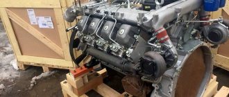
power line
Even from the designation it is clear that the engine is basically the same “740”, but slightly modernized. This V-shaped eight-cylinder turbodiesel 740.30-260 with an air intercooling system develops a power of 245 horsepower. But the engine is now paired with a completely new ZF Ecomid 9 S 1310 gearbox. This is the name of the new family of ZF gearboxes for medium-duty trucks, produced here at the ZF-Kama joint venture in Naberezhnye Chelny. This is a 9-speed gearbox for universal use, with a “creep” gear.
New ZF Ecomid 9 S 1310 gearbox. Production established in Naberezhnye Chelny
Chassis
An all-wheel drive three-axle truck with a 6x6 wheel arrangement has a load capacity of 11 tons. The load capacity of the rear bogie axles is 7900 kg. Base length – 3690+1320 mm. The torque distribution scheme from the engine is the most traditional. From the gearbox there is a driveshaft to the transfer case, from it there is a driveshaft to the front and rear axles, and a through middle axle. All around spring suspension. The vehicle being tested is equipped with an automatic tire pressure regulation system. Tires size 425/85R21, have a “J”, allowing movement at a speed of 100 km/h. Among other equipment, I noted the electric hydraulic lift of the cabin; apparently, the designers took pity on the driver because of the overall height of the chassis.
Short test drive
Painfully familiar and the same as before, a tight handle with a button opens the door, and after a moment I contemplate the interior of the cabin. I’ll say right away that the cabin is for the day, without a berth. The first impression is positive, but soon gives way to a very critical mood. Soft front panel, how many years could one have waited for it! But the plastic visor that goes around the quite good and quite informative instrument cluster is so rough that it has even managed to warp on a brand new car. In all other respects, it’s an interesting symbiosis of Kamaz’s with an injection of innovation.
The steering column still does not want to conveniently adjust to the driver, but the “trap” for the right foot has disappeared - a new suspended accelerator pedal has appeared. The “guitar” of the steering column switches of early KamAZ vehicles has long been forgotten, but a lever for switching and resetting the data area of the on-board computer has now been added on the left side. In the very left corner of the torpedo there is the usual electromagnetic ground switch.
Workplace in an updated cabin.
The strength frame of the cabin, despite the new optics and bumpers, remained the same: the glazing, by modern standards, is more reminiscent of the loopholes of an army armored car, but there are finally three windshield wipers - now they cover the entire width of the windshield cleaning area. I turn the ignition key and, my goodness, the instrument panel gives a short self-test, and the speedometer and tachometer needles make an honorable turn, like on decent cars!
Then everything is again Kamaz-style. True, in fairness, I note that noise and vibration insulation have become better. Yes, but where is the divider flag on the gearbox lever? Let's delve into the gear shift diagram taped nearby. Ah, that's it! This is a 9-speed ZF, and it has two fields of operation of 4 strokes + “creeping gear”. Changing ranges is done with a “slap in the face”. Let's try to get going. Compared to the very light clutch and gas pedals, the lever moves quite stiffly and requires getting used to. But this is nothing, especially for those who are not new to driving Soviet and Russian trucks. It is naive to expect directional stability from such “bast shoes” in combination with a high center of mass: the steering wheel constantly requires attention and trajectory correction, sometimes the amplitude of the steering wheel seems obscenely large, but do not forget that this is an SUV! And a real one, with honest locks and a lower gear in the transfer case.
On the right in the photo, on the steering column switch, there is control of the on-board computer. Tachograph is now essential equipment
I remembered the tire speed index - no, I don’t want to drive here at 100 km/h, comfortable and cruising - 60 - 70, no more. The springs all around do not contribute to ride comfort either. And the fuel consumption of all-wheel drive in this mode is quite adequate - 32.4 liters per hundred kilometers, according to the on-board computer. Surprisingly, in combination with its superstructure - a tanker, the car is perceived harmoniously. A rough worker who is not afraid of bad, broken roads and even off-road conditions, repairable, relatively simple and slightly modernized. Just don’t have to live in the cabin and drive a thousand kilometers every day. And for work on the ground - it’s really nothing, especially if you compare the price tag with foreign competitors...
The instrument panel is informative, although it looks overloaded. Below is the control of the off-road arsenal.
fuel tanker
As I already promised, a few words about the superstructure of the test car. An airfield tanker is far from just a “barrel”, but a very important superstructure. In addition to transporting fuel, the machine must ensure its filtration and accurate filling dosage. ATZ-11 of the Grabovsky Automobile Plant is a “suitcase-type” tank made of 09G2S sheet steel. The SVN-80 pump, with a capacity of 580 liters/min, is driven via a cardan shaft from the power take-off. The productivity of the fuel dispensing unit is 50 liters/min, the filtration fineness is 25 microns.
There are no frills under the hood. Even to add oil to the engine, the cabin will have to be raised. The new tail and optics have transformed the well-deserved cockpit.
Place on the market
The well-deserved age of the design did not become an obstacle to KamAZ-43118 confidently holding its niche in the market in the specific segment of medium-duty off-road trucks. The main trump card is the price. None of the foreign brands are ready to make a close offer. The plant's constant work on modernizing this car will allow this car to remain a sales leader for quite some time. The only thing that is extremely important for such machines is the operator’s understanding of why he is purchasing such equipment...
Perhaps this is a tribute to the transportation of dangerous goods, or perhaps modernization: the equipment behind the cabin is now in a reliable plastic casing, and the shape of the air intake is interesting. It is worth paying attention to the heated filter separator, mounted high and conveniently located.
Technical characteristics of KamAZ-43118
Daniil Minaev, photo by the author