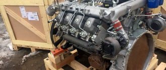
KAMAZ 43118 is a heavy-duty truck equipped with a complex mechanism for transmitting torque to the axles. Because these vehicles are designed for long trips on low-grade road surfaces and even off-road, they are equipped with several drive axles to increase cross-country ability, but this in turn complicates the rotation transmission system.
For proper distribution and coordination of torque in the required proportions between the front and rear axles and the engine, a transfer case is used. Our article will be about this important mechanism of the car and about how high-quality repairs of the KAMAZ 43118 transfer case are carried out.
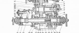
Transfer case KamAZ 43118 diagram
Transfer case weight 65111 43118 259.0 kg
Dimensions (Length x Width x Height) 0.687 x 0.547 x 0.661 m
Catalog number 65111-1800020-10
TRANSFER CASE DIAGRAM 4310
TRANSFER CASE DIAGRAM 43114
Transfer case Transfer case diagram 65111 43118 see above is installed on an all-wheel drive KamAZ, which can be operated in any road conditions - from highways to off-road.
Transfer case differential 65111
Transfer case 65111 43118 diagram
Its main purpose is to distribute the power from the power unit to the drive axles of the truck in a given proportion. The layout of the Razdatka 65111 provides for 2 KamAZ driving modes: driving on roads with normal road surfaces is carried out in the highest gear (second), on poor road surfaces or off-road - in the lowest (first).
Also, Transfer case 65111 has a differential lock for drive axles. It is used to avoid wheel slipping when driving in icy conditions.
Technical characteristics and diagram of transfer case 43118 65111
— device weight, kg – 257;
— gear ratios: low – 1.692; highest – 0.917;
— center differential (IOD): planetary type, with cylindrical wheels, asymmetrical, involves dividing power in the following shares: 66.7% - to the rear axles, 33.3% - to the front axle;
— control mechanism for gear shifting and MOD locking – remote, equipped with a pneumatic drive;
- lubrication of parts - in a combined way, carried out by spraying, as well as from a tray on the boat (low gear bearings).
Placement according to the transfer case diagram KAMAZ 65111 43118
Transfer case 65111 43118 is mounted behind the gearbox on the truck frame. The crankcase is equipped with protrusions (legs) on both sides, in which holes are provided for fasteners. The left mount consists of a suspension bracket attached to the frame, onto which 2 sets of suspension parts are attached. On the right, the same suspension and fastening parts are installed on a longitudinal beam, which rests on 2 brackets.
Technical description Transfer case KamAZ 65111 43118
Diagram and catalog KamAZ 65111 43118 transfer case consists of a crankcase and a cover with a vertical connector. It contains the assembled input and intermediate shafts, the front axle drive housing with speedometer drive components, the complete RK differential, and the MOD locking device; PTO winch drive with control mechanism; gear shift device; a blocking device that prevents two gears from engaging at once.
The crankcase and cover are cast from cast iron, machined and bolted together. There is a sealing gasket between the crankcase and the cover. After processing, one serial number is applied to them, which means only their joint use. De-staffing is not permitted.
Timely maintenance of the transfer case for the KamAZ 65111 43118 scheme will ensure uninterrupted operation of the device, as well as an adequate level of safety while driving. It includes the following activities:
— checking by visual inspection that there are no signs of oil leaking through the cuffs of the shafts (primary, axle drive);
— cleaning the valve located in the upper crankcase cover from dirt;
— checking the oil level in the transfer case by unscrewing the control plug on the right side of the crankcase. If insufficient oil is detected, the oil must be added;
- checking the transfer case fastenings - if they are loose, tighten the fastening elements;
— change the oil in the transfer case (once a year). The oil should be hot. To change it, turn out the filler and drain plugs. Next, clean the magnet of the drain plug of metal particles and adhering dirt. The transfer case housing is washed, the drain plug is put in place, engine oil is poured to the control hole, and the neutrals are turned for about 10 minutes. After this, drain the oil and fill in the main lubricant - also to the level of the control hole. Next, crank it in neutral for 5 minutes and, if necessary, add oil to the desired level.
Repair of the transfer case 65111 43118 with its removal from the vehicle and further disassembly should be carried out only when it is necessary to replace failed parts, or in the case of a high mileage of the truck for overhaul in the factory.
Before removing the transfer case, disconnect the propeller shafts, air supply hoses to gear shift devices, MOD locking devices, and PTO switch device; carry out unsealing and disconnection
Transfer case KamAZ 43118 65111 is one of the main parts of the vehicle. It is installed on the frame and secured to four rubber pads.
Its main functional purpose is the distribution and transmission of torque to the front axle of the machine and the rear axle of the trolley
KamAZ is undoubtedly a reliable truck that has been tested over more than one thousand kilometers of roads. By the time of its creation, the designers had developed and implemented the principle of a permanent drive with four cardan shafts.
11.12.2019 14:40
This is interesting: KamAZ 5320 gearbox - do-it-yourself adjustment and repair
four-wheel drive from the banks of the Kama
Review of the KamAZ 43118 truck (KAMAZ 43118)
Link to the original material and copyright holder - DALNOBOI.ORG
Remembering the all-wheel drive models of the Kama Automobile Plant, the old “warrior” KamAZ-4310 comes to mind. Today the car has been significantly modernized and bears the index 43118. We took the truck for a test drive.
A significant part of the vehicles leave the plant in Naberezhnye Chelny in the form of a chassis, in order to then try on a wide variety of superstructures, from dump trucks and mixers to complex airfield tankers, tow trucks and mobile workshops, or even research laboratories. I got a car with a “barrel” for testing - an airfield tanker. We will pay attention to its equipment a little later; now we will delve into the study of the chassis, which, on the one hand, is familiar, but also seriously updated.
power line
Even from the designation it is clear that the engine is basically the same “740”, but slightly modernized. This V-shaped eight-cylinder turbodiesel 740.30-260 with an air intercooling system develops a power of 245 horsepower. But the engine is now paired with a completely new ZF Ecomid 9 S 1310 gearbox. This is the name of the new family of ZF gearboxes for medium-duty trucks, produced here at the ZF-Kama joint venture in Naberezhnye Chelny. This is a 9-speed gearbox for universal use, with a “creep” gear.
New ZF Ecomid 9 S 1310 gearbox. Production established in Naberezhnye Chelny
Chassis
An all-wheel drive three-axle truck with a 6x6 wheel arrangement has a load capacity of 11 tons. The load capacity of the rear bogie axles is 7900 kg. Base length – 3690+1320 mm. The torque distribution scheme from the engine is the most traditional. From the gearbox there is a driveshaft to the transfer case, from it there is a driveshaft to the front and rear axles, and a through middle axle. All around spring suspension. The vehicle being tested is equipped with an automatic tire pressure regulation system. Tires size 425/85R21, have a “J”, allowing movement at a speed of 100 km/h. Among other equipment, I noted the electric hydraulic lift of the cabin; apparently, the designers took pity on the driver because of the overall height of the chassis.
Short test drive
Painfully familiar and the same as before, a tight handle with a button opens the door, and after a moment I contemplate the interior of the cabin. I’ll say right away that the cabin is for the day, without a berth. The first impression is positive, but soon gives way to a very critical mood. Soft front panel, how many years could one have waited for it! But the plastic visor that goes around the quite good and quite informative instrument cluster is so rough that it has even managed to warp on a brand new car. In all other respects, it’s an interesting symbiosis of Kamaz’s with an injection of innovation.
The steering column still does not want to conveniently adjust to the driver, but the “trap” for the right foot has disappeared - a new suspended accelerator pedal has appeared. The “guitar” of the steering column switches of early KamAZ vehicles has long been forgotten, but a lever for switching and resetting the data area of the on-board computer has now been added on the left side. In the very left corner of the torpedo there is the usual electromagnetic ground switch.
Workplace in an updated cabin.
The strength frame of the cabin, despite the new optics and bumpers, remained the same: the glazing, by modern standards, is more reminiscent of the loopholes of an army armored car, but there are finally three windshield wipers - now they cover the entire width of the windshield cleaning area. I turn the ignition key and, my goodness, the instrument panel gives a short self-test, and the speedometer and tachometer needles make an honorable turn, like on decent cars!
Then everything is again Kamaz-style. True, in fairness, I note that noise and vibration insulation have become better. Yes, but where is the divider flag on the gearbox lever? Let's delve into the gear shift diagram taped nearby. Ah, that's it! This is a 9-speed ZF, and it has two fields of operation of 4 strokes + “creeping gear”. Changing ranges is done with a “slap in the face”. Let's try to get going. Compared to the very light clutch and gas pedals, the lever moves quite stiffly and requires getting used to. But this is nothing, especially for those who are not new to driving Soviet and Russian trucks. It is naive to expect directional stability from such “bast shoes” in combination with a high center of mass: the steering wheel constantly requires attention and trajectory correction, sometimes the amplitude of the steering wheel seems obscenely large, but do not forget that this is an SUV! And a real one, with honest locks and a lower gear in the transfer case.
On the right in the photo, on the steering column switch, there is control of the on-board computer. Tachograph is now essential equipment
I remembered the tire speed index - no, I don’t want to drive here at 100 km/h, comfortable and cruising - 60 - 70, no more. The springs all around do not contribute to ride comfort either. And the fuel consumption of all-wheel drive in this mode is quite adequate - 32.4 liters per hundred kilometers, according to the on-board computer. Surprisingly, in combination with its superstructure - a tanker, the car is perceived harmoniously. A rough worker who is not afraid of bad, broken roads and even off-road conditions, repairable, relatively simple and slightly modernized. Just don’t have to live in the cabin and drive a thousand kilometers every day. And for work on the ground - it’s really nothing, especially if you compare the price tag with foreign competitors...
The instrument panel is informative, although it looks overloaded. Below is the control of the off-road arsenal.
fuel tanker
As I already promised, a few words about the superstructure of the test car. An airfield tanker is far from just a “barrel”, but a very important superstructure. In addition to transporting fuel, the machine must ensure its filtration and accurate filling dosage. ATZ-11 of the Grabovsky Automobile Plant is a “suitcase-type” tank made of 09G2S sheet steel. The SVN-80 pump, with a capacity of 580 liters/min, is driven via a cardan shaft from the power take-off. The productivity of the fuel dispensing unit is 50 liters/min, the filtration fineness is 25 microns.
There are no frills under the hood. Even to add oil to the engine, the cabin will have to be raised. The new tail and optics have transformed the well-deserved cockpit.
Place on the market
The well-deserved age of the design did not become an obstacle to KamAZ-43118 confidently holding its niche in the market in the specific segment of medium-duty off-road trucks. The main trump card is the price. None of the foreign brands are ready to make a close offer. The plant's constant work on modernizing this car will allow this car to remain a sales leader for quite some time. The only thing that is extremely important for such machines is the operator’s understanding of why he is purchasing such equipment...
Perhaps this is a tribute to the transportation of dangerous goods, or perhaps modernization: the equipment behind the cabin is now in a reliable plastic casing, and the shape of the air intake is interesting. It is worth paying attention to the heated filter separator, mounted high and conveniently located.
Technical characteristics of KamAZ-43118
Daniil Minaev, photo by the author
driversdigest.ru
Internal details
Before talking about the step-by-step repair of the KAMAZ 43118 transfer case (the diagram of the device itself is below), let's take a closer look at this element. The KAMAZ 43118 design has a transfer case with a two-stage design, which is equipped with a special electro-pneumatic lock. In addition, the composition includes the following spare parts:
- Drive shaft and axle drive shafts.
- Gear transmissions, as well as reduction gears.
- Center differential.
- The body (also called the crankcase) is cast from metal and filled with a lubricant.
The transfer case itself is installed in the truck behind the gearbox; on the one hand, it is located on the side member of the vehicle frame, and on the other, on a beam located between the cross members. The blocking process occurs thanks to a pneumatic system; its control drive is located directly in the KAMAZ 43118 cab. The three-way control valve is divided into three positions:
- Neutral.
- First transfer.
- Second gear.
The metal case has an installation hatch for installing the power take-off; oil is poured into it through a special hole, which is then tightly closed with a plug. The winch mechanism is installed on the splines of the output shaft.
four-wheel drive from the banks of the Kama
KamAZ-43118: four-wheel drive from the banks of the Kama
20.04.2015
4 199
A significant part of the vehicles leave the plant in Naberezhnye Chelny in the form of a chassis, in order to then try on a wide variety of superstructures, from dump trucks and mixers to complex airfield tankers, tow trucks and mobile workshops, or even research laboratories. I got a car with a “barrel” for testing - an airfield tanker. We will pay attention to its equipment a little later; now we will delve into the study of the chassis, which, on the one hand, is familiar, but also seriously updated.
power line
Even from the designation it is clear that the engine is basically the same “740”, but slightly modernized. This V-shaped eight-cylinder turbodiesel 740.30-260 with an air intercooling system develops a power of 245 horsepower. But the engine is now paired with a completely new ZF Ecomid 9 S 1310 gearbox. This is the name of the new family of ZF gearboxes for medium-duty trucks, produced here at the ZF-Kama joint venture in Naberezhnye Chelny. This is a 9-speed gearbox for universal use, with a “creep” gear.
New ZF Ecomid 9 S 1310 gearbox. Production established in Naberezhnye Chelny
Chassis
An all-wheel drive three-axle truck with a 6x6 wheel arrangement has a load capacity of 11 tons. The load capacity of the rear bogie axles is 7900 kg. Base length – 3690+1320 mm. The torque distribution scheme from the engine is the most traditional. From the gearbox there is a driveshaft to the transfer case, from it there is a driveshaft to the front and rear axles, and a through middle axle. All around spring suspension. The vehicle being tested is equipped with an automatic tire pressure regulation system. Tires size 425/85R21, have a “J”, allowing movement at a speed of 100 km/h. Among other equipment, I noted the electric hydraulic lift of the cabin; apparently, the designers took pity on the driver because of the overall height of the chassis.
Short test drive
Painfully familiar and the same as before, a tight handle with a button opens the door, and after a moment I contemplate the interior of the cabin. I’ll say right away that the cabin is for the day, without a berth. The first impression is positive, but soon gives way to a very critical mood. Soft front panel, how many years could one have waited for it! But the plastic visor that goes around the quite good and quite informative instrument cluster is so rough that it has even managed to warp on a brand new car. In all other respects, it’s an interesting symbiosis of Kamaz’s with an injection of innovation.
The steering column still does not want to conveniently adjust to the driver, but the “trap” for the right foot has disappeared - a new suspended accelerator pedal has appeared. The “guitar” of the steering column switches of early KamAZ vehicles has long been forgotten, but a lever for switching and resetting the data area of the on-board computer has now been added on the left side. In the very left corner of the torpedo there is the usual electromagnetic ground switch.
Workplace in an updated cabin.
The strength frame of the cabin, despite the new optics and bumpers, remained the same: the glazing, by modern standards, is more reminiscent of the loopholes of an army armored car, but there are finally three windshield wipers - now they cover the entire width of the windshield cleaning area. I turn the ignition key and, my goodness, the instrument panel gives a short self-test, and the speedometer and tachometer needles make an honorable turn, like on decent cars!
Then everything is again Kamaz-style. True, in fairness, I note that noise and vibration insulation have become better. Yes, but where is the divider flag on the gearbox lever? Let's delve into the gear shift diagram taped nearby. Ah, that's it! This is a 9-speed ZF, and it has two fields of operation of 4 strokes + “creeping gear”. Changing ranges is done with a “slap in the face”. Let's try to get going. Compared to the very light clutch and gas pedals, the lever moves quite stiffly and requires getting used to. But this is nothing, especially for those who are not new to driving Soviet and Russian trucks. It is naive to expect directional stability from such “bast shoes” in combination with a high center of mass: the steering wheel constantly requires attention and trajectory correction, sometimes the amplitude of the steering wheel seems obscenely large, but do not forget that this is an SUV! And a real one, with honest locks and a lower gear in the transfer case.
On the right in the photo, on the steering column switch, there is control of the on-board computer. Tachograph is now essential equipment
I remembered the tire speed index - no, I don’t want to drive here at 100 km/h, comfortable and cruising - 60 - 70, no more. The springs all around do not contribute to ride comfort either. And the fuel consumption of all-wheel drive in this mode is quite adequate - 32.4 liters per hundred kilometers, according to the on-board computer. Surprisingly, in combination with its superstructure - a tanker, the car is perceived harmoniously. A rough worker who is not afraid of bad, broken roads and even off-road conditions, repairable, relatively simple and slightly modernized. Just don’t have to live in the cabin and drive a thousand kilometers every day. And for work on the ground - it’s really nothing, especially if you compare the price tag with foreign competitors...
The instrument panel is informative, although it looks overloaded. Below is the control of the off-road arsenal.
fuel tanker
As I already promised, a few words about the superstructure of the test car. An airfield tanker is far from just a “barrel”, but a very important superstructure. In addition to transporting fuel, the machine must ensure its filtration and accurate filling dosage. ATZ-11 of the Grabovsky Automobile Plant is a “suitcase-type” tank made of 09G2S sheet steel. The SVN-80 pump, with a capacity of 580 liters/min, is driven via a cardan shaft from the power take-off. The productivity of the fuel dispensing unit is 50 liters/min, the filtration fineness is 25 microns.
There are no frills under the hood. Even to add oil to the engine, the cabin will have to be raised. The new tail and optics have transformed the well-deserved cockpit.
Place on the market
The well-deserved age of the design did not become an obstacle to KamAZ-43118 confidently holding its niche in the market in the specific segment of medium-duty off-road trucks. The main trump card is the price. None of the foreign brands are ready to make a close offer. The plant's constant work on modernizing this car will allow this car to remain a sales leader for quite some time. The only thing that is extremely important for such machines is the operator’s understanding of why he is purchasing such equipment...
Perhaps this is a tribute to the transportation of dangerous goods, or perhaps modernization: the equipment behind the cabin is now in a reliable plastic casing, and the shape of the air intake is interesting. It is worth paying attention to the heated filter separator, mounted high and conveniently located.
Technical characteristics of KamAZ-43118
Daniil Minaev, photo by the author
dalnoboi.org
First symptoms of problems
In order to understand whether the KAMAZ 43118 transfer case needs repair, it is important to monitor the following signs:
- Constantly or periodically, knocks, noises and other sounds occur while driving, which warn of problems in normal operating mode.
- The transmissions began to turn off on their own. This is the result of wear and tear on parts such as the clutch, gears, and shift forks.
- Difficulties arose in changing gears - it “sticks”, does not work, “sticks”.
- The housing or fastening elements have been subjected to mechanical stress.
All of the above negative phenomena occur in various modifications of trucks. If you notice one or several symptoms at once, then an urgent repair appointment for the KAMAZ 43118 transfer case is required. The device may soon completely fail and put your life in danger!
Onboard KAMAZ 43118 (4X4 all-wheel drive) with CMU
KAMAZ is always famous for its excellent cross-country ability, and even more so for its all-wheel drive chassis 43118 with a 4x4 wheel arrangement. To improve cross-country ability, the car is equipped with a tire pressure monitoring system, so it can travel not only on bad roads, but also on virtually no roads.
Of the variety of vehicles intended for cargo transportation, we can especially highlight the KAMAZ with a manipulator crane, which is not only capable of independently performing loading and unloading operations, but also delivering cargo along any roads.
KAMAZ with a crane installation is a truck with an onboard platform about 5.5 meters long, which is ready to carry up to 9 tons of various cargo. If you need to change semi-trailers, then you can buy a KAMAZ with a manipulator, equipped with a fifth wheel coupling.
As for crane-manipulator installations, the vehicle can be equipped with both a hydraulic crane and a crane with a cable system. The first type is more universal; it can use replaceable working parts: grabs, hydraulic drills. For example, the hydraulic CMU Fassi F195 with a reach of 4 m can lift 4 tons of cargo, and with the largest reach of eight meters it can handle a two-ton weight.
The second, cable type, has a larger boom reach and allows you to move the load strictly vertically, and pick it up and lower it below the surface of the earth. The crane manipulator unic KAMAZ 43118 with a three-meter reach will lift a load of 6 tons, and with a reach of 19 meters it will lift only 350 kg.
At SpetsTechKomplekt LLC you can buy KAMAZ 43118 with cranes from the following manufacturers: EFFER PM, AMCO, VEBA, PALFINGER, HIAB, BONFIGLIOLI, FASSI, FERRARI.
TECHNICAL CHARACTERISTICS Technical characteristics of KMU Load capacity at maximum reach, kg 1130 Maximum reach, m 7.74 Load moment, t*m 9.60 g Technical characteristics of the vehicle Base chassis KAMAZ-43118 Overall dimensions of the vehicle, mm: - length 8640 - width 2530 - height 3600 Vehicle base, mm 3690/1320Wheel vehicle formula 6x6 Curb weight, kg 11400 Gross vehicle weight, kg 20900 - on the front axle 5600 - on the rear axle 15300 Weight of transported cargo, kg 9350 Internal dimensions of the platform, mm: - length 5100 - width 2470 - height 580 Loading height of the platform, mm 1600
spectexkomplekt.ru
Warning light circuit diagram
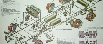
This system controls the rear brakes and turn signals. It serves to notify other road users about the maneuvers the truck is making. The general diagram of this system is shown in the figure below:
The numbers on the diagram indicate:
- left lamp;
- right lamp;
- turn signal and hazard warning relay;
- fuse PR 119 (6 A);
- light switch;
- fuse 13.3722 (7.5 A);
- fuse PR 310 (10 A);
- hazard warning light switch;
- turn signal right
- left turn indicator;
- rear left lamp
- rear right lamp;
- brake light switch;
- trailer solenoid valve switch;
- brake signal relay;
- sound signal (buzzer);
- 18, 19 — switches for pressure drop alarms in the brake air drive receivers;
- parking brake warning switch;
- relay-interrupter for the parking brake system activation indicator;
- reverse light switch;
- reversing light;
- trailer socket 24 V;
- center differential lock warning switch;
- 27, 28 — signaling units;
- oil filter clogged warning switch;
I. to the instrument and starter switch;
II. to the coolant temperature gauge;
III. to the tachometer;
IV. to the speedometer.
This scheme includes the following subsystems:
- Hazard warning system;
- Brake (stop) indicators;
- Direction indicators
- Indicator lamps for turning on the direction indicators of the vehicle and trailer;
- Center differential lock indicator lamps,
- Parking brake system;
- Drops in air pressure in the pneumatic drive circuits of brake mechanisms;
- Warning lamp blocks,
In addition, the system includes a variety of switches and relays.
Brief explanations of the diagram. Under the number 8 hides the well-known “emergency warning light”. That is, this switch turns on all the direction indicators at once.
The turn signals themselves, in normal mode, are turned on by a combination light switch, marked in the diagram with the number 5. Their intermittent lighting is provided by a special relay (3).
The driver observes the operation of the direction indicators thanks to the signal lamps (26), while the vehicle and the trailer have different signal lamps.
The braking signal to the feet comes from a pneumoelectric sensor (13). The signal from it goes through the intermediate relay (15), and then to the stop lamps. I draw your attention to the fact that the stop circuit is connected via an ammeter, and is not connected by the instrument switch and starter. This is done so that the stop lights light up even when the ignition is turned off.
You need to know that the brake alarm turns on even when the parking brake is applied - the handbrake. The sensor marked on the diagram with the number 20 is responsible for turning on the stops when the handbrake is turned on. When the parking brake is applied, the stops light up intermittently. This operation is ensured by a relay-interrupter (21).
How is the ZIL 131 bridge blocked?
The diaphragm moves the rod 6 with the fork 10 and the locking clutch 11. As a result, the engagement clutch 11 is connected by the end teeth to the teeth of the locking clutch 13, and the right axle shaft with the differential cup is blocked.
Interesting materials:
How long does it take to make an electronic signature? How long does it take for a parcel to arrive from Sharapovo? How long does watermelon last? How long does it take to treat gonorrhea in men? How long does it take for chestnut to germinate? How long does it take for begonia tubers to germinate? How long does it take for acorns to germinate? How long does it take for geraniums to grow from seeds? How long does Poinsettia bloom? How long do marigolds bloom?
Causes of breakdowns
- Gear teeth are broken.
- The bearings are worn out and need to be replaced with new ones long ago.
- Burrs have formed on the splines.
- The sliders bent.
- The seal of the diaphragms of the pneumatic chambers is damaged.
- The installation strength of the couplings has weakened.
Errors and damage to parts can only be detected during operation of the truck, because during maintenance and repair, a visual inspection can only minimally assess the size of the damage. The technician will detect the problem if he notices cracks and weak fasteners, but the main “foci of disease” appear only during the direct functioning of the entire mechanism. Therefore, it is important to monitor the “behavior” of KAMAZ on the road.
This is interesting: GAZ-53 engine: technical characteristics and design
Signs of malfunctioning mechanisms
Repair of the KAMAZ transfer case is necessary if the following faults are detected:
How to prevent KamAZ transfer case malfunction
- Extraneous noises, knocking, and other sounds indicating a violation of the normal operating mode.
- Spontaneous gear disengagement, which occurs due to wear of gears, couplings, and shift forks.
- Difficulty in shifting gears, jamming, failure of the locking mechanism.
- Mechanical damage to the housing or fastening elements.
The listed malfunctions are typical for all types of transfer cases of KAMAZ vehicles. The main causes of malfunctions are:
- Broken gear teeth.
- Bearing wear.
- Violation of the tightness of the diaphragms of pneumatic chambers.
- The appearance of burrs on the splines, bent sliders.
- Wear of connections, in particular - violation of the strength of coupling installation.
Most often, malfunctions manifest themselves during operation; somewhat less often they are detected during routine or repair work or vehicle maintenance. A visual inspection can only detect cracks or loosening of fasteners; all internal defects appear during the direct operation of the mechanism.
Warning light circuit diagram
This system controls the rear brakes and turn signals. It serves to notify other road users about the maneuvers the truck is making. The general diagram of this system is shown in the figure below:
The numbers on the diagram indicate:
- left lamp;
- right lamp;
- turn signal and hazard warning relay;
- fuse PR 119 (6 A);
- light switch;
- fuse 13.3722 (7.5 A);
- fuse PR 310 (10 A);
- hazard warning light switch;
- turn signal right
- left turn indicator;
- rear left lamp
- rear right lamp;
- brake light switch;
- trailer solenoid valve switch;
- brake signal relay;
- sound signal (buzzer);
- 18, 19 — switches for pressure drop alarms in the brake air drive receivers;
- parking brake warning switch;
- relay-interrupter for the parking brake system activation indicator;
- reverse light switch;
- reversing light;
- trailer socket 24 V;
- center differential lock warning switch;
- 27, 28 — signaling units;
- oil filter clogged warning switch;
I. to the instrument and starter switch;
II. to the coolant temperature gauge;
III. to the tachometer;
IV. to the speedometer.
This scheme includes the following subsystems:
- Hazard warning system;
- Brake (stop) indicators;
- Direction indicators
- Indicator lamps for turning on the direction indicators of the vehicle and trailer;
- Center differential lock indicator lamps,
- Parking brake system;
- Drops in air pressure in the pneumatic drive circuits of brake mechanisms;
- Warning lamp blocks,
In addition, the system includes a variety of switches and relays.
Brief explanations of the diagram. Under the number 8 hides the well-known “emergency warning light”. That is, this switch turns on all the direction indicators at once.
The turn signals themselves, in normal mode, are turned on by a combination light switch, marked in the diagram with the number 5. Their intermittent lighting is provided by a special relay (3).
The driver observes the operation of the direction indicators thanks to the signal lamps (26), while the vehicle and the trailer have different signal lamps.
The braking signal to the feet comes from a pneumoelectric sensor (13). The signal from it goes through the intermediate relay (15), and then to the stop lamps. I draw your attention to the fact that the stop circuit is connected via an ammeter, and is not connected by the instrument switch and starter. This is done so that the stop lights light up even when the ignition is turned off.
You need to know that the brake alarm turns on even when the parking brake is applied - the handbrake. The sensor marked on the diagram with the number 20 is responsible for turning on the stops when the handbrake is turned on. When the parking brake is applied, the stops light up intermittently. This operation is ensured by a relay-interrupter (21).
Repair process
- The device itself is removed.
- The drain plug is unscrewed and the oil is poured out.
- The shields are dismantled on the platform floor.
- The main driveshaft is disconnected.
- The drive shafts of the intermediate and front axles are separated.
- The lighting and ground wires and the speedometer are turned off.
- The pneumatic hoses are disconnected.
- The transfer case is attached to the lift cables using special eyes.
- Unscrew four self-locking nuts.
- Using a lift, the transfer case is quietly lowered onto a special trolley for transportation to the repair site.
- Malfunctions are repaired, failed elements are replaced with new similar parts, crooked sliders are leveled, burrs are ground, the entire set of moving parts is adjusted and adjusted.
The stages of this work are strictly regulated by instructions, safety standards and technical requirements.
Principle of operation
Activation of the switches blocks the access of compressed air to the pneumatic chambers, as a result of which the diaphragms take the required position. The motor power is distributed to the holders and satellites. When driving on a good dirt road, the satellites carry the gears of the mechanism with them and work as a single unit. When uneven road surfaces (off-road) appear, the functionality of the satellites changes; they begin to rotate around their axis and around the main axis. This consequence is associated with the difference in the travel of the bogie and the front axle and the appearance of differences in the rotation speed of the epicycle with the sun gear. To prevent both gears from being engaged, the design provides a lock that eliminates this possibility.
The differential is activated using a pneumatic chamber, and the clutch moves between the front axle drive system and the holder. The coupling is the connecting link between the presented parts. The resulting loads and forces are distributed between the bogie and the front axle. Distribution occurs proportionally according to the calculated scheme.
When the differential is unlocked, the load on the gearbox is completely eliminated. Thus, the service life of the mechanism is extended. The switched-on state of this device is required only under conditions of extreme loads (ice, mud, sand), when there is a threat to safe driving.
Lubrication of RK 65111 is carried out as follows: a certain amount of oil is sprayed, after which 5 liters are poured into the crankcase.
Components of the mechanism
In KAMAZ 43118, the gearbox has a two-stage design and is equipped with an electro-pneumatic lock.
The KAMAZ transfer case structure includes the following elements:
- Drive shaft.
- Center differential with lock.
- Drive shafts of front and rear axles.
- Gear transmissions.
- Downshift.
- Cast metal housing (crankcase) filled with lubricant.
KamAZ 43118 transfer case diagram
The KAMAZ 43118 transfer case is installed behind the gearbox, one side on the side member of the vehicle frame and the other side on a beam located between the cross members.
The differential is locked using a pneumatic system, the control drive of which is located in the driver's cabin.
The three-way control valve has three positions - neutral, first and second gear. The crankcase has an installation hatch in the upper part through which the power take-off is installed.
Oil is filled through a special hole, normally closed with a plug. A winch is attached to the output shaft splines.
Basic principles of operation of the transfer case in a KAMAZ vehicle
The KAMAZ 43118 transfer case transfers power to the drive shaft of rotational motion and transfers power to the distribution box in which the center differential (MO) is installed. There are three types of MO:
- Friction clutch.
- Viscous coupling (viscous coupling).
- Self-locking differential Torsen model. Structurally, it is a worm gear; torque is transmitted due to friction.
Friction clutch in KAMAZ 43118. It is a set of disks, the adhesion density of which to each other is determined by the rotation conditions. Slipping of any axle causes the discs to compress and the clutch to lock, as a result of which the axle with the greatest degree of traction receives power.
Viscous coupling in KAMAZ 43118. A set of perforated discs placed in a silicone mass. Half of them are connected to the body, the other to the hub. Slipping of one of the axles causes locking and binds the hub and clutch housing.
Of all types of MO, the viscous coupling is the most popular; it is simple and reliable in operation.
Transfer case KAMAZ-4310,43118
Box device. The main components are the following:
- Carter;
- Main or drive shaft;
- Intermediate or secondary shaft;
- Shaft located on the front axle;
- Shaft for driving axles at the rear of the car;
- Shaft intended for power take-off;
- Center differential;
- Central control drive;
- The gear is responsible for overdrive.
Transfer case KamAZ 4310
The KAMAZ 4310, 43118 is equipped with a transfer case, usually two-stage, the differential on it is usually lockable and has an electro-pneumatic drive. In first gear the number is set to 1.692, in second – 0.917. The fastening of the box is usual, on rubber pads and brackets and is fixed on the frame spar, as well as on the cross members located between the two.
The crankcase on the KAMAZ 4310.43118 motor vehicle is made as a cast structure on which a vertical connector is located. A power take-off box is installed on the upper section of the crankcase using a hatch. This is the structure of the box.
The crankcase is closed with a lid; the manufacturer provides for oil filling through this connector, which is closed with a plug. The driver can easily check the level of consumed oil; this can be done through the lower hole, which is also equipped with a magnetic plug. The crankcase is protected on top by a lid, that is, the crankcase hatch, and it is intended for power take-off.
The operation of the drive shaft involves two types of bearings: ball bearings (1 piece) and cylindrical roller bearings (2 pieces). The bearings located in front have a seal, and the rear bearing is located inside the crankcase, in a special compartment.
There is a gear on the shaft; it is not only a drive gear, but it is also pressed in, and the gear responsible for power take-off is already welded onto the hub.
The intermediate shaft moves thanks to bearings, both roller and cylindrical, which are protected by covers. The intermediate gear, as well as the first gear, are fixed to the shaft and move differently on it. From the oil sump, which is located above the intermediate shaft, oil flows onto the gear rollers by gravity. Both gears have teeth embedded in them, and it is on them that the clutch is attached, which is responsible for the first gear, and specifically for engaging it.
How does a center differential work? As you know, the wheels of the front axle and the wheels on the trolley spin differently, especially if the movement occurs on an unpaved road, on a country road, or equipped only with crushed stone backing. The differential distributes the torque between them in a percentage ratio of 1:2; it is installed at the very bottom of the crankcase on two bearings: roller and cylindrical. Also provided:
- Main, drive gear;
- Rear clip, and front;
- Solar, as well as in a pair of epicyclic gears;
- Satellites.
Both cages are fixed on the drive gear, while the sun gear is located on the splines of the front axle shaft, and the epicyclic gear is paired with the bogie shaft. The satellites are mounted on bushings made of bronze, in the front differential race and support washer. Their task is to always be in conjunction with the gears, as mentioned above with the solar and epicyclic ones.
On the holder in front there are two roller bearings, and the gear responsible for second gear also rotates there. A gear coupling helps connect to the front cage. The coupling allows you to lock the differential, and on the front shaft of the axle drive there is a gear to drive the sensor, which reflects the readings of the speedometer, which is located on the crankcase.
Using the switch, which is located in the driver's cabin, you can control the gearbox (RK), the system is responsible for this action, which includes a switch, electric pneumatic valves, two pneumatic chambers and pneumatic actuators, and a sensor responsible for switching on.
Device
Moscow designers also took part in the creation of the KamAZ car. At the time of the creation of the car, an advanced principle for the interaction of drive axles was developed and implemented. This refers to a permanent drive, which has four cardan shafts.
At the same time, the transmission is equipped with a center differential, which is supported by electric and pneumatic locking. There are several modifications that have some differences, but they are not significant. The KAMAZ 4310, 43118 vehicle is equipped with a KAMAZ-740.10 engine, which has a power of 210 -220 hp.
The basic version of the KamAZ 4310 vehicle is characterized by a shorter platform with a voluminous awning and a tailgate that folds down. The body has a row of seats for 30 people, which can be transformed, that is, they are folding. Years of production: 1983-1990.
How to reassemble
The assembly process is carried out in the reverse order of the dismantling described above:
- The transfer case returns to the installation area and is raised by the lift to its previous height.
- Align the holes of the RC and the supporting structure to screw the bolts and nuts back into place.
- Pneumatic hoses are attached.
- The ground wire and control lighting wires are connected.
- Speedometer plug, driveshafts are attached.
Please note that when installing cardan shafts, it is necessary to tighten the self-locking nuts to the required torque values according to the instructions; for this you need to use special torque wrenches. When the transfer case is installed, oil is poured back into the housing through the hole. The oil level must correspond to the position of the lower control plug.
_______________________________________________________________________________
Adding oil to the crankcase
TSp-15k
New fuel is added to the crankcase through a special connector closed with a plug. It is possible to control the oil level through the lower hole, supplemented by a magnetic plug. Typically, about 5 liters of fluid are required in the crankcase. It is recommended to use TSp-15k oil.
If there is not enough fuel in the box, it may be difficult to change gears.
Removing the RC from KamAZ-4310
To independently repair the RK, you need to know the structure of this unit. To remove it, it is advisable to drain the liquid in it. Especially for this you need to unscrew the drain plug (you need to substitute an empty container in advance). Next, you should remove the platform floor panels, disconnect the driveshaft, and then proceed to disconnect the plug connection of the speedometer, warning lamps, and pneumatic chamber hoses. Finally, you need to unscrew the nuts and bolts on the valve, after which you should remove the unit.
Thus, KamAZ-4310 is a truck that is equipped with reliable working mechanisms designed for a long working life. The machine is equipped with a transfer case (2 stages) as standard. Also, it should be highlighted the presence of an asymmetrical center differential, complemented by an electro-pneumatic gear shift control drive. The control panel is located on the frame. This box is ready to provide maximum cross-country ability on the roads.