Tractor transmission elements and their purpose
One of the most important elements of every tractor is its transmission. The ability of the tractor to do its job directly depends on its reliability and serviceability.
In cases where the design of a tractor transmission includes only one mechanism with gears, it is called a mechanical transmission. If, in addition to the above elements, the design includes a torque converter, then such a design will be called hydromechanical.
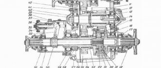
The letters in the image indicate diagrams of mechanical wheeled and tracked transmissions.
The following elements are indicated by numbers:
- 1 – final drive;
- 2 – transmission differential;
- 3 – clutch device;
- 4 – gearbox;
- 5 – main gear;
- 6 – intermediate connection;
- 7 – mechanisms responsible for turning;
- 8 and 9 – special elements;
- 10 – cardan shafts.
Due to the relatively simple design and reliability during operation, mechanical transmissions are installed on most tractors. Their design includes the following elements:
- Clutch is a device designed to transmit torque from the engine to the wheels of the tractor. This element also allows you to temporarily disconnect the motor from other devices and smoothly connect it again;
- The intermediate connection plays the role of a device that transmits rotation from the shaft to other elements of the transmission. Thanks to the presence of this part, the tractor continues to operate even in cases of incorrect position of the shaft axes resulting from incorrect assembly of the unit;
- Gearbox - used to convert torque in direction and magnitude. In other words, the gearbox makes it possible to change the gear ratio, thus changing the speed of movement. In addition, the gearbox makes it possible to change the trajectory of the tractor and perform a smooth turn of the equipment;
- The main gear is responsible for reducing the shaft speed and increasing torque;
- Differential is a device that distributes torque between shafts and wheels. Thanks to this element, the wheels of the car are able to rotate at different frequencies;
- Final drives are designed to reduce the rotation speed and increase the torque transmitted by the motor;
- The turning mechanism gives the tractor the ability to turn;
- Special elements are creepers or transfer cases. They are not always installed on equipment;
- Driveshafts transmit torque between misaligned transmission elements.
A fairly simple mechanical transmission scheme is popular due to its simplicity and the possibility of quick repairs. If necessary, almost every driver will be able to identify and repair the breakdown of this unit.
Lecture on MDK "Transmission"
Purpose and classification of transmissions of tractors and cars. TransmissionTractors (cars) are united by units and mechanisms that transmit engine torque to the drive wheels and change the torque and rotation speed in magnitude and direction. In tractors, in addition, the transmission can transmit part of the engine power to a machine that is aggregated with the tractor.
Transmission is necessary for the following reasons:
— there is a difference in the rotation speed of the engine and propulsion shafts;
— there is a change in the resistance to movement of the machine, depending on operating conditions, over a wide range
Internal combustion engines have limited self-regulating properties - automatically changing torque and speed depending on changes in external resistances. These reasons predetermine the installation of transmissions on tractors and cars.
The transmission serves to transmit engine torque to the drive wheels of the tractor (car), and is also used to transfer part of the engine power to the machine attached to the tractor.
Using the transmission, you can change the torque and rotation speed of the drive wheels in value and direction.
According to the method of changing torque, transmissions are divided into:
Stepped, stepless and combined.
A stepped transmission includes a clutch, intermediate connections (universal drives), gearbox, final drive, differential, and final drives.
transmits torque from the engine shaft to the drive wheels, and also drives various equipment mounted on the vehicle.
Transmission includes:
1) a permanently closed disc friction clutch (clutch), which serves to smoothly connect and quickly disconnect a running engine from the transmission;
2) a stepped gearbox, which is made in the form of a gear reducer with a variable gear ratio and is designed to change the amount of torque supplied to the drive wheels depending on driving conditions, ensure the vehicle moves in reverse and disconnect the running engine from the transmission during long stops of the car;
3) cardan shafts that transmit torque at a varying angle from the gearbox mounted on the frame to the sprung rear axle;
4) main gear (single or double), increasing the traction force on the drive wheels;
5) a differential, which serves to distribute torque between the drive wheels and ensures their rotation at different angular speeds when the car moves around corners and on uneven surfaces;
6) axle shafts (shafts) transmitting torque to the drive wheels attached to them; The final drive, differential and axle shafts enclosed in a casing are called the rear drive axle.
Normal cross-country vehicles, adapted for work on highways and dirt roads, have one drive axle—the rear one, while off-road vehicles have two (front and rear) or three (front and two rear) drive axles. The transmission of a car with two drive axles, in addition to the clutch, gearbox, propeller shaft 6 and rear drive axle, also includes a front drive axle with steered wheels and a transfer case connected to it and the gearbox by driveshafts.
In transmissions of normal and all-terrain vehicles used as a base for construction vehicles, provision is made for supplying part of the engine power to a transfer gearbox, which has a power take-off shaft for driving attachments. The transfer gearbox can drive the hydraulic pump of the attachment control system.
The chassis transmits the force of gravity of the car to the road and carries out its forward movement. It consists of a supporting frame on which all units, the body and the driver’s cabin are mounted, front and rear axles with pneumatic wheels and an elastic suspension connecting the supporting frame to the axles.
The wheels of normal cross-country vehicles are, as a rule, equipped with high-pressure pneumatic tires 5-7 kgf/cm2 (0.49-0.69 MPa), and all-terrain vehicles are equipped with low-pressure tires 1.75-5 kgf/cm2 (0.17 - 0.49 MPa) with an increased supporting surface.
The control mechanisms are combined into two independent systems: steering - to change the direction of movement of the car by turning the front steered wheels and brake - to reduce speed and quickly stop the car
Tractors are used in construction to move heavy loads on trailers on bad roads and rough terrain where a car cannot pass, as well as for the movement and operation of mounted or trailed construction machines.
There are pneumatic wheeled and tracked tractors, which are divided into several classes depending on the maximum tractive effort in tf (kN) on the tractor hook at rated engine power. Tractors used in construction and agriculture belong to the 0.2 traction class. 0.6. 0.9. 1.4 tf (13.8 kn), 3 tf (29.5 kn), 6 tf (59 kn), 9 tf (88 kn), 15 tf (149 kn), 25 tf (345 kn) and 35 tf (343 kn).
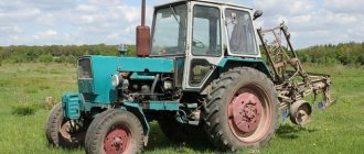
Pneumatic wheeled tractors have relatively high travel speeds (up to 40 km/h), high mobility and maneuverability; They are used as transport vehicles and as a base for installing various attachments (loading, crane, bulldozer and earthmoving), used in excavation and small-scale construction and installation work at dispersed sites. Pneumatic wheeled tractors are used most effectively on paved roads. Their main drawback is the relatively high specific pressure on the ground (0.2-0.4 MPa), which significantly reduces the vehicle's maneuverability.
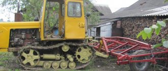
Crawler tractors have found wider application in construction due to the significant traction force on the hook (at least 3 units), reliable adhesion of the caterpillar track to the ground, low specific pressure on the ground (0.02-0.06 MPa) and high cross-country ability. The main disadvantage of tracked tractors is their low speed (no more than 12 km/h).
The main components of pneumatic wheeled and tracked tractors are the engine, power transmission (transmission), frame (frame), running gear, control system, auxiliary and working equipment.
Crawler tractors are equipped with diesel and carburetor engines, mechanical, hydromechanical and electromechanical transmissions.
The engine location can be front, middle or rear. The most widespread are tracked tractors with diesel engines and a front engine. The transmission serves to transmit torque from the engine shaft to the drive sprockets of the caterpillar belts (caterpillars), smoothly start and stop the machine, change the traction force of the tractor in accordance with driving conditions, change the speed and direction of its movement, as well as drive the working equipment.
The mechanical transmission includes: a friction disc clutch (permanently or non-permanently closed), a gearbox, connecting shafts, a main gear, a turning mechanism with brakes and final drives connected to the track drive sprockets. The clutch and gearbox perform the same functions as the car components of the same name.
The final drive (similar to a car) and final drives increase the torque supplied from the engine to the drive sprockets of the tracks. A friction or planetary rotation mechanism is installed on the transverse shaft of the transmission between the main gear and the final drives, designed to change the direction of movement of the tractor. The most common friction turning mechanism is made in the form of two permanently closed multi-disc friction clutches (on-board clutches).
With both clutches engaged, the driving track sprockets rotate synchronously, which ensures straight-line movement of the machine. Partial or complete disengagement of one of the clutches reduces the speed of movement of the corresponding caterpillar, resulting in the tractor turning towards the lagging caterpillar. Band brakes act on the outer (driven) clutch drums, braking the track disconnected from the transmission for a sharper turn of the tractor, as well as braking both tracks when the tractor moves on slopes and braking it in place.
The straight-line movement of a tractor with a planetary turning mechanism is ensured with the brakes applied until the sun gears stop completely. In this case, the carrier and shaft will rotate at the same speed. To turn the tractor, it is necessary to release the right or left brake, as a result of which one of the planetary mechanisms will completely or partially stop transmitting torque to the drive sprocket 10 of the track. By applying the brake, the turning radius of the tractor is reduced. When both brakes are applied simultaneously, the speed is reduced or the machine comes to a complete stop. The planetary rotation mechanism simultaneously performs the functions of a gearbox. The main disadvantage of the planetary rotation mechanism is the difficulty of adjusting the brakes.
Along with such advantages as simplicity of design, high reliability, relatively high efficiency (0.82-0.86) and low cost, a mechanical transmission has a number of disadvantages, the main one of which is the need for frequent gear changes during tractor operation, which leads to irrational use of engine power and increased driver fatigue.
This drawback is eliminated in hydromechanical and electromechanical transmissions. A hydromechanical transmission uses a manual gearbox and a torque converter that replaces the clutch. The torque converter provides an automatic stepless change in torque, as well as the speed of movement of the tractor, within each gear of the box, depending on the overall resistance to movement of the machine. This allows you to reduce the number of gear changes, increase the durability of the engine and transmission as a result of reducing dynamic loads on the latter, and reduce the likelihood of engine stalling with a sharp increase in load. However, compared to a mechanical transmission, a hydromechanical transmission has a more complex and expensive design and a significantly lower efficiency (0.7-0.75), which worsens the fuel efficiency of the tractor.
In an electromechanical transmission, the torque of the diesel engine is transmitted through a constantly closed friction clutch, driveshaft and accelerating gearbox to the power generator, which supplies direct current to the traction motor. The torque of the traction motor armature is transmitted by the main bevel gear to the planetary turning mechanisms, final drives and track drive sprockets. The electromechanical transmission, compared to the mechanical and hydromechanical ones, has simpler kinematics (there is no stepped gearbox) and provides high traction qualities of the tractor due to smooth stepless regulation in a wide range of machine speeds depending on the load. Thus, as the load increases, the speed of the tractor decreases, and the traction force increases. When the load decreases, the driving speed automatically increases. The main disadvantages of such a transmission are complexity, relatively large overall dimensions and weight, and high cost.
Selecting transmission units for a timber transport machine
3.1 transmission classification
Transmissions of forestry machines are classified according to the type of gears used to change the gear ratio. There are transmissions with mechanical, hydraulic and electric gears, but the last two gears are usually not used in their pure form. Along with electrical and hydraulic units, these transmissions also have mechanical gears. Therefore, transmissions are divided into: - mechanical; — hydromechanical; - hydrostatic; — electromechanical. Mechanical and hydraulic displacement transmissions are the most widespread in modern domestic and foreign cars and tractors.
3.1.1. Electromechanical transmission
Electric transmissions are used mainly on high-power machines. At low powers they become overweight and have low efficiency. Electromechanical transmissions of direct and alternating current are used. Electromechanical transmissions have the following advantages: - smoothly, steplessly change torque; — have a simplified mechanical part of the drive; - lower transmission weight per unit weight of the vehicle for vehicles with an engine power of more than 700...800 kW. Despite a number of advantages, electric transmission has not yet become widespread in cars and tractors due to the following disadvantages: large masses of transmission units, exceeding the masses of mechanical and hydraulic transmissions; relatively low efficiency; high consumption of expensive materials; high manufacturing costs; relatively large unsprung masses.
3.1.2. Hydromechanical transmission.
Hydromechanical transmissions include hydraulic and mechanical torque converters. In the practice of automobile and tractor manufacturing, hydromechanical transmissions with hydromechanical transformers have become widespread, and it is possible to connect them in series and parallel with the mechanical part of the transmission. Planetary gearboxes and stepped gearboxes with gear shifting, both with and without interruption of the power flow, are used as mechanical stages in hydromechanical transmissions. The mechanical part of a hydromechanical transmission from the torque converter to the engine of the car is the same as a manual transmission. The main advantages of hydromechanical transmissions: - automatic and continuous change in traction force in each gear in accordance with the movement resistance; — fewer steps, reducing the number of switchings, which greatly facilitates the driver’s work. At the same time, hydrodynamic transmissions have a number of significant disadvantages: a reduced maximum efficiency value and a significant decrease in it when operating modes change, which leads to increased fuel consumption; complicated design of the transmission as a whole due to the introduction of an additional unit (torque converter); providing cooling with the working fluid and, as a result, increasing the cost of the machine.
3.1.3. Hydrostatic transmission.
A hydraulic transmission is a device for transmitting motion, which includes a volumetric hydraulic drive. The engine power in such a transmission is transferred to the driving organs of the machine from the movement of a closed volume of liquid between the pump and hydraulic motor displacers. A number of positive properties of hydrostatic transmission, combined with the widespread use of hydraulically powered technological equipment, promote the use of these transmissions in the designs of both foreign and domestic forestry machines. The advantages of hydraulic displacement gears, when used as the main transmission units, include: - stepless speed control and smooth torque transmission; — reversibility and the ability of the engine at low “creeping” speeds; — ease of layout and minimal use of mechanical links; — the possibility of combining a hydraulic drive with a turning mechanism; — ease of control of its automation. Along with their advantages, these transmissions have a number of significant disadvantages: a decrease in transmission efficiency at large control ranges and, as a consequence, uneconomical long-term operation of the machine in modes that do not correspond to the rated loads; slightly larger transmission mass per unit of transmitted power; higher transmission costs. For forestry machines with hydraulically powered working equipment, this type of transmission is the most promising.
3.1.4 manual transmission
Mechanical transmissions are distinguished by their simplicity of design, reliability, high efficiency, and low cost. The weight of these transmissions is significantly lower than that of other types of transmissions. Significant disadvantages of mechanical transmissions: stepwise control of the gear ratio, interruption of the power flow and shock loads when changing gears; difficulty managing; complexity of layout on multi-drive machines. Although mechanical transmissions have significant disadvantages, nevertheless, the listed positive qualities of mechanical transmissions determine their widespread use on modern forestry machines.
Tractor wheels - what are the elements made of?
Tractor wheels are made according to a fairly simple principle: a pneumatic tire is put on the rim and tightly connected to the disk. The disk itself is attached to the hubs using powerful bolts.
Pneumatic tires consist of elements such as a tire and a tube. The tire plays the role of a kind of cover, for the manufacture of which dense thick rubber is used. A tractor inner tube is a closed tube in the shape of a ring, the production of which uses elastic rubber for tractors. There is a valve on the chamber, which is intended for pumping up the chamber or releasing air.
Tires for agricultural machinery and tractors can be of two types:
- Diagonal - their design includes a frame with several layers of cord arranged crosswise;
- Radial - they are much more expensive due to their good elasticity and excellent adhesion characteristics.
When choosing tires for a tractor, you should consider several important product characteristics:
- Soil grip;
- Passability indicator;
- Resistant to cuts, punctures and other damage;
- Self-cleaning properties;
- Soil pressure indicator.
Many tire models have excellent self-cleaning and puncture resistance, but at the same time they do not have much cross-country ability and traction. The owner of the equipment is required to identify tires that have average performance in all parameters. Such products can last for a long time, regardless of the operating conditions of the tractor.
Mechanical transmission
It is a classic transmission for crawler tractors. As a rule, vehicles with a thrust of up to 15 tons are equipped with this transmission. It is distinguished by its simplicity of design, ease of repair and high reliability. The disadvantages of this type of transmission include fixed transmission gear ratios, which requires the bulldozer operator to manually switch speeds to achieve optimal traction when developing and moving soil.
Estimated cost 150,000 rubles.
Dual tires - features and benefits
Wheels made using the principle of doubling tires are in great demand among equipment owners. The advantages of these products are as follows:
- Increased traction force;
- Increased adhesion of the tread to the ground;
- Reduced slip rate;
- Having less rut marks.
Thanks to these advantages, dual tires exert minimal pressure on the soil and do not damage it.
They are characterized by high cross-country ability, which makes it possible to use equipment in the most inaccessible places.
The following factors are characteristic:
- Unit coupling weight
- Short-term operating cycle containing a working and an idle element
- Operating conditions that vary depending on the properties of the soil being developed, as well as the distance of its development and movement
- Random traction loads
- Technological limitations on operating speed, as well as technological limitations on idle speed
Industrial tractors of the 10th traction class can be equipped with the following types of transmissions:
Mechanisms for turning caterpillar tractors. How do tracked vehicles turn?
The rotation of a caterpillar tractor occurs when the caterpillar in the direction towards which the tractor must be turned is disconnected from the transmission. If you need to make a sharp turn, the disabled track is braked and the tractor turns on the spot.
A crawler tractor moves in a straight line when both tracks on equally dense ground are rewound at equal speeds. If you slow down the movement of one caterpillar, the tractor will begin to turn in its direction, the steeper the further this caterpillar lags behind.
The turning mechanism of most tracked tractors is a separate mechanism located behind the tractor's main gear. There is one flow of power from the engine to the main gear, which is then distributed by the turning mechanism between the right and left tracks.
Friction steering clutches (T-70S, T-130) and planetary gears (DT-75M, T-4A) are used as turning mechanisms for tracked tractors.
In the T-150 tractor, the functions of the turning mechanism are performed by a gearbox, on the secondary shafts of which hydraulic friction clutches and brakes are installed, with the help of which the tractor turns.
Friction clutches
Friction clutches , as a rule, are made as multi-plate dry, permanently closed ones.
The driving part of the coupling is shaft 1 (Figure a) of the main gear with drive drum 2 located on its splines.
On the outer cylindrical surface of the drum, longitudinal grooves are made, in which thin steel disks 3 are installed with internal teeth.
Drawing.
Diagram of the friction clutch: a - the clutch is engaged; b— clutch is turned off; 1 - drive shaft; 2 - driving drum; 3 — drive drum disk with internal teeth; 4 - driven drum; 5 — driven drum disk with external teeth; 6 — drive shaft of the bevel gear; 7 — hairpin; 8 - spring; 9 - pressure plate
The driven part of the coupling is drum 4, mounted on the drive shaft 6 of the final drive. On the inner surface of the drum there are grooves into which the outer teeth of disks 5, equipped with friction linings, enter. The driven and driving disks are assembled through one another.
A pressure disk 9 is installed on shaft 1, rotating with the shaft, but having the ability to move along its axis. Pins 7 are screwed into disk 9 and pass through the hole in drum 2.
Hydromechanical transmission
Tractors with a traction class of 9 and higher are equipped. 80% of the world's tractor fleet is equipped with this type of transmission. Most fully reveals the possibilities of changing transmission gear ratios when carrying out bulldozer and ripening operations. If we take the same type of machines with MT and GMT, then the performance of a bulldozer with GMT is 10-15% higher than with MT at the same fuel consumption, which reduces operating costs. The disadvantages of GMT include higher complexity in manufacturing and repair. The absence of a rigid mechanical connection between the engine and transmission, due to the damping properties of the oil, reduces shock loads on the engine and gearbox.
Estimated cost 750,000 rubles