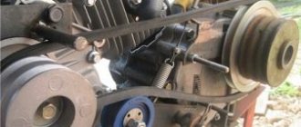
Rice. 4. Single stage single acting piston compressor
A piston compressor is mainly composed of a working cylinder and a piston; has suction and discharge valves, usually located in the cylinder cover. To impart reciprocating motion to the piston, most piston compressors have a crank mechanism with a crankshaft. Piston compressors are single and multi-cylinder, with vertical, horizontal, V or W-shaped and other cylinder arrangements, single and double acting (when the piston works on both sides), as well as single-stage or multi-stage compression.
The operation of a single-stage air piston compressor (Fig. 3) is as follows. When the crankshaft 1 rotates, the connecting rod 2 connected to it imparts return movements to the piston 3. In this case, in the working cylinder 4, due to an increase in the volume enclosed between the piston bottom and the cylinder cover 5, a vacuum arises and atmospheric air, overcoming with its pressure the resistance of the spring holding the suction valve 9, opens it and enters through the air intake (with filter) 8 into the working cylinder. During the reverse stroke of the piston, the air will be compressed, and then, when its pressure becomes greater than the pressure in the discharge pipe by an amount capable of overcoming the resistance of the spring pressing the discharge valve 7 to the seat, the air opens the latter and enters pipeline 6. When the gas is compressed in the compressor, it the temperature rises significantly.
To prevent spontaneous combustion of the lubricant, compressors are equipped with water (pipe 10 for water supply) or air cooling. In this case, the air compression process will approach isothermal (with a constant temperature), which is theoretically the most profitable. A single-stage compressor, based on the safety and economic conditions of its operation, is advisable to use with a degree of pressure increase during compression up to b = 7 - 8. For large compressions, multi-stage compressors are used, in which, alternating compression with intermediate cooling, it is possible to obtain gas at very high pressures - above 10 Mn/m2. Reciprocating compressors typically have automatic capacity control based on compressed gas flow to ensure constant discharge pressure. There are several ways of regulation. The simplest of them is regulation by changing the shaft rotation speed.
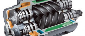
The principles of operation of a rotary and piston compressor are basically similar and differ only in that in a piston compressor all processes occur in the same place (working cylinder), but at different times (which is why it was necessary to provide valves), and in a rotary compressor suction and discharge are carried out simultaneously, but in different places, separated by rotor plates. Other designs of rotary compressor are known, including screw ones, with two rotors in the form of screws. To remove air in order to create a vacuum in any space, rotary liquid ring vacuum pumps are used. The performance of a rotary compressor is usually regulated by changing the rotor speed.
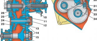
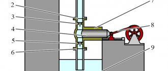
Rotary compressors have one or more rotors, which come in a variety of designs. Rotary vane compressors have become widespread (Fig. 5), having a rotor 2 with grooves into which plates 3 freely fit; the rotor is located eccentrically in the cylinder of the housing 4. When it rotates clockwise, the spaces limited by the plates, as well as the surfaces of the rotor and cylinder housing, on the left side of the compressor will increase, which will ensure gas suction through hole 1. On the right side of the compressor, the volumes of these spaces decrease, the gas contained in them is compressed and then it is supplied from the compressor to the refrigerator 5 or directly to the discharge pipeline. The housing of the rotary compressor is cooled by water, for the supply and discharge of which pipes 6 and 7 are provided. The degree of pressure increase in one stage of a vane rotary compressor is usually from 3 to 6.
Rice. 5. Rotary vane compressor : 1 - air suction hole; 2 - rotor; 3 - plate; 4 — body; 5 - refrigerator; 6 and 7 - pipes for drainage and supply of cooling water
Vane rotary compressors
The design of the vane-rotor unit consists of one rotor, stator and at least eight plates, the mass of which, and therefore the thickness, is limited. The following forces act on the plate during operation: centrifugal and friction/elasticity of the oil film.
Since the oil film normalizes and becomes uniform and sufficient only after several minutes of compressor operation, during starts and stops there is friction of the plates on the stator and, accordingly, increased wear and tear.
The greater the pressure such a block must pump, the greater the pressure difference in adjacent compression chambers, and the greater the centrifugal force must be to prevent the flow of compressed air from a chamber with a higher pressure to a chamber with a lower one. In turn, the greater the centrifugal force, the greater the friction force at the moments of starting and stopping and the thinner the oil film during operation - this is the main reason why this technology has become widespread in the vacuum field (that is, pressure up to 1 bar) and in the area of pressure injection up to 0.3-0.4 MPa.
Since the oil film between the plates and the stator is only a few microns thick, any dust, especially larger solid particles, act as an abrasive that scratches the stator and causes wear on the plates. This leads to bypasses of compressed air from one compression chamber to another and productivity drops noticeably.
Unlike small vacuum pumps, where vane-rotor technology is widely used, in compressors of high capacity and pressure above 0.5 MPa, over time it will be necessary to change the entire unit assembly, since replacing individual plates is effective only if the stator geometry is restored, and Such large stators cannot be restored (polished).
Manufacturers usually do not provide any data on the service life of the vane-rotor unit, since it very much depends on the air quality and the operating mode of the compressor. For gas compressors that pump gas practically non-stop all year round, the service life can actually reach more than 100 thousand hours because the oil film is uniform and sufficient all the time of operation without stopping.
And in industrial use, where the air intake is extremely uneven and the compressor is started and stopped dozens of times a day, most of the time there is no normal oil film inside the unit, which causes aggressive wear of the plates. In this case, the block resource is no more than 25 thousand hours.
Refrigerator electrical equipment
The unit consists of many elements, the interconnection of which contributes to the cooling of the chambers located in the internal part. We will tell you more about the key nodes in the table below.
Table 1. Components that the electrical circuit of the refrigerator includes
| Components | Purpose |
| Electric heaters | They are responsible for supplying heat to the generator in the presence of absorption refrigeration equipment, which has a specific purpose. In addition, these devices are required if there is an automatic ice removal system by heating the evaporator element. Sometimes the device is used to prevent the formation of water drops on the opening of the unit. |
| Engine | This device drives the compressor to work. |
| Wires | They connect the motor, compressor and other components to each other. |
| Paws | Required for refrigerator lighting. |
| Fans | Installed in some models with a forced air circulation system. |
Diagram of refrigeration equipment components
Refrigeration equipment does not operate in manual mode, and in order to ensure autonomous uninterrupted operation of the unit, automation is required. It is thanks to auxiliary equipment that we can change the parameters due to which the temperature remains in a certain mode. Such equipment includes the following components:
- Thermal control relay. The devices help maintain optimal temperature in the chambers of the unit.
- Start relay. Helps start the electric motor.
- Protection relay. Prevents breakdown of compressor elements as a result of high load on the electrical network.
- Devices for automatic removal of ice deposits.
Relay location
Tell me honestly - do you personally know how much electricity a refrigerator consumes per hour, per day, per month? Most likely no. In a special article we will look at this issue in detail. At the same time, we’ll see - maybe there are some ways to save money here?
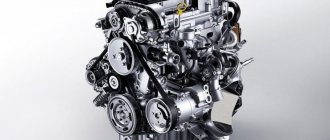
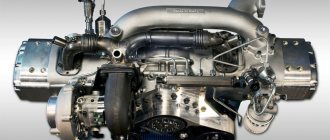
Dynamic compressors
In compressors with a dynamic operating principle, gas is compressed as a result of the supply of mechanical energy from the shaft and the further interaction of the working substance with the rotor blades. Depending on the direction of flow and the type of impeller, such compressors are centrifugal (Fig. 6) and axial (Fig. 7).
Rice. 6. Centrifugal compressor : 1 - shaft; 2, 6, 8, 9, 10 and 11 - impellers; 3 and 7 — ring diffusers; 4 - reverse guide channel; 5 — guide vane; 12 and 13 - channels for supplying gas from refrigerators; 14 - channel for gas suction
A centrifugal compressor mainly consists of a housing and a rotor having a shaft 1 with symmetrically located impellers. The centrifugal 6-stage compressor is divided into three sections and equipped with two intermediate coolers, from which gas enters channels 12 and 13. During operation of the centrifugal compressor, the gas particles located between the impeller blades are subject to rotational motion, due to which centrifugal forces act on them . Under the influence of these forces, the gas moves from the axis of the compressor to the periphery of the impeller, undergoes compression and acquires speed. Compression continues in the annular diffuser due to a decrease in gas velocity, that is, the conversion of kinetic energy into potential energy. After this, the gas flows through the return guide channel into another compressor stage, etc.
Obtaining large degrees of gas pressure increase in one stage (more than 25-30, and for industrial compressors - 8-12) is limited mainly by the tensile strength of the impellers, which allow peripheral speeds of up to 280-500 m/sec. An important feature of centrifugal compressors (as well as axial ones) is the dependence of compressed gas pressure, power consumption, and efficiency on its performance. The nature of this relationship for each brand of compressor is reflected in graphs called performance characteristics.
The operation of centrifugal compressors is controlled in various ways, including changing the rotor speed, throttling the gas on the suction side, and others.
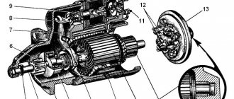
Rice. 7. Axial compressor : 1 - channel for supplying compressed gas; 2 - body; 3 - channel for gas suction; 4 - rotor; 5 — guide vanes; 6 — working blades
An axial compressor (Fig. 7) has a rotor 4, usually consisting of several rows of working blades 6, rows of guide blades 5 are located on the inner wall of the housing 2, gas suction occurs through channel 3, and discharge through channel 1. One stage of an axial compressor consists of a row working and a number of guide vanes. When an axial compressor operates, the rotating blades exert a force on the gas particles located between them, causing them to compress, as well as move parallel to the axis of the compressor (hence its name) and rotate. A lattice of fixed guide vanes provides mainly a change in the direction of the speed of gas particles, necessary for the effective operation of the next stage. In some designs of axial compressors, an additional increase in pressure occurs between the guide vanes due to a decrease in gas velocity. The pressure increase ratio for one stage of an axial compressor is usually 1.2-1.3, that is, significantly lower than that of centrifugal compressors, but they achieve the highest efficiency of all types of compressors.
The dependence of pressure, power consumption and efficiency on performance for several constant rotor speeds at the same suction gas temperature is presented in the form of performance characteristics. Axial compressors are regulated in the same way as centrifugal ones. Axial compressors are used as part of gas turbine units.
The technical excellence of axial, as well as rotary, centrifugal and piston compressors is assessed by their mechanical efficiency and certain relative parameters showing the extent to which the actual gas compression process approaches the theoretically most advantageous one under given conditions.
Jet compressors are similar in design and principle of operation to jet pumps. These include jet devices for suction or injection of gas or vapor-gas mixture. Jet compressors provide a higher compression ratio than jet pumps. Water vapor is often used as a working medium.
Turbochargers are dynamic machines in which gas compression occurs as a result of the interaction of the flow with a rotating and stationary array of blades.
Other classifications
By purpose, compressors are classified according to the industry for which they are intended (chemical, refrigeration, energy, general purpose, etc.). By type of compressed gas (air, oxygen, chlorine, nitrogen, helium, freon, carbon dioxide, etc.). According to the method of heat removal - with liquid or air cooling.
According to the type of drive motor, they are driven by an electric motor, internal combustion engine, steam or gas turbine. Diesel gas compressors are widely used in remote areas with power supply problems. They are noisy and require ventilation for exhaust gases. Electrically driven compressors are widely used in manufacturing, workshops and garages with constant access to electricity. Such products require an electric current of 110-120 Volts (or 230-240 Volts). Depending on the size and purpose, compressors can be stationary or portable. By design, compressors can be single-stage or multi-stage.
According to the final pressure, they are distinguished:
- vacuum compressors, gas blowers - machines that suck gas from a space with a pressure below atmospheric or above. Blowers and gas blowers, like fans, create a gas flow, however, providing the ability to achieve excess pressure from 10 to 100 kPa (0.01-0.1 MPa), in some special designs - up to 200 kPa (0.2 MPa). In suction mode, blowers can create a vacuum, usually 10-50 kPa, and in some cases - up to 90 kPa and work as a low-vacuum vacuum pump;
— low-pressure compressors designed to pump gas at a pressure from 0.15 to 1.2 MPa;
— medium pressure compressors — from 1.2 to 10 MPa;
- high pressure compressors - from 10 to 100 MPa.
— ultra-high pressure compressors designed to compress gas above 100 MPa.
Rice. 8. Example of compressor drawings
Common faults and their solutions
Let's look at the main malfunctions in the operation of an air compressor that you can fix yourself.
The unit engine does not start
First of all, if the engine of the unit fails, you should make sure that there is voltage in the network. It is also a good idea to check the power cable for damage. Next, fuses are checked, which may blow out during a power surge. If any faulty cables or fuses are found, they should be replaced.
The pressure switch also affects engine starting. If it is incorrectly configured, the unit stops turning on. To check the operation of the relay, you need to bleed the air from the receiver and turn on the device again. If the engine starts, carry out the correct (according to the instructions) adjustment of the pressure switch.
In some cases, the engine may not start due to the thermal relay tripping. This usually happens if the unit operates intensively, almost non-stop. In order for the equipment to start working again, you need to give it some time to cool down.
The engine hums but does not start
The humming of the engine without rotating its rotor may be due to low voltage in the network, due to which it does not have enough power to start. In this case, the problem can be solved by installing a voltage stabilizer.
Advice! If the network “sags” due to the operation of any machine, for example, a welding machine, then it should be turned off while using the compressor.
Also, the engine is unable to crank the crankshaft if the pressure in the receiver is too high, and pumping resistance occurs. If this is the case, then you need to bleed the air from the receiver a little, and then adjust or replace the pressure switch. Increased pressure in the receiver can also occur if the relief valve is faulty. It must be removed and cleaned, and if damaged, replaced.
The air coming out has water particles
If the air leaving the receiver contains moisture, then it will not be possible to paint any surface efficiently. Water particles may be present in compressed air in the following cases.
- There is high humidity in the room where the unit operates. It is necessary to provide the room with good ventilation or install a dehumidifier on the compressor (see figure below).
- Water has accumulated in the receiver. It is necessary to regularly drain the water from the receiver through the drain valve.
- The water separator is faulty. The problem is solved by replacing this element.
Decrease in unit performance
The performance of the device may decrease if the piston rings burn out or wear out. As a result, the compression level decreases and the device cannot operate in standard mode. If this fact is confirmed when disassembling the cylinder, then the worn rings should be replaced.
Valve plates can also cause a drop in performance if they are broken or stuck. Faulty plates should be replaced, and clogged ones should be washed. But the most common reason that causes a loss of unit power is a clogged air filter, which should be washed regularly.
Compressor head overheating
The piston head may overheat if the oil is not changed in a timely manner or if a lubricant is used that does not correspond to what is specified in the passport. In both cases, the oil should be replaced with a special compressor oil with a viscosity, the value of which is indicated in the passport for the unit.
Also, overheating of the piston head can be caused by over-tightening the connecting rod bolts, which causes poor oil flow to the bearings. The malfunction is eliminated by loosening the connecting rod bolts.
Unit overheating
Normally, the unit may overheat when operating in intensive mode or at elevated ambient temperatures in the room. If, under standard operating mode and normal room temperature, the unit still overheats, then a clogged air filter may be the culprit. It should be removed and washed, and then dried well.
Advice! This procedure is recommended to be carried out regularly. If the unit is used intensively, the filter should be washed daily.
Knock in the cylinder
Caused by breakage or wear of the piston rings due to carbon deposits. It usually appears if you use low-quality oil.
Also, knocking in the cylinder can be caused by wear of the connecting rod head bushing or piston pin. To fix the problem, these parts should be replaced with new ones. If the cylinder and piston are worn out, air compressor repair involves boring the cylinder and replacing the piston.
Knock in the crankcase
The appearance of a knock in the crankcase during operation of the unit is caused by the following breakdowns.
- The connecting rod bolts are loose. It is necessary to tighten the bolts with the required force.
- The crankshaft bearings have failed. Bearings need to be replaced.
- The connecting rod journals of the crankshaft and connecting rod bearings are worn out. Elimination of these faults involves processing the connecting rod journals to repair size. The liners are also replaced with similar repair-sized parts.
Reduced pressure in the system when the power is turned off
The problem most often occurs due to leaks in one or several elements of the system . First of all, it is worth checking the outlet valve with the piston valve, and also inspect the entire line where the pressure is injected and maintained.
You can adopt an old proven method: lubricate problem areas with soapy water. An air leak will immediately make itself known by the appearance of bubbles. Any cracks that appear are sealed with any sealing material: preferably with a jelly-like consistency to prevent peeling.
The outlet valve is checked in the same way. If the solution bubbles when fixed in the off state, the part must be replaced. In this case, special attention must be paid to sealing: when installing a new faucet, it is imperative to wrap plumbing tape around the threads.
Important! Before carrying out repair work on the air line, it is necessary to bleed all the air in the system. Otherwise, you can not only get serious burns, but also damage the hoses with valves.
Sometimes, to normalize the pressure, it is enough to clean all moving elements - taps and valves from accumulated dirt.
Periodic activation of thermal protection sensors
The obvious reason for this effect is a very high room temperature or operation of the device in direct sunlight. If the climatic conditions are all right, then the problem may be due to insufficient voltage in the network.
Air cooled compressor
A multimeter will help to identify faults of this kind. When the ringing indicators are significantly lower than the standards established by the equipment manufacturer (indicated in the instructions for the device), then we supplement the circuit with a voltage stabilizer.
The engines in classic compressors are air cooled. If the room is poorly ventilated, the device will quickly heat up, and as a result, the thermal protection sensors will work. In this case, it is necessary to move the equipment to a place with sufficient ventilation. It would also be a good idea to check the air filter: clean it of accumulated dirt or replace it altogether.
Unstable engine operation
The problem may occur due to too intense air output or a malfunction of the pressure control sensor. If the power consumed by construction equipment does not correspond to the performance of the compressor, then a significant difference will always affect the operation of the engine.
Therefore, it is imperative to take into account the characteristics of a pneumatic tool, namely, the volume of air consumed per unit of time, and correlate them with the capabilities of the unit. The air flow for the equipment should not exceed 70% of the compressor output.
Pressure switch for compressor
If the technical characteristics of both devices comply with the standards, then the problem is with the pressure switch. The sensor can be repaired, but it is more practical to replace it: fortunately, it is inexpensive and is sold in almost every specialized store.
Increased air flow
First of all, you need to check the air filter: clean or replace if necessary. The next reason is a gas leak in the system. We check every centimeter of the highway, and especially the joints and connections. The latter are treated with sealing material and fum tape.
Some users, after cleaning the receiver from condensate, forget to fix the outlet valve. Sometimes, as a result of increased pressure, it goes down a couple of millimeters on its own: we pull it all the way and check the pressure in the system.
Compressor performance
Compressor performance is usually expressed in units of volume of gas compressed per unit of time (m3/min, m3/hour). Productivity is usually calculated based on indicators normalized to normal conditions. In this case, the productivity of the inlet and outlet is distinguished; these values are almost equal at a small pressure difference between the inlet and outlet, but with a large difference, for example, in piston compressors, the output productivity can fall by more than 2 times at the same speed compared to input capacity measured at zero pressure difference between inlet and outlet. Compressors are called booster if the pressure of the suction gas significantly exceeds atmospheric pressure.
Main manufacturers
To choose the right refrigeration equipment, you need to navigate its “contents”. And the main unit responsible for reliability, energy consumption and performance is the compressor.
The American company TECUMSEN is considered the leader in the production of piston crank models. Many factories in Europe and Asia operate under its licenses.
Among European manufacturers, the Italian concern EMBRACO sells the most compressor motors. The factories of this concern in Europe, Brazil and China produce about 20 million units per year, and they are installed on refrigerators from such a well-known manufacturer as LIEBHERR.
The ELECTROLUX concern owns several brands of refrigerators. The volume of our own production of motor-compressors reaches about 12 million units per year, and they are known under the following brands:
- Austrian Verdichter;
- Italian Zem;
- Spanish Unite Germetique;
- American Kelvinator.
The Danish company DANFOSS has a very good reputation. Its products are quite satisfactory for such reputable refrigerator manufacturers as the BOSCH and SIEMENS concerns.