Working principle of plunger pump
The design of a plunger pump is shown in the figure.
A cylindrical plunger 4 is installed in chamber 7. A krypton-connecting rod mechanism 8 sets the plunger in motion.
When the plunger moves to the right (according to the diagram), the volume of the working chamber will increase, the pressure in it will begin to fall, under the influence of external pressure, the pressure check valve 3 will close, and the suction check valve 5 will open. The liquid, due to the vacuum created in the working chamber, will begin to flow from source 9 into the pump cavity through suction line 6.
When the plunger moves to the left, the volume of the working chamber will decrease, and the pressure in it will begin to increase. Under the influence of this pressure, the pressure valve will open and the suction valve will close. Liquid from the working chamber will be displaced into pressure line 2 and supplied to consumer 1.
After the piston reaches its extreme position, the cycle will repeat.
What is the difference between plunger pumps and piston pumps
According to the principle of operation and hydraulic characteristics, plunger machines are similar to piston pumps. The difference lies in the design of the working bodies, unlike the piston, the plunger moves without touching the walls of the working chamber, the tightness of the chamber is ensured by a stationary sealing gland located in the pump housing.
Advantages of plunger pumps
Compared to a piston pump, a plunger pump has the following advantages:
- Processing the outer surface of the plunger is technologically simpler than processing the inner surface of the sleeve.
- Replacing the outer fixed seal is easier than replacing the movable piston seal.
Calculation of plunger pump flow
The ideal flow of a plunger pump is determined by the volume of the displacer and the speed of the drive shaft.
- where V is the effective volume of the plunger;
- S is the cross-sectional area of the plunger;
- h—plunger stroke;
- n - rotation speed
To calculate the actual flow, it is necessary to take into account the volumetric efficiency of the pump:
If the pump has several pumping units, then the calculated flow must be multiplied by the number of units.
Fighting pulsation [edit | edit code ]
One of the disadvantages of piston pumps, like other positive displacement pumps, is the pulsation of flow and pressure. Pulsations can be reduced by arranging several pistons in a row and connecting them to one shaft so that their operating cycles are shifted in phase relative to each other at equal angles. Another way to combat pulsation is to use a differential pump activation circuit (Fig. 2), in which liquid is pumped not only during the forward stroke of the piston, but also during the reverse stroke.
Double-acting pumps are also widely used, in which both the piston and rod chambers have (in contrast to the differential switching circuit) their own valve distribution system. Such pumps have a lower pulsation coefficient and higher efficiency than single-acting pumps (Fig. 1).
To combat pulsation, hydraulic accumulators are also used, which store energy at the moment of greatest pressure, and release it at the moment of pressure drop.
Plunger Pump Indicator Chart
The figure shows an indicator diagram of a plunger pump, taking into account the delay time t 1 of the opening and closing of the valves.
The suction process occurs along line cd, the abrupt change in pressure at the beginning of the suction process is caused by the fact that the opening of the suction valve does not occur instantly, and the liquid has inertia.
The injection process occurs along line ab; the pressure surge at the beginning of the injection process is caused by the opening of the pressure valve, as well as by the inertia of the liquid.
The area of the indicator diagram reflects the work that the piston imparts to the fluid per revolution.
Source of the article: https://hydro-pnevmo.ru/topic.php?ID=225
How does a plunger pump work and what does it look like?
What is a plunger pump? This is a positive displacement pump. That is, liquid pressure is created by changing the volume of the chamber. When the volume of the chamber increases, a vacuum is created in it, and liquid is sucked in. When the volume decreases, the liquid contracts and the pressure increases.
Diagram of operation of a plunger pump
In the figure we see the presence of valves. The plunger goes to the right - suction - the inlet valve rises, the outlet valve closes. Water fills the chamber. The plunger moves to the left - discharge - the inlet valve closes, the outlet valve rises. Water rushes to its destination.
The same principle is used in piston pumps. The difference between the pumps and each other lies in the injection element. Piston pumps use a piston. In plunger type – plunger. In piston pumps, the most valuable part is the cylinder in which the piston runs. Great demands are placed on the manufacture of this element. Namely, the internal diameter must be within tight tolerance along the entire length.
In the plunger type there is a strict tolerance for the manufacture of the outer surface of the cylinder. Which is much easier to achieve from a technical point of view than boring and finishing the internal diameter.
Description of the plunger and its features
When working with high pressures, plunger-type submersible devices are often purchased. The equipment creates the necessary pressure in the water supply system.
The plunger is capable of working not only with water, but also with any other liquids. The main thing is that they have low viscosity and are not able to interact with the metal parts of the device. The operation of the device is based on dosage. The plunger unit can be manual or automatic. The dosing pump pumps liquid due to high pressure.
The plunger can work with both water and other liquids
If you study the design and the essence of the work in advance, the repair will not cause difficulties. Automatic plunger belongs to oil industry and drilling equipment. But a manual unit can be used to pump water or other liquid.
Read also: Purpose of hydraulic elevator g 600
Features of the plunger device:
- The supercharger maintains the highest pressure possible;
- The vacuum plunger can pump viscous liquids and material with abrasive particles;
- Can be safely used in the field.
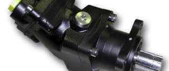
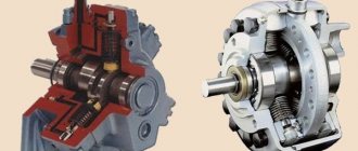
Axial plunger pumps have a piston operating principle. But the design of the working tool has distinctive features. Instead of a piston, a hydraulic pump has a plunger in the shape of a hollow cylinder. It moves in the sealing gland, but does not come into contact with the working chamber. But the hydraulic characteristics of the pump and axial-plunger products are similar. Plunger equipment is easier to use and repair because it has fewer wear parts.
Due to their good performance properties, such pumps are widely used in processing and chemical plants, as well as in a number of highly specialized areas.
Nowadays, automatic plunger devices can be found less and less often in the water supply and sewerage networks. But a manual unit is used in small wells to raise water. An axial-plunger unit for viscous liquids can be used as a dispenser in everyday life.
Plunger pump design
Let us analyze the design of plunger-type pumps using the example of a dosing pump.
Single plunger dosing pump
Electric motor - 1 rotates worm - 2, which is attached to the motor shaft with a coupling. In mesh with the worm there is a worm wheel - 3. An eccentric - 4 is attached to this wheel, which can be located closer or further from the center of the worm wheel. The eccentric position is easily adjusted mechanically. The eccentric is fitted with a connecting rod -5, which pushes the plunger -6.
Suction ball valve - 7 opens when the plunger moves to the left. Water fills the cylinder - 9. In the next phase of the plunger movement, the volume of the chamber is reduced, the suction valve lowers, the discharge valve - 8 rises. Water goes to the consumer.
The stroke of the plunger changes depending on the position of the eccentric. If the eccentric is installed in the center of the worm wheel, then the stroke of the displacer (plunger) is zero. At the maximum distance from the center, the displacer stroke is maximum. That is, the pump performance can be changed from zero to maximum. That's why it's called dosing.
How to adjust the oil supply to a chainsaw chain?
Adjusting the oil supply level is necessary when operating the tool under difficult conditions. The supply level is controlled by a shaft with an eccentric mounted on it, which rests on the pump plunger.
Rotation of such a shaft displaces the plunger relative to the longitudinal axis. This allows you to increase or decrease the volume of the pump’s discharge chamber and quite accurately adjust the level of supply of the working fluid. To do this, at its lower end there is a groove with which adjustment is made.
As a rule, the screw is accessible from the bottom of the chainsaw. For example, in order to adjust the oil supply to the saw set of chainsaws of the Ural family, you must perform the following steps:
- At the bottom of the saw, next to the bar, find the adjusting screw. It is located next to the stamping, which shows the direction of its rotation;
- Use a screwdriver to turn the shaft in the direction of increasing or decreasing the oil supply level.
When performing these actions, remember that the shaft is designed to rotate up to 90⁰. Exerting too much force will lead to breakage of the screw retainers and possible interruption of oil supply to the friction surfaces.
Video instructions can be viewed by following the link
Axial plunger pump
Diagram of an axial plunger pump
It should be noted that an axial plunger pump is often called an axial piston pump. These two terms describe the same mechanism. Axial indicates that the cylinders are located along the axis of the side of the cylinders.
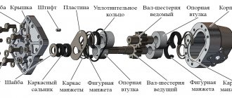
Thrust disk - 1 rotates on axis - 2, which is at an angle to the axis of the cylinder block. The spherical head of the connecting rod - 3 is connected to the thrust disc. When the disk rotates, the connecting rods - 4, following the head - 3, extend and retract the pistons (plungers) - 6, which leads to the suction and injection of water through the holes of the distributor spool - 7. The number of pistons varies from 5 to 9.
For some pumps, the angle γ can be changed arbitrarily. The pump performance changes accordingly. The larger it is, the greater the performance. The angle of the thrust wheel axis to the block axis cannot be more than 45 degrees.
The diagram shows a pump in which the drive shaft rotates the thrust disc. The cylinder block is stationary. Axial plunger pumps are also used, in which the cylinder block rotates and the thrust disc is stationary.
Classification
All plunger-type units, be it a Hawk brand pump or another manufacturer, are divided into several types:
- with horizontal cylinders;
- with vertical arrangement of cylinders;
- vacuum;
- multi-plunger;
- manual;
- auto;
- with sealed cylinders;
- multi-cylinder.
High Pressure Plunger Pump
The simplicity of the design of plunger pumps makes them indispensable in many industries. Compact, inexpensive, durable. Easy maintenance. Pressure from 100 to 3000 atm. Capacity from 200 to 3000 liters per minute.
They produce both stationary and mobile installations on a car chassis. Special anti-vibration supports are used that dampen pump vibrations.
The pump drive is electric or internal combustion engine.
Transmission - elastic coupling, V-belt drive - for an electric motor.
Cardan shaft or clutch - for internal combustion engines.
Safety devices to prevent pressure and temperature from exceeding permissible limits - suction stabilizers.
Self-cleaning filters are an important component of the pumping system.
Replacing the oil pump using the example of a Chinese saw Partner
The oil pump is a fairly reliable element of the chainsaw. However, during operation, malfunctions may occur, the elimination of which requires its replacement. For example, to dismantle the oil pump on a “Partner” chainsaw, you must perform the following steps:
- Unscrew the bolts securing the crankcase cover;
- Remove the cover;
- Move the saw chain to the side and remove the bar;
- Remove the saw chain;
- Remove the air filter housing and the filter itself;
- Remove the spark plug;
- Unscrew the starter cover and remove it. This is necessary so that during the process of cranking the engine crankshaft, the ratchet teeth do not deform and the starter does not break;
- While turning the flywheel, set the piston at top dead center (directly below the spark plug hole) and insert a pre-prepared fabric harness into it. This will help fix the piston in one position and protect the walls of the combustion chamber from mechanical damage;
- Using a puller, unscrew the clutch retaining clip. Unscrewing must be done clockwise. To do this, some models have a stamping with an index arrow and the inscription “Off”;
- Remove the friction element, drum and clutch bearing;
- Remove any remaining dirt formed during work;
- Using a screwdriver, move the cover lock to the side and remove it;
- Unscrew the screws securing the pump;
- Carefully, using a screwdriver, pry the pump housing up and lift it to the side and remove it from the mounting socket. After this, it is necessary to turn off the supply and suction lines.
Installation of a new pump is carried out in the reverse order.
We also recommend watching the video instructions, the author of which explains in detail and shows how to replace the oil pump on a Partner chainsaw.
Application:
- Cleaning any surfaces from paint;
- Cleaning pipes in various systems;
- Cleaning the internal surfaces of containers;
- Cleaning of furnaces, boilers, heat exchangers;
- Cutting concrete, brick, cement;
- Removing putty, rubber, corrosion from any surfaces;
- Removing markings on asphalt
- Cleaning up graffiti
- Roughening surfaces for subsequent gluing;
- Cleaning of railway cars from the inside;
- Desalination of salt water;
- Water purification by reverse osmosis;
- Crushing stones, soil;
- Cutting leather, wood, plastic;
- Removing refractory resins from surfaces;
- Removing waste from the bottom of cars put in for repairs.
Source of the article: https://principraboty.ru/princip-raboty-plunzhernogo-nasosa-chto-takoe-plunzhernyy-nasos/
Piston and plunger pump
The piston liquid pump is one of the first representatives of pumps. Mechanical displacement of liquid is one of the first principles of liquid pumping.
A distinctive feature of piston pumps from other volumetric hydraulic machines is the irreversibility of their effect on water. In other words, such pumps cannot operate as hydraulic drives.
The content of the article
Currently, the design of the piston pump has undergone many improvements and the modern version has a robust housing and has wide interaction capabilities.
Working principle of a piston pump
The operation of a piston liquid pump is based on the displacement principle. The main working parts of such equipment are: a cylinder and a piston. The piston moves in the cylinder in a reciprocating motion.
The operation of a piston pump generally looks like this:
In the cylinder (position), the piston moves (position 7), rigidly connected to the rod (position 9), which is the executive part of the drive crank mechanism. When the piston moves “to the right”, the useful volume of the cylinder, i.e. the volume filled with liquid, increases, As a result, the pressure in it decreases.
The suction valve (position 4) rises, the liquid, under the influence of external pressure on its surface, most often atmospheric, enters the cylinder through the suction valve (position 1), the open check valve (position 2) and the suction pipe (position 3).
When the piston moves “to the left,” the liquid that previously entered the cylinder is pushed out by the moving piston. The pressure in the pump cylinder increases. The suction valve (position 4) closes, and the discharge valve (position 5) rises and the liquid from the cylinder enters the discharge line (position 6). The supply of liquid to the discharge pipeline occurs due to the displacement of previously sucked liquid from the cylinder by a moving piston.
Adjustment and repair
Any unit is subject to breakdowns. Their reasons may be different. Many problems can be solved by repair.
Read also: What is the temperature in a blast furnace
Possible causes of breakdowns:
- Wear of the unit. The engine runs loudly and unevenly.
- Use of low quality diesel. The pump's fuel acts as a lubricant. But if diesel fuel contains some impurities, then the lubricating function becomes more difficult, and this leads to breakdowns.
- Malfunction of electronic devices.
To repair a high-pressure pump, it is necessary to replace worn parts. To do this you will have to disassemble the device. You can do the repairs yourself. But you will need the necessary tools and knowledge about the structure of the structure. However, it is best to seek help from qualified specialists.
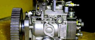
The plunger pump can be oil or water. At the same time, the piston device is offered in double action and even triple action. The choice of devices is quite wide, and the mechanism of action is simple. When choosing a pump, it is recommended to pay attention to Hawk products.
Hydraulic systems have found application in many industrial areas. Hydraulic pumps are important in performing their functions, ensuring efficient operation of the system. They come in different types and purposes, which explains the differences in the principles of operation of the mechanisms.
In addition to the main function of supplying the required fluid under a certain pressure, the hydraulic pump can serve as a drive for other devices. One of the most common is the so-called plunger pump. It is a simple-action device that increases operating efficiency, the main part of which is created in the form of a plunger.
