- home
- Media center
- Articles
- Compressor performance ZIL 130
Menu
- News
- Articles
- Video materials
- Photo materials
- Publication in the media
- 3D tour
29.06.2020
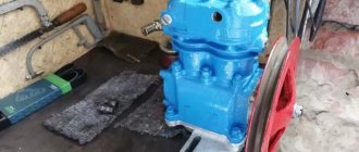
To ensure high-quality brake operation, it is advisable to use a ZIL 130 compressor. This is a universal tool used in many areas of activity. Experienced drivers prefer to find out in advance what performance is found in the ZIL 130 compressor, and why it is advisable to choose a part manufactured before 2010 when assembling it yourself.
Suspension and frame
A distinctive feature of the frame is the channel section, riveted and stamped with special cross members. The rear of the dump truck is equipped with a special towing hook. The latter has a latch. If we talk about the front part, then its parts are placed without a latch.
The spring secures two axles (rear and front). They are fastened using detachable lugs. Springs have sliding ends.
At the front of the suspension there are shock absorbers of several types: hydraulic, telescopic and double-sided. It is worth noting that the suspension design was originally borrowed from the 4th generation VAZ.
Engine
The ZIL-130 truck is equipped with an 8-cylinder 4-stroke engine from an identical manufacturer. The working volume is 5969 cm³.
Other technical indicators include:
- power 150 hp subject to the existing limitation of 3200 rpm;
- the cylinder diameter is 100 mm, the stroke piston in the cylinder is 95 mm;
- compression 6.5;
- torque 1800-2000 rpm;
- Fuel consumption is 29 liters if the condition is met that the average speed is 60 km/h.
The cylinders in the engine are located at an angle of 90⁰. Sleeves equipped with durable rubber seals in the form of rings are located in the lower part of the cylindrical block. A pair of heads are made of a special alloy with aluminum and are equipped with guide valves. The pistons are also made of aluminum alloy. In addition, in terms of design, three compression rings have been added here, two of them are chrome-plated cast iron and one is made of steel.
Steel connecting rods with I-section. Main bearings with thin walls can replace each other in operation. The inserts are made of aluminum and steel. The flywheel is made of high-quality cast iron, surrounded by a crown of heavy-duty steel, so that there are no problems when starting the starter. Camshaft with five bearings.
Regarding steel valves, they differ in design and design. The intakes are located on the block cylinder head. They are put into operation via the camshaft. The exhaust valves are distinguished by a specific overlap and are equipped with a forced valve that forces the structure to rotate. Pushers with mechanics are made of steel with a special cast iron surfacing. The rocker arms are equipped with bushings made of bronze.
The fuel tank is located under the platform with a volume of 170 liters. The feed chain involves the forced supply of fuel through the B-10 pump. The fuel is heated in the gas pipeline.
As for the cooling system, it is liquid and circulates forcibly. Radiator in the shape of a snake, three rows. The thermostat is located in a special cavity in the pipe for transporting liquid.
Why doesn't the compressor pump?
Currently produced compressor equipment is reliable and durable.
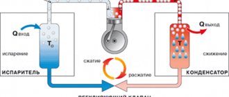
Despite the fact that the basis is the same units, thanks to modern developments and technical progress, dramatic changes have occurred for the better. The equipment has become more compact, while maintaining the same power; screw compressors are very popular due to their excellent performance characteristics. The use of innovative materials has made it possible to increase the service life of most parts. To extend the life of spare parts, lubricating fluids are used, to which special additives are added. For control, most compressor models use a control panel, which can easily start and stop the unit. All information about the time worked and the amount of compressed medium produced is displayed on the console. In some models, information about possible problems is displayed on the display.
Unlike industrial compressor equipment, household models also have various sensors, but there is no remote control on which all the information is displayed, which most often creates a problem. For example, if a temperature sensor receives a signal about a slight deviation from the normal temperature, it signals a malfunction and stops the engine. This case is quite complicated, since it is not easy to find out what kind of problem is reducing the temperature readings.
Transmission
The trucks are equipped with a 5-speed gearbox. The gearbox has 2 inertial synchronizers to engage 2nd, 3rd, 4th and 5th gear. The main gear is double, equipped with wheels with spiral teeth. The gear ratio is 6.32.
The drive distribution is carried out on the rear axle, and the front axle in this case is the steering one.
This also includes 2 cardan format shafts. They are fastened using a special intermediate support, which is located on the frame. For strength and force transmission, there are 3 hinges and needle bearings in the gears. All must be lubricated with special means. The rear axle has a housing made of high-strength steel. The axle shafts assume full loading. Standard tire dimensions are 260*508.
Brake control
The pneumatic braking system is equipped with drum mechanisms. They are responsible for its correct operation. All wheels are pneumatically driven, so all actions of the braking system are controlled using a shoe system. It also operates according to a drum pattern.
All this together affects the transmission, which has a mechanical drive. Here, the performance of the ZIL 130 compressor is influenced by its design, which consists of two cylinders. In addition, regular cooling occurs inside the block and the individual head.
The entire piston system of the ZIL 130 air compressor is made of aluminum. The water pump powers the drive. In addition, there is constant lubrication due to the applied pressure.
Plunger repair
If a plunger breaks, repairing the compressor should begin by unscrewing the front crankcase. Next, the protective cap is unscrewed. After this, it is important to remove the two plates that are clamped with rings. If they do not loosen, you can knock them out a little with a hammer. The next step is to inspect the oil seal. As a rule, a large amount of dirt accumulates on it.
If the supercharger is working properly, then everything inside the block should be clean. In this case, the valves are inspected separately. To remove the plunger, it is recommended to use a large wrench. Doing this yourself is problematic due to the fact that you need to constantly hold the piston. In this case, it is more advisable to ask a friend for help.
Source
Distinctive characteristics of the compressor
You can find out what the performance of the ZIL 130 air compressor is from the technical information:
- two-cylinder unit with a diameter of 6 cm each;
- with a working volume of 214 cm³, the design capacity is 210 l;
- The speed of the ZIL 130 compressor is 2000 per minute;
- a pressure of 740 kPa is observed in the pneumatic system;
- power consumption is 21.1 kW.
The output performance of the ZIL 130 compressor depends on the technical condition of the vehicle.
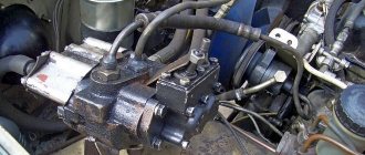
Pressure regulator for the pneumatic brake drive of the ZIL-130 car.
It is designed to automatically maintain the required compressed air pressure in the system. In the housing 10 (Fig. 218) of the pressure regulator, closed by casing 1, there is a fitting 6, in which the valve stem 5 is placed. Spring 2 presses on top of rod 5 through ball 3. Valve spring cap 4 is screwed onto the fitting, secured with lock nut 16. This cap regulates the tension of the spring; When the cap is screwed in, the maximum pressure in the brake system increases. In the central channel of the housing 10 there are two ball valves, inlet 13 and outlet 14. The valves are pressured from above by the rod 5. The central channel is connected to the cylinders through filter 8 and inlet A, and to the compressor unloading device through hole B and filter 7. Housing 1 covers the regulator mechanism from above. A plug 11 is screwed into the body from below.
When the pressure in the brake system is below 560 - 600 kPa, the air from under the plungers 21 (see Fig. 217) escapes into the atmosphere. The plungers lower, releasing the inlet valves 23 (the unloading device is turned off), and the compressor again begins to pump air into the pneumatic systems. When the air pressure in the cylinders is more than 700 kPa, valves 13 and 14 (see Fig. 218) rise upward and spring 2 is compressed by rod 5. In this case, valve 13 opens the entrance to compressed air, and valve 14 closes hole B. Compressed air from the cylinders through regulator and filter 7 passes from hole A to hole B, and then enters the channel in the cylinder block; the compressor switches to idle mode. Gaskets 15 under fitting 6 serve to regulate the pressure at which the compressor switches to idle operation.
Rice. 218 — Pressure regulator for the ZIL-130 car:
1 - casing; 2 — regulator spring; 3 - thrust ball; 4 — adjusting cap; 5 — valve stem; 6 - fitting; 7 - mesh filter; 8 - filter; 9 - sealing ring; 10- pressure regulator housing; 11 - filter plug; 12 — valve spring; 13 — inlet valve; 14 — exhaust valve; 15 — adjusting shims; 16 — locknut of the adjusting cap; A - inlet; B - hole connecting the internal cavity of the regulator with the atmosphere; B is the hole leading to the filter.
What elements does an air compressor consist of?
The element is classified as a piston category unit. A distinctive feature of the work is the transportation of air during the movement of the pistons. The manufacturing scheme involves the use of the following components:
- springs;
- oil seals;
- seals;
- wired catheter with special channels.
The channels are fixed by retaining rings, and the pistons themselves are made of high-quality aluminum. Through special channels, air masses enter the compressor cylinders. Inside, the air flows begin to gradually compress under the pressure of the pistons, and are then transferred to the pneumatic system. After this, there is an outlet through the discharge valve.
A mixed type of lubricant is used. The device is cooled by liquid.
The principle of operation of the pressure regulator for ZIL 130
It is designed to automatically maintain the required compressed air pressure in the system.
In the housing 10 (Fig. 218) of the pressure regulator, closed by casing 1, there is a fitting 6, in which the valve stem 5 is placed. Spring 2 presses on top of rod 5 through ball 3. Valve spring cap 4 is screwed onto the fitting, secured with lock nut 16. This cap regulates the tension of the spring; When the cap is screwed in, the maximum pressure in the brake system increases. In the central channel of the housing 10 there are two ball valves, inlet 13 and outlet 14. The valves are pressured from above by the rod 5. The central channel is connected to the cylinders through filter 8 and inlet A, and to the compressor unloading device through hole B and filter 7. Housing 1 covers the regulator mechanism from above. A plug 11 is screwed into the body from below.
When the pressure in the brake system is below 560 - 600 kPa, the air from under the plungers 21 (see Fig. 217) escapes into the atmosphere. The plungers lower, releasing the inlet valves 23 (the unloading device is turned off), and the compressor again begins to pump air into the pneumatic systems. When the air pressure in the cylinders is more than 700 kPa, valves 13 and 14 (see Fig. 218) rise upward and spring 2 is compressed by rod 5. In this case, valve 13 opens the entrance to compressed air, and valve 14 closes hole B. Compressed air from the cylinders through regulator and filter 7 passes from hole A to hole B, and then enters the channel in the cylinder block; the compressor switches to idle mode. Gaskets 15 under fitting 6 serve to regulate the pressure at which the compressor switches to idle operation.
Rice. 218 — Pressure regulator for the ZIL-130 car:
1 - casing; 2 — regulator spring; 3 - thrust ball; 4 — adjusting cap; 5 — valve stem; 6 - fitting; 7 - mesh filter; 8 - filter; 9 - sealing ring; 10- pressure regulator housing; 11 - filter plug; 12 — valve spring; 13 — inlet valve; 14 — exhaust valve; 15 — adjusting shims; 16 — locknut of the adjusting cap; A - inlet; B - hole connecting the internal cavity of the regulator with the atmosphere; B is the hole leading to the filter.
Pneumatic brake drive for ZIL-130, 131 vehicles
Adjusting the pressure regulator of the pneumatic brake drive of ZIL-130, 131 vehicles
It is recommended to adjust the pressure regulator in the following order. Install the regulator 19 being tested on the stand and connect it to the pneumatic system.
To check the upper limit of pressure, you need to open valve 20 and tap 25 and fill the empty cylinder 22 with compressed air to a pressure of 7.0-7.4 kg/cm2, while simultaneously observing the readings of the pressure gauges. When the pressure in the cylinder reaches 7.0-7.4 kg/cm2 (according to pressure gauge 23), valve 13 (see Fig. 57, a) should open and turn on the regulator, while the reading of pressure gauge 21 (Fig. 57, b) should be the same as pressure gauge 23, i.e. 7.0-7.4 kg/cm2. After making sure of the required pressure gauge readings, you need to close valve 25.
To check the lower pressure limit, open tap 25 slightly, gradually release air from the cylinder and observe the pressure gauges. As soon as pressure gauge 23 shows a pressure of 5.6-6.0 kg/cm2, the needle on pressure gauge 21 should sharply drop to zero. In this case, valve 14 (see Fig. 57, a) will open and the regulator will turn off.
If pressure gauge 21 (see Fig. 57, b) does not show the required pressure when checking both the upper and lower pressure limits, this will mean that the regulator needs to be adjusted. To do this, unscrew the screws, remove the casing 1 (see Fig. 57, a), loosen the lock nut 6 and, by rotating the cap 2, ensure that the outlet valve 14 opens at a lower pressure limit of 5.6 - 6.0 kg/cm2, at which the compressor must turn on and supply air to the pneumatic brake system. When adjusting, you must remember that when you screw the cap on, the pressure increases, and when you unscrew it, it decreases. Having completed the adjustment, you need to secure the cap with a lock nut, and then check the upper pressure limit. If valve 13 does not operate at a pressure of 7.0 - 7.4 kg/cm2, then the upper pressure limit should be adjusted and thereby the valve stroke should be adjusted. To do this, unscrew the seat 16 assembled with the rod 5, thrust balls 4 and spring 3. Then, by changing the number of shims 17, ensure that the inlet valve 13 opens at an upper pressure limit of 7.0 - 7.4 kg/cm2, at which the compressor must be switched off from operation. When adjusting, you must remember that with an increase in the number of gaskets 17, the pressure decreases, and with a decrease, it increases.
When removing seat 16, it is recommended to secure the regulator body 9 in a vice vertically, preventing valves 13, 14 and spring 12 from falling out of the cavity of seat 15.
At the same time, it is recommended to unscrew plug 10, remove filter 11, blow it out, insert it back and secure the plug, as well as clean filter 8 and blow through channel 7.
What items need to be checked during scheduled maintenance?
To maintain the normal operation of the device and the performance of the ZIL 130 compressor, it is recommended to pay attention to a number of technical points:
- how firmly the compressor is attached to the motor;
- how tight are the stud nuts securing the head;
- how securely the tripod is secured;
- It is recommended to check the belt tension daily.
During maintenance, it is advisable to clean the piston channels, seat, and valves. It is advisable to perform these actions with a mileage of 50-60,000 km.
see also
Comments 8
If the valves are not ground in, may it not pump?
The compressor is indestructible!))) the main thing is to figure out where to turn what)
Got it. It turned out that the valve was touching a coating of rye around the circumference and did not move.
I have a question. I changed the seats and valves in the head, when I tightened everything up, I tried the valve travel, but it wasn’t there, what’s the matter? That is, the upper screw presses the valve tightly to the seat...
To grind the valve to the seat, you need to put a rubber hose on a drill and “fiddle” with the paste so that the valve rotates on the seat. It can also be caused by weak valve springs.
There should be no air coming out of the receiver if everything is properly ground in. Yes, the valves and seats need to be ground in.
I was working on this today. I don’t understand how you ground them in... I ground them sideways on sandpaper for half a day! It's better to feel it with your fingers. but the infection gets very hot. The metal is very durable. As a result, the receiver works. I asked a question about koapans. maybe you know. namely, you forced air into the receiver and turned off the compressor. Now the question is... should the valves hold air? does it hiss or not? It’s not just the valves that need to be ground in, but also the valve seats.
Checking the compressor's performance
It is recommended to perform all actions step by step:
- start the engine;
- wait until the pressure in the pneumatic system reaches a level of 7 kgf\cm²;
- shut off the engine;
- remove the hose that connects the ZIL 130 compressor and the air filter (usually made of high-quality rubber). At this moment, the pressure gauge should show a non-critical drop in pressure. If air is passed through, a characteristic sound appears;
- then wait until the pressure level drops to 6 kgf/cm², then remove the pipe through which air, the rocker arm and the spring are supplied;
- remove the rod and socket. It rises up;
- remove the fitting from the socket.
If the need arises, the compressor should be inspected for technical faults. It is important to pay attention to the condition of the O-rings. If there is even minimal damage, it is recommended not to delay replacement.
Replacing the seal
To replace the seal yourself, it is important to carefully inspect the seal. As a rule, a lot of soot accumulates on it. It should also be noted that the seals wear out due to overheating of the pad. This happens due to clogged tubules. To correct this situation, it is recommended to unscrew the protective cover of the compressor. After this, the rings are unscrewed. Next, all that remains is to extend the rocker arm. New linings are installed on a well-cleaned surface. Prices for new ZIL-130 spare parts are quite reasonable.
How to repair components
It is important to note that performance directly depends on the presence of technical breakdowns. The first signs are the presence of an uncharacteristic sound, knocking. Also, oil can gradually enter the car interior:
- chips or cracks appear on the catheter. To eliminate a malfunction, a complete replacement of the structure is often required if the faults or flaws are located on the walls. If the damage is located on the flange and is small in size, then they are often welded;
- To check the cylindrical tightness, it is recommended to lower it into a bath of water and fill it with water, while high pressure should be present. If damage exists, then air bubbles gradually emerge. Repairing problems of this nature is carried out by boring the containers. It is also possible to perform honing according to dimensions;
- if the bearings stop working, then pressing is carried out and then replaced with serviceable components;
- if the connecting rod journal wears out beyond the digital value of 0.05 mm, the entire crankshaft should be completely replaced;
- To repair the upper head of the connecting rod, the bushing must be pressed in and holes corresponding to the dimensions must be made. The diameter is 14.019 mm.
Compressor:
- drive gear;
- lock washer;
- gear fastening nut;
- seal;
- seal spring;
- segment key;
- crankshaft;
- ball bearing;
- crankcase;
- connecting rod bushing;
- connecting rod;
- cork;
- oil scraper ring;
- piston pin;
- compression ring;
- piston;
- cylinder head;
- cylinder head gasket;
- cylinder block;
- coolant supply elbow;
- reflective plate;
- rear crankcase cover gasket;
- rear crankcase cover;
- compressor bottom cover gasket;
- lower crankcase cover.
Plunger mechanism
The plunger mechanism of this compressor is used with a bearing row. Experts say that the part is able to withstand heavy loads at high speeds. However, it is important to note that the inlet valve needs frequent cleaning. In this case, the channel becomes clogged quite often. To check it, the crankcase is unscrewed. You will also have to remove the cover. An adjusting screw is used to adjust the plunger. When the cover comes out, you can install a large screw. In this case, it is necessary to select the appropriate protective ring. To solve problems with abrasion of the lining, special means are used to seal the block. Some experts recommend periodically cleaning the tubules.
Basic and serial modifications
An interesting fact is that before the design of the ZIL 130 it was planned to be used as a base for unified vehicles that should perform various economic tasks. After completion of production, it was confirmed that the vehicle was capable of performing the assigned tasks. In the line of models, including experimental ones, there are about several dozen options.
So, for example, in parallel with the classic ZIL-130, the 130G was produced, which has an extended wheelbase of 4.5 m, as well as the 130-B and 130-C series. The latter option is intended for operation in the Far North and tropical climates.
Until the end of the 80s, the car had optimal potential for export sales. In this case, the equipment requires the use of a 140-horsepower diesel engine from. Gradually, a large number of basic and experimental modifications appeared on the market, which were popular in India, Iraq, and Syria.
Instructions for making your own compressor
First, you will need to determine the tasks for the operation of the future unit. As a rule, reconstruction will be required in a situation where a long service life is planned under conditions of increased load. It is recommended to prepare the following materials in advance:
- receiver;
- pressure gauge;
- power point;
- safety valve.
If you plan to make an air compressor yourself, you must transfer torque correctly and without errors. Before you begin assembly, it is recommended to consider a number of features:
- Torque. If you plan to use a pulley or belt to connect the power plant when connecting, you need to purchase a higher power motor. Therefore, it is recommended to use a gearbox for these purposes, despite the high price.
- Engine. This part is one of the key ones, so it is recommended to select it based on the technical features of the compressor. To achieve the required rotation speed of the system, which is from 2 thousand revolutions per minute, you need to calculate the minimum pressure. Then the engine begins to operate normally without heavy loads. If you plan to use the vehicle for a short time, then you can be guided by a power of 1 kW. Higher loads require the use of structures with greater power.
- Receiver. To create it, you will need a space made of durable metal, which will be of medium size. In addition, the package will include a pressure gauge, which is equipped with a pressure regulation sensor. The package must include a pressure gauge equipped with a pressure regulator.
- Cooling system. To avoid overheating, the structural elements responsible for cooling processes are present.
The compressor is fixed on the frame. For this purpose, the location for placement is pre-prepared. After this, the remaining elements and the engine are connected using hoses.
By deciding to make a compressor for the ZIL 130 yourself, you can get a design with high performance. As a rule, it is possible to purchase a number of components through online stores, where the cost is an order of magnitude lower than from official dealers.
To this day, the ZIL-130 compressor with high performance continues to be in wide demand in many areas, including performing economic and industrial tasks. An air compressor based on the ZIL-130 can be made independently, spending a minimum amount of money. However, it is important to carry out the procedure with special care so as not to waste time on rework in the future.
Adjusting the ZIL-130 compressor
At each maintenance it is necessary to check:
- tightening the compressor mounting nuts on the engine head
- pulley fastening
- drive belt tension
- tightening the nuts of the studs securing the head and other fasteners
The nuts of the studs securing the head should be tightened evenly in two steps. The final tightening torque should be in the range of 1.2–1.7 kgf*m.
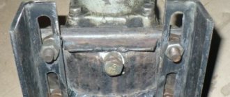
The compressor drive belt must be tensioned so that when a force of 4 kgf is applied, the deflection of the belt branch located between the compressor and fan pulleys is 5-8 mm. Belt tension should be checked daily. The tension of the compressor drive belt is regulated by moving the compressor, which requires loosening the nuts securing the bottom cover to the bracket and using the adjusting bolt 20 to ensure the required tension. After this, tighten the compressor mount and lock the adjusting bolt with a locknut.
The pressure regulator automatically maintains the required compressed air pressure in the system by admitting air into or out of the compressor unloader.
The pressure regulator is adjusted in the following sequence:
- By rotating the cap, it is ensured that the compressor starts working at a pressure of 6.0-6.4 kgf/cm2. When screwing the cap, the pressure increases, when unscrewing it decreases. The cap is secured with a locknut.
- By changing the number of gaskets, a pressure of 7.3-7.7 kgf/cm2 is obtained, at which the compressor is turned off. As the number of gaskets increases, the pressure decreases; with a decrease, the pressure increases.
Source