Repair of YaMZ-238A MAZ gearbox
Page 1 of 3
Caring for the gearbox involves checking the oil level and changing it in the crankcase. The oil level in the crankcase must match the inspection hole. The oil must be drained while hot through all drain holes. After draining the oil, you need to remove the cover at the bottom of the crankcase, which houses the oil pump oil receiver with a magnet, rinse them thoroughly and reinstall them. In this case, you should pay attention not to block the oil line with the cap or its gasket.
| Rice. 1 |
To flush the gearbox, it is recommended to use 2.5 - 3 liters of industrial oil I-12A or I-20A in accordance with GOST 20799-75. With the gearbox control lever in neutral position, start the engine for 7 - 8 minutes, then stop it, drain the flushing oil and fill the gearbox with the oil provided in the lubrication card. It is unacceptable to flush the gearbox with kerosene or diesel fuel.
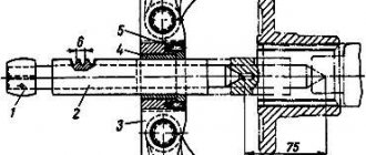
During operation of the gearbox drive, adjustments are possible:
— position of lever 3 (see Fig. 1) for gear shifting in the longitudinal direction;
— position of the gear shift lever in the transverse direction;
— blocking device for telescopic elements of longitudinal thrust.
To adjust the tilt angle of the lever 3 in the longitudinal direction, it is necessary to loosen the nuts of the bolts 6 and move the rod 4 in the axial direction to set the tilt angle of the lever to approximately 85 ° (see Fig. 1) in a neutral position in the gearbox.
Adjusting the position of the lever in the transverse direction is carried out by changing the length of the transverse rod 17, for which it is necessary to disconnect one of the ends 16 and, by unscrewing the nuts, adjust the length of the rod so that the gearbox control lever, being in a neutral position, is opposed to engaging 6 - 2 and 5 - 1 gears , had approximately an angle of 90˚ to the horizontal plane of the cabin (in the transverse plane of the car).
The gear shift drive locking device must be adjusted as follows:
— raise the cabin;
— unpin pin 23 and disconnect rod 4 from fork 22;
— clean the earring 25 and the internal rod from old grease and dirt;
— push in the internal rod until the locking sleeve 15 “clicks”;
— loosen the nut of the earring 25 and, inserting a screwdriver into the slot of the shank of the internal rod, unscrew it until the angular play of the earring disappears;
— holding shank 24 from turning, tighten the locknut;
— check the quality of adjustment. When the locking sleeve 21 is shifted towards the spring 19, the internal rod should be pulled out to its entire length without jamming, and when the rod is pushed inwards until it stops in the grooves, the locking sleeve should move clearly with a “click” until the bushing stops at the lower protrusion of the earring.
When adjusting the drive, the following requirements must be observed:
— make adjustments with the cab raised and the engine not running;
- avoid bending and bending of the outer and inner movable rods;
— to avoid breakage, connect rod 4 to fork 22 so that the hole in the shackle for finger 23 is located above the longitudinal axis of rod 4;
— check the neutral position of the gearbox with the cab raised by freely moving lever 18 of the gear shift mechanism in the transverse direction (relative to the longitudinal axis of the vehicle). Roller 12, when the box is in the neutral position, has an axial movement of 30 - 35 mm, and the compression of the spring is felt.
The gearbox drive adjustments described above should be made when removing and installing the engine and cab.
autoruk.ru
Change of oil
In order to change the oil in a MAZ gearbox, you must:
- Drive about 5-10 km by vehicle to warm up the old oil in the box. At elevated temperatures it becomes liquid and is easy to drain.
- 10-15 minutes after stopping the engine, place the vehicle on a lift or inspection pit.
- Remove the crankcase protective cover.
- Unscrew the plug and check the volume of oil fluid in the manual transmission.
- Check the gasket for wear and, if necessary, replace it with a new one.
- Replace worn filter elements.
- Open the drain hole and drain the oil into a prepared container.
- Fill with new oil fluid.
- Screw on the drain cap.
- Reinstall the clutch protective cover.
- Start the engine and check the oil level at various speeds.
An oil change is necessary when maintenance is carried out or gears are difficult to engage.
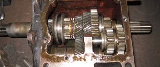
Disassembling the MAZ gearbox
Page 1 of 2
During repairs, the gearbox of the MAZ-5335 car and its modifications is disassembled in three stages: partial disassembly, general disassembly of components.
During partial disassembly, perform the following operations
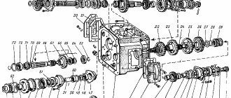
— Remove the oil drain plugs, remove the oil pump intake cover mounting bolts 20 (Fig. 1) from the gearbox complete with the magnet, and remove the intake cover gasket from the intake.
— Unscrew the nuts of the remote gear shift mechanism to the upper roof, remove the spring washers, the mechanism and the gasket of the remote gear shift mechanism from the studs.
— Unscrew the bolts securing the top cover 13 to the gearbox housing 18, remove the top cover assembled with the rod and forks and the cover gasket from the crankcase.
| rice. 1 |
— Unscrew the bolts and remove the power take-off hatch covers and their gaskets.
— Unscrew the nut securing the flange 16, having previously removed the cotter pin, remove the Belleville washer and use a puller (Fig. 2) to remove the flange 16 (see Fig. 1) securing the propeller shaft to the driven shaft of the gearbox.
Unscrew the bolts of the cover 15 of the rear bearing of the driven shaft, remove the cover with the oil seal and the speedometer drive.
— Remove the clutch spring 1, unscrew the nut securing the hose for lubricating the bearing to the clutch housing 4, unscrew the hose assembly from the clutch release clutch and remove the clutch 1 assembly with the bearing from the cover 3 of the rear bearing of the drive shaft.
— Unscrew the coupling bolt of the clutch release fork, remove the spring washer from it and, moving the clutch release fork shaft with the splined end forward, remove the fork. Then knock out the key from the shaft groove and remove the shaft from the hole in the 4th clutch housing.
During general disassembly, perform the following operations
— Unscrew the bolts securing the cover 3 of the rear bearing of the drive shaft 2, remove the cover 3 assembled with the oil seal and remove the drive shaft 2 assembly from the gearbox housing 18, using a puller.
— Move the driven shaft 14 assembly forward until the rear bearing leaves the seat, remove the retaining ring from the annular groove with flares and press the rear bearing and worm 35 of the speedometer drive gear off the driven shaft with a puller. After this, the first gear and reverse gears are removed from the gearbox housing 18 into the shaft 14 assembly and removed from the splined surface of its gearbox.
— Remove the bolts securing the oil pump 25 to the gearbox housing, remove the pump 25 assembly and gaskets.
— Unscrew the bolts of the rear bearing cover of the intermediate shaft 17, remove the cover gasket. Remove the safety wire, two bolts securing the thrust washer of the rear bearing of the intermediate shaft 17 and remove the washer. Take out the axis 26 of the reverse gear block and the block 27 of gears with bearings. Remove the roller bearings and spacer from the block of 27 reverse gears. The intermediate shaft 17 assembly is advanced until the rear bearing of the intermediate shaft exits the gearbox housing housing 18, the retaining ring is removed from the bearing groove with pliers, the bearing is pressed from the shaft and the intermediate shaft 17 assembly with gears is removed from the gearbox housing.
— Remove the cotter wire, unscrew the clutch housing mounting bolts 4, remove the spring washers from the bolts and remove the clutch housing from the gearbox housing 18. Then unscrew the oil level control plug and the oil channel plugs from the gearbox housing.
autoruk.ru
Gearbox YaMZ 238 - with a range multiplier, diagram, device - TD Spetsmash
Many cars of the Minsk Automobile Plant are equipped with engines from the Yaroslavl plant.
Most often, these are engines of the 238 and 239 series, under which a corresponding gearbox is installed. For example, the YaMZ 238 scheme in the base provides for the installation of the same box. It’s the latter that our article will be about... To be completely precise, we will tell you something about those units that are equipped with a special device that allows you to expand the capabilities of the standard box without unnecessary interference in the design. We are talking about a YaMZ 238 gearbox with an increase demultiplier, or as it is otherwise called a divider. We will also use this very word, because on trucks they often use another additional box, which is also called a range multiplier, but it has a slightly different task, and we will talk about it in another article
At its core, the divider is the same gearbox, only it has only two speeds - standard (direct), in which torque is transmitted in the same way as in normal operation, and increased, in which the torque is average in value for two adjacent numbers. That is, for example, the torque of the third gear when the multiplier-divider is turned on will be equal to the arithmetic mean between the torques of the third and fourth direct gears.
Thus, the design diagram of the YaMZ 238 gearbox remains practically unchanged, and since the divider is installed in front of the main box, the number of output speeds remains the same. But by using a divider, the driver receives an additional advantage - it becomes possible to more accurately regulate engine power in accordance with the load and speed.
| Consultation on technical issues, purchase of spare parts 8-916-161-01-97 Sergey Nikolaevich |
Such control allows you to reduce overall fuel consumption and at the same time protects the parts of the main box.
However, if you are with us, then you don’t have to worry about spare parts for the YaMZ 238 gearbox, as well as spare parts for range multipliers and dividers - no matter what you need, SpetsMash will definitely have this part. And don’t worry about the quality of spare parts, because it has been tested by many specialists, including representatives of Yaroslavl Motor. As for the prices for our products... we are not intermediaries, and we don’t need to “jack up” them, so most spare parts are cheaper than at YaMZ itself. You can check!
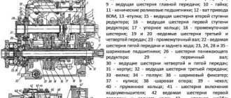
YaMZ 238 gearbox diagram
1 46 1212 1626 Bearing 6-205K 2 240-1307090 Input shaft cuff assembly 3 236-1701478-B Cuff body 4 311810-P2 Ring nut 5 200-1701034 Bearing retaining ring 6 46 1294 5614 Rear bearing 170314L 7 236N-1701027- B Primary shaft assembly 8 236N-1701030-B Primary shaft 9 236-1701043-B Oil drain pipe 9 236-1701043-B Oil drain pipe 10 238-1701122 Thrust washer 10 238-1701122 Thrust washer 11 238-1 701121-10 Bearing sleeve 12 46 2583 2398 Bearing 664818D 12 46 2583 2398 Bearing 664818D 13 238M-1701112 Secondary shaft 1st gear gear 14 236-1701150-B2 Second and third gear synchronizer 15 238-1701113 Spacer sleeve gears 16 236-1701135 Bushing 17 238A-1701131 Gear 2nd gear and secondary shaft 18 236-1701138 Bushing 19 238A-1701129 Gear 4th gear of the secondary shaft 20 236-1701144-G Thrust washer 20 236-1701144-D Thrust washer 20 236-1701144-E Thrust washer 20 236- 1701144-Zh Thrust washer 21 236-1701151-A Synchronizer for fourth and fifth gears 22 46 2253 6674 Front secondary shaft bearing 76-592708M1 23 236-1701067-A Thrust ring B-40 23 236-1701067-A Ring B- 40 persistent 24 238-1701140 Reverse gear 25 238-1701280 Reverse clutch 26 238M-1701282 Clutch bushing 27 238-1701283 Spring thrust ring 28 238-1701194 Ring nut 29 46 1274 7501 Po rear secondary shaft bearing 50315A 30 238-1701034 Retaining ring 31 236 -1701145-A Key 32 314001-P Key 33 238M-1701103 Secondary shaft assembly 34 238M-1701105 Secondary shaft 35 310067-P2 Bolt 36 238-1721033 Intermediate shaft thrust washer 37 46 2113 0 869 Rear bearing 3609 38 238N-1701048 Intermediate shaft 39 314000-П Key 40 238А-1701050 1st gear gear 41 238-1701059 Spacer sleeve 42 238А-1701051 2nd gear gear 43 238А-1701053 4th gear gear 44 236-1701057 -B Power take-off gear 45 236N- 1701056-A Constant mesh gear 46 236-1701063 Thrust ring 47 46 2213 4790 Front bearing 6-42308AK 48 238-1701082 Reverse intermediate gear 49 46 2532 1821 Bearing 50 238-1701092 O x gears 51 45 9824 0265 Key 5x10 Link to this page : https://www.kspecmash.ru/catalog.php?typeauto=6&mark=14&model=678&group=67
www.kspecmash.ru
General gearbox assembly – Overhaul – About MAZ
General assembly of the gearbox is performed in the following sequence:
- install the intake mesh with the gasket assembly into the lower hatch of the crankcase 18 (see Fig. 236) of the gearbox;
- the intake cover 20 with the magnet assembly is placed on the mesh and bolts with spring washers are screwed into the aligned holes, tightening them evenly;
- install gaskets and covers on the side hatches of the crankcase and screw the bolts into the aligned holes. Manhole cover gaskets and threaded holes for bolts are lubricated with sealing paste before installation;
- blow out the oil channels and the internal cavity of the gearbox housing with compressed air;
- screw the oil drain plugs and the oil level control plug into the crankcase, having previously lubricated the threaded holes with sealing paste;
- install the intermediate shaft 17 assembly into the gearbox housing with the bearing in the front seat;
- install the retaining ring into the groove of the outer race of the ball bearing;
- press the rear ball bearing onto the end of the intermediate shaft and into the crankcase hole at the same time;
- install a thrust washer on the end of the intermediate shaft;
- screw the bolts into the aligned holes, tightening them to capacity;
- assemble a block of 27 reverse gears with roller bearings and an intermediate sleeve, having previously lubricated the roller bearings with CIATIM-201 grease;
- install the reverse gear block into the gearbox housing 18 with a small ring gear to the rear end of the housing, press the gear block axis 26 into the holes of the nominal or repair size crankcase (see Table 53) so that the flat on the end of the axle faces the rear bearing intermediate shaft;
SizeDiameter of the hole for the front end of the axle, mm (tolerance +23 µm)
Diameter of the hole for the rear end of the axle, mm (tolerance +23 µm)
Diameter of the neck of the front end of the axle, mm (tolerance -8-22 microns)
Diameter of the neck of the rear end of the axle, mm (tolerance -9-27 microns)
Table 53. Nominal and repair dimensions of the mating surfaces of the gearbox housing and the axis of the reverse gear unit
Nominal
1st repair
2nd repair
26 32 26 32 26,2 32,2 26,2 32,2 26,4 32,4 26,4 32,4 - install the cover of the rear bearing of the intermediate shaft on the end of the gearbox housing with the protrusion towards the flat on the axis of the gear block and screw the bolts with spring washers into the aligned holes, tightening them evenly;
- check the rotation of the reverse gear block and the intermediate shaft by supplying compressed air under a pressure of 0.5-0.7 MPa (5-7 kgf/cm2) to the teeth of the gear block. Knocking, grinding and uneven noise are not allowed;
- install the gear 12 of the first gear and reverse gear on the splines of the driven shaft 14 and check the ease of its movement along the splines, remove the gear from the shaft and place it in the gearbox housing 18, blow the driven shaft assembly with compressed air and smoothly install it into the gearbox housing, at the same time installing the first gear and reverse gear on it;
- blow out the channels of the drive shaft with compressed air and install the drive shaft 2 assembled with the bearing into the hole in the crankcase 18, aligning the oil drain tube with the hole in the driven shaft;
- install the retaining ring into the groove of the outer race of the rear ball bearing of the driven shaft 14 and press the bearing onto the rear end of the driven shaft into the hole in the box housing at the same time;
- check the ease of rotation of the shafts by hand. The shafts should rotate easily, without jamming, with the synchronizers and gear 12 in first gear and reverse in neutral;
- press the speedometer drive drive gear onto the rear end of the driven shaft 14;
- install the gasket and cover 15 of the rear bearing of the driven shaft, having previously lubricated the working surface of the oil seal in the cover with CIATIM-201 grease;
- screw bolts with spring washers into the aligned holes and tighten them evenly until failure;
- press the flange 16 of the propeller shaft fastening until it stops;
- put a disc washer on the splined end of the driven shaft, screw on and tighten the nut until the slot of the nut aligns with the hole in the shaft and insert a cotter pin;
- lubricate the screw groove and the working surface of the oil seal in the cover 3 of the bearing of the drive shaft 2 with CIATIM-201 grease, and the sealing gasket of the cover on both sides and the threaded holes in the crankcase for the cover fastening bolts with sealing paste “Sealant”;
- place the gasket on the cover flange, aligning the holes for the bolts;
- install the cover 3 on the drive shaft 2, aligning the oil drain channel in the cover with the throttle bushing in the gearbox housing 18, screw the bolts into the aligned holes, tightening them to capacity, having previously placed flat washers under them, and lock the bolts in pairs with cotter wire with a diameter of 1.2 mm;
- lubricate the sealing gasket of the oil pump 25 on both sides and the threaded holes in the crankcase 18 of the box for the oil pump mounting bolts with sealing paste “Sealant”;
- place a gasket on the base of the oil pump 25, aligning the holes for the bolts, install the pump assembly on the gearbox housing 18, aligning the position of the protrusion of the drive gear shaft shank with the groove in the intermediate shaft 17 and directing the cut part of the base towards the drive shaft bearing cover 3;
- screw bolts with enclosed flat washers into the aligned holes, which are locked in pairs;
- check the rotation of the box shafts by hand, which should rotate easily, without jamming;
- install the upper and lower covers on the clutch housing hatches 4 and secure them with bolts with attached spring washers;
- lubricate the threaded holes in the gearbox housing 18 under the clutch housing mounting bolts 4 with “Sealant” sealing paste;
- install the assembled clutch housing 4 on the end of the gearbox, screw bolts with attached spring washers into the combined holes of the clutch housing and gearbox and secure them in pairs with cotter pins with a diameter of 1.6 mm;
- insert the clutch release fork shaft into the clutch housing bushings 4 so that the splined end of the shaft is on the left when looking at the gearbox from the side of the driveshaft flange;
- check the ease of rotation of the shaft by hand;
- insert a key into the shaft groove;
- pull the shaft out of one bushing, install the clutch release fork on it with the machined pads facing forward;
- screw a coupling bolt with washers into the fork hole;
- align the fork symmetrically with the pipe of the drive shaft bearing cover 3;
- tighten the coupling bolt completely;
- Press the bearing onto the neck of clutch 1 until it stops. After pressing, the inner ring and outer race of the bearing should rotate freely by hand;
- install coupling 1 assembly on the drive shaft bearing cover 3, check the ease of movement of the coupling along the drive shaft cover;
- connect the coupling with springs, inserting their ends into the holes of the coupling and fork;
- secure the clutch release clutch lubrication hose by screwing its ends into the clutch and clutch housing;
- screw angular grease nipples into the tip of the hose attached to the clutch housing and into the holes for lubrication of the clutch release shaft support journals;
- install synchronizers 5, 10, gear 12 of first gear and reverse gear in the neutral position;
- place the gasket on the mating plane of the gearbox housing 18 with the top cover 13, aligning the holes for the bolts;
- install the upper cover 13 assembly on the gasket, aligning the gear shift forks with the grooves of synchronizers 5 and 10 and gears 12 of first gear and reverse gear;
- screw the bolts into the aligned holes and tighten them evenly;
- install the gasket of the remote gear shift mechanism on the studs of the top cover;
- place the remote gear shift mechanism assembly on the gasket so that it is directed towards the splined end of the clutch release shaft, and the gear shift lever fits into the groove of the gear shift rod head;
- put spring washers on the studs, screw on the nuts and tighten them to capacity;
- insert the speedometer drive gear into the cover 15 of the rear bearing of the driven shaft 14, install the cover of the replaceable gears with the driven spur gear shaft and secure with bolts;
- Lubricate the clutch release clutch and the clutch release shaft bushings through grease nipples with universal refractory grease.
General gearbox assembly
maz-auto.info
Not available:
| № | Part code | Name | Quantity per model, pcs. | |
| 1 | 544022-1602940 | A tube | 1 | Not available |
| 3 | 4370-1703410 | Lever arm | 1 | Not available |
| 4 | 555005-1703448 | Shank | 1 | Not available |
| 5 | 64301-1703490 | Traction | 1 | Not available |
| 6 | 551633-1703229 | Lever arm | 1 | Not available |
| 7 | 650136-1703457 | bracket | 1 | Not available |
| 9 | 551633-3903049 | Information plate | 1 | Not available |
| 11 | 374614 | Nut M12x1.5-5N6N | 1 | Not available |
| 12 | 375818 | Washer 12 | 2 | Not available |
| 14 | 404209 | Union | 1 | Not available |
| 17 | 201458 | Bolt M8-6ghx25 | 4 | Not available |
| 19 | 200367 | Bolt M12-6ghx45 | 2 | Not available |
| 20 | 250510 | Nut M8-6N | 4 | Not available |
| 21 | 250975 | Nut M8x1-6N | 1 | Not available |
| 22 | 250977 | Nut M12x1.25-6N | 1 | Not available |
| 23 | 252005 | Washer 8 | 5 | Not available |
| 24 | 252007 | Washer 12 | 1 | Not available |
| 25 | 252135 | Washer 8T | 4 | Not available |
| 26 | 252137 | Washer 12.OT | 2 | Not available |
| 27 | 258025 | Cotter pin 2.5x20 | 1 | Not available |
| 28 | 258038 | Cotter pin 3.2x16 | 1 | Not available |
| 29 | 010-014-25-2-3 | Ring | 1 | Not available |
Can't find the required part from the group Installation of gearbox control drive 6501B5-1700002-030 on MAZ-5440B5 ? Consult our specialists by phone 8-800-700-19-88 or by email. We will definitely help you!