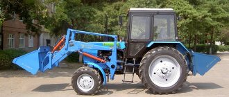
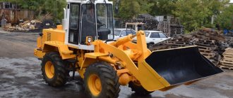
To buy a high-quality front loader that can handle even rocks and frozen soil, you don’t have to go far. It is enough to turn to the famous Belarusian plant MoAZ, which has already proven itself excellent: its equipment works perfectly in the most difficult conditions.
MoAZ loaders
The MoAZ front loader is produced at the Mogilev Automobile Plant. Production facilities, as well as main representative offices, are located in Belarus. The plant was founded in 1935, and since 2006 it has become a branch of BelAZ OJSC. Later, a restructuring was carried out and the company became a branch of the BELAZ-HOLDING holding.
Highly qualified engineers use modern developments and create construction equipment that is considered one of the best in the world. Due to its characteristics and reliability, the equipment is widely used in Siberia, as well as in the Russian Far East. It is used for laying roads, developing oil and gas fields, and is especially popular in quarries or when working in underground deposits.
Among the front loaders, we can highlight the basic model MoAZ-40484. Based on it, modifications have been developed that have several development options.
The first option is to convert the loader into a bulldozer by replacing the working element. The second option is to increase engine power, which entails improved driving characteristics and operating speed.
The MoAZ loader is an all-terrain chassis with all-wheel drive and a loader boom in the front. Mainly, due to its power, it is used in quarries and the mining industry.
Photo of MoAZ 40484 front loader
Possibilities
It is used mainly in quarries for loading semi-rocky and rocky rocks that have been previously blasted or loosened. It also works with light and loose rocks that are removed from the pillar. Thanks to its high breaking force, it is capable of not only loading a vehicle with a carrying capacity of more than 3.5 tons, but also being used as a bulldozer.
MoAZ 40484 description
The front loader MoAZ - 40484 is designed for loading blasted or loosened semi-rock and rock, as well as light and loose rocks selected from the pillar. This is a powerful, rigid, stable vehicle with an articulated frame, equipped with a hydraulic transmission and two drive axles, and has excellent maneuverability and high traction performance. An electro-hydraulic transmission control system, a hydraulic loader control system, service, parking and emergency brake systems with pneumatic drive, as well as an enclosed cabin with heating and ventilation create comfortable working conditions for the driver. Wide versatility of use is ensured by the ability of the loader to load vehicles with a lifting capacity above 3.5 tons. It is equipped with loading buckets with increased volume and various cutting edge options
Assembly and assembly-welding equipment (conductors, stands, installations) is specialized, designed for the manufacture of products of one standard size or a group of similar products. However, assembly equipment components (installation and fastening elements, rotating devices, bases) have universal significance and are used in various assembly equipment. Universal prefabricated fixtures for welding production are a set of normalized parts and assemblies, from which fixtures for assembling and welding various welded assemblies are repeatedly assembled. After manufacturing a batch of welded assemblies, the fixture is disassembled, and the parts and assemblies are used to assemble new fixtures. Universal prefabricated devices are most rational in single, pilot and small-scale production, when using special equipment is not economically profitable.
Design features
The loader chassis consists of two parts, which are connected by a hinge and controlled by hydraulics. There are two driving axles in this machine, which ensures high cross-country ability. The boom is mounted at the front and extends forward, which is what makes this a front loader.
The hydraulic pump takes power from the main engine and performs a wide range of tasks. It provides power to such important components of the loader as the brake system, steering, hydraulic system of the loader boom, as well as the electro-hydraulic transmission.
In a steering system, hydraulics are essential so that they can provide enough force for smooth and precise turning.
The transmission also provides a smooth change in speed, which is very important for the accuracy of the work performed.
The enclosed cabin has a comfortable, adjustable seat and a heating and ventilation system. This will provide the necessary comfort to the operator.
Review of the Belarusian front loader from the MoAZ 40484 plant
To buy a high-quality front loader that can handle even rocks and frozen soil, you don’t have to go far.
It is enough to turn to the famous Belarusian plant MoAZ, which has already proven itself excellent: its equipment works perfectly in the most difficult conditions. Purpose: intended for loading and unloading, construction and installation work at dispersed sites.
Our company sells front loaders of the following brands: MoAZ 40484, Universal 800, UN 053, T-156, PK-65, T-156, V-138, V-140, UN-053, Universal 800, Amkodor 342v L-34 and spare parts to them at low prices, a well-functioning set of quality control measures allows our loaders to stand out from many factories, which is proven by non-returns throughout the entire period of our work.
We deliver equipment to the cities of Chelyabinsk, Yekaterinburg, Moscow, St. Petersburg, Ufa, Kazan, Perm, Tyumen, Omsk, Surgut, Sochi, Rostov-on-Don, Nizhny Novgorod, Novosibirsk, Surgut, Ust-Kut, Krasnoyarsk, Samara, Vladivostok, Khabarovsk, Astana, Ust-Kamenogorsk, Taraz, Karaganda, Aktobe, Taldykorgan, Kyzyl Orda, Kustanai, Pavlodar, Shymkent, Uralsk, Petropavlovsk, Kokshetau, Aktau, Atyrau in Russia and the CIS (Kazakhstan, Belarus, Ukraine)
Specifications
Technical characteristics of the main model with replaceable buckets:
| Characteristics | Indicators |
| Own/laden weight | 29500/3700 |
| Turning radius, m | 8 |
| Engine/power, kW | YaMZ-238B/220 |
| Traction force, kN/t.s. | 125/25 |
| Breakout force, kN/t.s.: | |
| — on hydraulic cylinders of rotation | 224/22 |
| - on boom hydraulic cylinders | 250/25 |
| Bucket volume, m3 | 3,7; 5,0; 6,5 |
| Load capacity, t | 7,5 |
| Dimensions LxWxH, mm | 9520x3300x3750 |
Spare parts for agricultural, road construction and municipal equipment
The whole range of spare parts for agricultural and special equipment from leading domestic manufacturers, countries far and near abroad. Spare parts available for: MTZ tractors, excavators, forklifts, engines, motor graders, asphalt pavers, rollers, truck cranes, combines. All nomenclature and price list on the website AkvilonAvto.com CHUP AKVILONAVTO , Minsk, st. Socialist, 22. Tel.: (+375-17) 210-51-93, 243-55-51, (+375-29) 656-32-90
More advertisements >>>[/td]
Modifications
Let us give an example of several modifications, as well as briefly the main distinctive characteristics:
- MoAZ-40483 has a more powerful engine, which increases the maximum weight of the load, as well as the time it takes to lift the bucket. The loader is equipped with a YaMZ-7512.10 engine with a power of 254 kW. Its carrying capacity is 8 tons.
- MoAZ-40483-030 is the basic previous version, but with an even more powerful power unit - YaMZ-7512, which has a power of 294 kW.
- MoAZ-40486 and MoAZ-40489 are bulldozers based on a standard chassis from the MoAZ 40484 front loader.
| Model | 40486 | 40489 |
| Engine/power | CUMMINS M11C350/261 | YaMZ-7512.10/264 |
| Weight, kg | 36700 | 30400 |
| Traction force, kN | 180 | 180 |
| Turning radius, m | 9 | 9 |
It is also possible to install different working parts and change some components of the loader. However, this is already carried out on special orders.
The video shows the Moaz 40483 loader in operation:
OPERATION MANUAL 40484-3902002-21 RE. FORKLIFT TRUCK MOAZ-40484
OPERATION MANUAL 40484-3902002-21 RE. FORKLIFT TRUCK MOAZ-40484
© URP "Mogilev Automobile Plant named after S.M. Kirov" This "Operation Manual" cannot be reproduced or duplicated in whole or in part without the written permission of URP "Mogilev Automobile Plant".
CONTENTS Sheet PART 1 DESCRIPTION AND WORK…………………………………………………………………………………………………………………………………………… …….1.1-1.30 1.1 PURPOSE OF THE LOADER……………………………………………………………………………………………………………………………………… ………….1.1 1.2 TECHNICAL CHARACTERISTICS…………………………………………………………………………………………………………1.1 -1.22 1.2. 1 Technical characteristics of the loader…………………………………………………………………………………..1.1 1.2.2 Technical characteristics of loading equipment………… ……………………….1.19 1.2.3 Weight of main components and assemblies (in kilograms)……………………………………………………1.20 1.2.4 Refueling capacities ( in liters)…………………………………………………………………………………………………………..1.20 1.2.5 Adjustment data……… ………………………………………………………………………………………………………………………………………….1.21 1.2.6 Replacement buckets (optional)…………………………………………………………………………………………………………………… …………………1.22 1.3 DEVICE AND OPERATION…………………………………………………………………………………………………………………… ………………………………1.23 1.4 CONTROLS AND INSTRUMENTS……………………………………………………………………………………………… …………………….1.24-1.27 1.5 MEASUREMENT INSTRUMENTS, TOOLS AND ACCESSORIES…. 1.28-1.29 1.6 MARKING AND SEALING…………………………………………………………………………………………………………………1.30 1.7 PACKAGING………… …………………………………………………………………………………………………………………………………… …………………………….1.30
PART 2 STRUCTURE AND OPERATION OF LOADER COMPONENTS……………………………………………………..2.1.1-2.14.16
2.1 POWER PLANT………………………………………………………………………………. 2.1.1-2.1.37 2.1.1 Engine mounting…………………………………………………………………………………………………………………… ……………………………………………………2.1.1 2.1.2 Engine fuel supply system…………………………………………………… ……………………………………………………..2.1.1 2.1.2.1 Air filter maintenance……………………………………………………………………………… ……………………………………………………….2.1.5 2.1.2.2 Checking the tightness of the engine air supply system……………………………………………………………………………… ………………………………………………………………………………2.1.7 2.1.3 Engine lubrication system………………… ……………………………………………………………………………………………………………..2.1.9 2.1.4 Engine cooling system…………………………………………………………………………………………………………………..2.1 .10 2.1.4.1 Checking the fan belt tension…………………………………………………………………………………..2.1.14 2.1.5 Starting engine heater PZD-44………………………………………………………………………………2.1.15 2.1.5.1 Technical characteristics………………… …………………………………………………………………………………………………………………2.1.17 2.1.5.2 Design features and operating principle …………………………………………………………….2.1.20 2.1.5.3 Procedure for heating and starting the engine when filling the cooling system with low-freezing liquid……………………… …………………………………………………….2.1.21 2.1.5.4 The procedure for heating and starting the engine when filling the cooling system with water………………………………… ……………………………………………………………………………………………………………2.1.24 2.1.5.5 Heater maintenance……………… ………………………………………………………………..2.1.25 2.1.5.6 Safety precautions and fire prevention measures………………………………… …..2.1.26 2.1.6 Starting heater of the PZD-30 engine………………………………………………………………………………..2.1.27 2.1.6.1 Technical characteristics…………………………………………………………………………………………………………………… …..2.1.27 2.1.6.2 General instructions…………………………………………………………………………………………………………………… ………………………………………………………..2.1.28 2.1.6.3 Design features and operating principle…………………………………………………………… ………………….2.1.29 2.1.6.4 The procedure for heating and starting the engine when filling the cooling system with low-freezing liquid……………………………………………………………………..2.1.33 2.1. 6.5 Procedure for heating and starting the engine when filling the cooling system with water………………………………………………………………………………………………………………………… ………………………2.1.34 2.1.6.6 Maintenance of the starting heater…………………………………………2.1.35 2.1.6.7 Rules for using the starting heater……… ………………………………………………………2.1.36 2.2 POWER TAKE-OFF………………………………………………………. 2.2.1-2.2.3
2.3 HYDROMECHANICAL TRANSMISSION…………………………………………………………..2.3.1-2.3.33 2.3.1 Torque converter…………………………………………………………… …………………………………………………………………………………………………………..2.3.1 2.3.2 Gearbox …………………………………………………………………………………………………………………………………… ………………………………2.3.5 2.3.3 Hydraulic system………………………………………………………………………………… …………………………………………………………….2.3.8 2.3.4 Dismantling the hydromechanical transmission……………………………………………………………… …………………………………………………..2.3.18 2.3.4.1 Disassembling the torque converter……………………………………………………… ………………………………………………………..2.3.18 2.3.4.2 Disassembling the gearbox……………………………………………………………… ………………………………………………………………………………..2.3.19 2.3.4.3 Disassembling the clutch………………………… …………………………………………………………………………………………………………………….2.3.21 2.3 .4.4 Dismantling the hydraulic system components……………………………………………………………………………………..2.3.21 2.3.4.4.1 Dismantling the front pump……………………………………………………………………………………………………………………………………2.3.21 2.3.4.4.2 Dismantling the oil intake and full-flow filter……………………………………………………2.3.22 2.3.4.4.3 Disassembling the spool box…………………………………………………… …………………………………………………………………………………2.3.22 2.3.4.4.4 Disassembling the control mechanism…………………………………………………… ……………………………………………………………………………………2.3.23 2.3.4.4.5 Disassembling the torque converter release mechanism………………………… ..2.3.23 2.3.5 Assembly of hydromechanical transmission units………………………………………………………………………………….2.3.23 2.3.5.1 Front pump assembly……………………………………………………………………………………………………………………………………… ………2.3.24 2.3.5.2 Assembling the spool box and control mechanism………………………………………….2.3.26 2..3.5.3 Assembling the clutch…………………… ……………………………………………………………………………………………………………………………………………. 2.3.28 2.3.6 Assembling the hydromechanical transmission……………………………………………………………………………………………………………..2.3 .29 2.4 CARDAN TRANSMISSION………………………………………………………………………………2.4.1-2.4.4 2.5 DRIVE AXLES……………………… ……………………………………………………. 2.5.1-2.5.11 2.5.1 Adjusting the drive axle………………………………………………………………………………………………………………………… ……………………………2.5.8 2.5.2 Adjusting the tightening of the bearings of the main gear drive gear………………………………………………………………………………… …………………………………………………………………………………………..2.5.8 2.5.3 Adjusting the differential bearings…………… ……………………………………………………………………………….2.5.9 2.5.4 Adjusting the gear engagement of the main gears……………………………………………………… ……………………..2.5.9 2.5.5 Adjusting the gap between the deformation limiter block and the driven gear of the main drive…………………………………………………………… …………………………………2.5.10 2.5.6 Adjusting the wheel hub bearings………………………………………………………………………………………… …………………….2.5.10 2.6 FRAME………………………………………………………………………………………………………………… ….. 2.6.1-2.6.2
2.7 SUSPENSION………………………………………………………………………………………………………… 2.7.1-2.7.10 2.7.1 Suspension maintenance…… …………………………………………………………………………………………………………………………………… ..2.7.4 2.8 WHEELS, TIRES………………………………………………………………………………… 2.8.1-2.8.3 2.9 STEERING CONTROL ……………………………………………………………………………… 2.9.1-2.9.20 2.9.1 Pump…………………………………………………… …………………………………………………………………………………………………………………………………… ……………………………2.9.1 2.9.2 Priority valve………………………………………………………………………………… ……………………………………………………………….2.9.1 2.9.3 Pilot safety valve…………………………………………………………… ……………………………………………………..2.9.5 2.9.4 Hydraulic steering……………………………………………………… ………………………………………………………………………………………………………………………………………..2.9 .6 2.9.5 Flow amplifier………………………………………………………………………………………………………………… ……………………………………………..2.9.9 2.9.6 Turning hydraulic cylinders……………………………………………………………………………… ………………………………………………………………………………………………2.9.9 2.9.7 Oil lines……………………………………………………… …………………………………………………………………………………………………………………………………… 2.9.12 2.9.8 Steering column…………………………………………………………………………………………………………………… ……………………………………………………2.9.12 2.9.9 Steering cardan shaft…………………………………………………… ………………………………………………….2.9.15 2.9.10 Safety valve……………………………………………………………… ………………………………………………………………………………2.9.15 2.9.11 Steering operation……………………………………………………… ………………………………………………………………………………………2.9.15 2.10 BRAKE SYSTEMS…………………………………………………… ……………………………………. 2.10.1-2.10.36 2.10.1 Working brake system…………………………………………………………………………………………………………………… ……………………………..2.10.1 2.10.2 Parking brake system………………………………………………………………………………… …………………………………………..2.10.5 2.10.3 Spring energy accumulator……………………………………………………………… ………………………………………………….2.10.8 2.10.4 Pneumatic drive of brake systems……………………………………………………… …………………………..2.10.10 2.10.4.1 Operation of the pneumatic drive of brake systems………………………………………………………..2.10.14 2.10.4.2 Drive brake valve……………………………………………………………………………………………………………………………………………… ..2.10.16 2.10.5 Compressor…………………………………………………………………………………………………………………… ………………………………………………………………..2.10.18 2.10.6 Water separator…………………………………………………………… ……………………………………………………………………………………………………………………………………2.10.20 2.10 .7 Pressure regulator…………………………………………………………………………………………………………………………………………… …………………………….2.10.21 2.10.8 Anti-freeze………………………………………………………………………………… …………………………………………………………………………………..2.10.23 2.10.9 Double safety valve……………………………………………………… ………………………………………………………………………………………….2.10.25 2.10.10 Brake valve……………… …………………………………………………………………………………………………………………………………… …………2.10.25 2.10.11 Accelerator valve………………………………………………………………………………………………………………………… ………………………………………………………2.10.27 2.10.12 Manual reverse acting brake valve…………………………2.10.30 5
2.10.13 Double-line valve……………………………………………………………………………………………………………………… ……………..2.10.32 2.10.14 Control outlet valve…………………………………………………………………………………………………………… ……………………………………..2.10.32 2.10.15 Air ducts………………………………………………………………………………………… ………………………………………………………………………………………………………….2.10.32 2.10.16 Care of the pneumatic drive of brake systems… …………………………………………………..2.10.34 2.11 ELECTRICAL EQUIPMENT AND DEVICES……………………………………………………2.11.1-2.11. 18 2.11.1 Sources of electrical energy…………………………………………………………………………………………………………………………………………… …2.11.6 2.11.1.1 Rechargeable batteries………………………………………………………………………………………………………………… ……………………………2.11.6 2.11.1.2 Alternating current generator………………………………………………………………………………… …………………………………………………………..2.11.6 2.11.2 Consumers of electrical energy……………………………………………………… ………………………………………………………2.11.6 2.11.2.1 Starter……………………………………………………………………………… …………………………………………………………………………………………………………………………………… ..2.11.7 2.11.2.2 Heater electric motor…………………………………………………………………………………………………………………………………… ……………………….2.11.7 2.11.2.3 Electric motors for windshield wiper and washer……………………………2.11.7 2.11.2.4 Instrumentation…… …………………………………………………………………………………………………………….2.11.8 2.11.2.5 Lighting and alarm system…… ………………………………………………………………………………………………………………….2.11.11 2.11.3 Switching equipment, wires …………………………………………………………………………………………………………..2.11.15 2.12 CABIN AND ELENATURE… ………………………………………………………………………………2.12.1-2.12.8 2.12.1 Cabin…………………………………………………… …………………………………………………………………………………………………………………………………… ……………………………….2.12.1 2.12.2 Driver’s seat……………………………………………………………………………………………… ………………………………………………………………………………………….2.12.3 2.12.3 Cabin heating and ventilation…………… ……………………………………………………………………………………………………………..2.12.6 2.12.4 System air conditioning………………………………………………………………………………………………………………….2.12.7 2.12.5 Plumage………………………………………………………………………………………………………………………………… ……………………………………………………………..2.12.7 2.13 LOADING EQUIPMENT…………………………………………………………………… .2.13.1-2.13.2 2.14 HYDRAULIC SYSTEM……………………………………………………………………………………………….2.14.1-2.14.16 2.14.1 Pumps…………………………………………………………………………………………………………………………………………… …………………………………………………………………….2.14.2 2.14.2 Hydraulic tank…………………………………………………………… …………………………………………………………………………………………………………………………………… ………………..2.14.2 2.14.3 Hydraulic distributor and its control drive………………………………………………………………………………2.14 .5 2.14.4 Hydraulic cylinders…………………………………………………………………………………………………………………… ……………………………………………………….2.14.11 2.14.5 Oil lines……………………………………………………… ………………………………………………………………………………………………………………..2.14.11 2.14.6 Diagnosing the hydraulic system…………………………………………………………………………………………………………………… …2.14.13
3.1 SAFETY PRECAUTIONS…………………………………………………………………………………3.1-3.5 3.2 PREPARING THE LOADER FOR USE…………………………3.6- 3.21 3.2.1 Preparing the loader for operation in the summer………………………………………………………………..3.9 3.2.2 Preparing the loader for operation in the winter…………………… …………………………..3.9 3.3 USING THE LOADER……………………………………………………. 3.11-3.21 3.3.1 Starting and moving in transport mode………………………………………………………3.11 3.3.2 Stopping the loader and engine……………… …………………………………………………… 3.12 3.3.3 Working with loading equipment……………………………………………………………………………………… ………………………………….3.13 3.3.4 Monitoring the operation of the loader………………………………………………………………………………………… …………………………………………………………3.18 3.3.5 Features of winter operation of the loader………………………………………………………………………………… …………….3.20 3.4 RUN-IN OF THE LOADER…………………………………………………………………… 3.22-3.24 3.5 TOWING THE LOADER…………………… ………………………………………………………………………………………………………………….3.25 3.6 LIST OF POSSIBLE MALFUNCTIONS AND WAYS TO ELIMINATE THEM… ………………………………………………………………………………… 3.26-3.43 PART 4 MAINTENANCE OF THE LOADER……………………… 4.1-4.35 4.1 GENERAL INSTRUCTIONS……………………………………………………………………………………………… 4.1-4.3 4.2 PROCEDURE FOR MAINTENANCE OF THE LOADER………. 4.4-4.31 4.2.1 Maintenance procedure…………………………………………………………………………………………………………………4.4 4.2. 2 List of fuels and lubricants…………………………………………………………………………………4.16 4.3 PRESERVATION………………… ………………………………………………………………. 4.32-4.35 4.3.1 Preservation for up to two months……………………………………………………………………………………………………………………. 4.32 4.3.2 Preservation for a period of more than two months…………………………………………………………………………………..4.33 4.3.3 Re-preservation of the loader ……………………………………………………………………………………………………………………………………………. 4.34
PART 5 STORAGE
PART 6 TRANSPORTATION………………………………………………………………………………6.1-6.3 PART 7 DISPOSAL……………………………………………………………… …………………………………………………………………………………………………………..7.1 APPENDICES APPENDIX A. List of O-rings round section………… A1 APPENDIX B. List of bearings used on the loader…….. B1 APPENDIX C. List of cuffs……………………………………………………………. C1 APPENDIX D. Tightening torques of main threaded connections, N.m. (kgf.m.)…………………………………………….. D1 APPENDIX E. List of products containing precious metals and used on the loader………………………… …………………………… E1
This Operating Manual (OM) is intended for operators and mechanics involved in the operation and maintenance of MoAZ-40484-21 wheeled front-end loaders, hereinafter referred to as “loader,” manufactured at the URP “Mogilev Automobile Plant named after. S.M. Kirov." The OM consists of the following parts: — description and operation; — design and operation of the loader components; — intended use; — loader maintenance; - storage; — transportation; - disposal; - applications. Persons who have the appropriate driving license, determined by their registration authority, as well as a certificate of study of the device, operating rules, repair, and maintenance of the forklift and who have been instructed in safety, labor protection, and fire safety are allowed to operate a forklift. For successful and safe operation of the loader, the operator must study this manual and the Operation and Maintenance Manual for YaMZ-238B engines and follow their instructions. Due to the constant development of the loader, the design of its individual assembly units and assemblies may differ slightly from what is described in this Manual.
PART 1. DESCRIPTION AND OPERATION
1.1 PURPOSE OF THE LOADER
The loader belongs to off-road vehicles and is intended for operation outside the general highway network - on quarry roads with a permissible axle load of up to 270 kN and having longitudinal slopes on dry and hard ground of no more than 15%, transverse slopes of no more than 12%. The MoAZ-40484 loader (Figure 1.1) with a lifting capacity of 7.5 tons and a bucket volume of 3.75 m3 is designed for loading bulk and lump materials with a maximum size of pieces up to 800 mm to perform excavation, transport and loading work on soils of categories I-II without preliminary loosening and on soils of categories III-IY with mandatory preliminary loosening. The loader can be used in hydraulic engineering and land reclamation, industrial, energy, road construction, mining and construction materials industries. The basic tractor for mounting loading equipment is the two-axle tractor MoAZ-69084.
Request for equipment
We recommend suppliers
When calling the numbers below, inform the operator that you got the contact on the Belarusian Industry website
"AkvilonAvto" LLCRepublic of Belarus, Minsk district, Novodvorsky s/s, Bolshoye Stiklevo village area, 33/1 +375 (17) 330-27-27 +375 (29) 330-27-00 +375 (33) 330- 27-00 E-mail Website: AkvilonAvto.by Spare parts for road construction, municipal and agricultural machinery (MTZ, MAZ, Amkodor, MMZ, YaMZ, etc.). Attached agricultural and municipal equipment. | "SONAR" LLCRussian Federation, Moscow region, Leninsky district, s. Bulatnikovo, st. Central, possession 1B, building 2, room. 5, 6. (700m from the Moscow Ring Road) 8(800)777-31-52 (toll-free within the Russian Federation) +7, E-mail Website: 1Sonar.ru Spare parts for road-building, municipal and agricultural equipment (MTZ, MAZ, Amkodor , MMZ, YaMZ, etc.). Attached agricultural and municipal equipment. |
We invite suppliers of MTZ tractors and spare parts to cooperate. Read more about placement...
We are looking for: MTZ tractor, MAZ truck tractor, BelAZ mining dump truck, spare parts for MTZ, MMZ engine, spare parts for MAZ, Amkodor loader, 09N walk-behind tractor, Belarus-320 minitractor, attachments, MAZ bus, forestry equipment.

