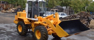
Amkodor TO-18B is a universal front loader manufactured in Belarus. The advantages of the technology lie in its proven technical solutions, as well as the possibility of modernization and updating by adding various options. Of course, you can choose them at your discretion, based on your needs and field of activity. Amkodor TO-18B is designed for unlimited use, and this can be confirmed by the adaptation of the loader to severe loads and extreme climatic conditions. Good handling and maneuverability, high load capacity and other important characteristics presented in this article are some of the main incentives for purchasing this loader. The material also discusses its cost and operating features.
Purpose
Amkodor TO-18b is designed for work in agricultural conditions, as well as in construction and public utilities. The machine is suitable for road installation work - for example, for patching highways and pedestrian streets, as well as cutting joints after the end of winter. The main purpose of the vehicle is, of course, the transportation of cargo containers; fortunately, the model in question has a good carrying capacity specifically for this purpose. In addition, the model’s capabilities are in demand in earthmoving operations, when working with fibrous materials and fragile loads. The equipment is in high demand in warehouses, retail warehouses, industrial areas, etc. The machine is also in demand in more complex operations performed at height, and in this case it can even replace a crane. All these and many other jobs are possible thanks to the support of a wide range of attachments.
Attachments
- A snow blade is a multifunctional tool with extensive capabilities, designed for removing compacted, dry and wet snow. In general, the blade copes with any snowdrifts, but the option may vary depending on the modification. For example, the version with a mechanical blade allows you to manually adjust the angle of inclination, and to do this you need to get out of the cab. The modification with a hydraulic drive is convenient in that it is adjusted using a lever directly from the cabin.
- Pallet forks are a device with the capabilities of a forklift, designed for loading and moving cargo containers that are easily deformed. This can be any fragile and easily breakable cargo, in particular glass containers. It is customary to place such cargo exclusively on pallets for safety reasons during transportation.
- A telescopic boom is a device with universal capabilities, capable of moving cargo in the air, lifting cargo containers to a certain height, and placing it, for example, on a high rack or shelf. The boom has a crane hook mounted on a hinged support, which allows the hook to rotate in any plane.
- A log grabber with a lifting capacity of 5 tons, designed for working with logs, pipes and poles. Cargo containers like this are captured using a clamp and do not fall out during transportation. The log grabber has unique hydraulic hoses, thanks to which the attachment does not experience any overload even at critically high pressure in the hydraulic system.
- Grab forks are a type of the above equipment, designed for work in enterprises involved in the production, recycling and storage of pipes with a small thickness (up to 400 mm in diameter). This is a convenient and useful option for industry.
- Snow bucket - this device is designed for cleaning, loading and transporting snow and other bulk materials, including construction waste, stones, soil, etc. In fact, this option is an alternative to a conventional frontal bucket. The difference lies in the material of manufacture - for example, a special thick steel is used for the snow removal bucket, which is not subject to corrosion or any damage.
- A bulldozer blade is a convenient device that can replace an expensive specialized bulldozer. This option has a rotary function, which is adjusted automatically using a lever from inside the cabin. The bulldozer blade is designed to reduce the cost of excavation work. From an economic point of view, this option looks more preferable than a special bulldozer.
- A jaw bucket is a device with two “jaws”, which are a double structure that interlocks with each other in order to tightly compress and hold the cargo container during its transportation. We are talking about mainly bulk cargo - sand, snow, garbage, leaves, etc.
- A brush is a utility attachment, the useful properties of which include the effective removal of snow, dust, soil and leaves - from roads, driveways, parking areas, as well as in warehouses, etc. The brush is perhaps the most popular option among representatives of housing and communal services.
- Forks with clamping/grabbing are a convenient device for working with fibrous loads, as well as a maximum density of 800 kg per 1 cubic meter. m. This includes loosened silage, hay, cut grass and other similar materials that are held by a clamp or grip during transportation.
- The cradle is a special lifting structure that can replace a crane. Used for working at heights. The operating principle of the cradle is as follows: the operator enters the “cabin” of the cradle, rises to a certain height and performs various tasks. For example, this could be finishing ceilings and high walls, finishing the facades of buildings and structures. In addition, the cradle is designed to facilitate work related to the installation and laying of high-voltage poles and lighting shades.
- An adapter is a device that you cannot do without when connecting heavy attachments. The adapter improves the reliability of fastening of such options, which have an extremely high load capacity. This could be a snow shovel, a cradle or a bulldozer blade.
- Bucket/blade blade - this device is designed to make working with icy snowdrifts easier. The bucket is installed on the edges of the bucket or blade, after which you can immediately get to work. The device is quickly removed and put on.
4.2 Controls of the Amkodor 342 (TO-28A) loader
To ensure the movement and operation of the loader, controls are located in the cab. The location and purpose of the control levers and pedals are shown in Figure 4.2. The position of the controls and settings after preparing the product for operation and before turning it on are described below in the section “Using the product in operation.”
Figure 4.2 — Location of control levers and pedals 1 — gear lever;
2 — reverse lever; 3 — steering wheel; 4 — multifunction switch; 5 — bucket control lever; 6 - boom control lever; 7 — reverse-acting brake valve; 8 — brake and neutral pedal; 9 — brake pedal; 10 — gas pedal; 11 — lever for manual control of fuel supply; 12 - range shift lever; 13 — rear axle engagement lever Steering column
Adjusting the tilt of the steering column The tilt of the steering column changes in steps from 25° to 40° with an interval of 5°. To change the tilt of the steering column, pull the handle towards you and tilt the column along with the steering wheel to the desired position. Release the handle and slightly rotate the column to the locked position.
| > | Adjusting the steering wheel height To set the steering wheel to the required height position, you must perform the following operations: - remove cap 2 on the steering wheel; — unscrew lock 1 by 3-5 turns; — set the wheel to the required height position; — tighten the clamp manually; — put the cap back in place. ATTENTION! The position of the steering wheel can vary in height within 100 mm. |
| Parking brake | |
| The parking brake is used to brake the loader when parked, hold it on a slope or rise, and also for an emergency stop if the wheel brakes fail. The parking brake is controlled by a tap installed in a bracket on the left wall of the cabinet. To turn on, turn the lever back to the fixed position. ATTENTION! Do not apply the brake while the forklift is moving. | |
| Air brake control The right pedal 9 (Fig. 4.2) is used for braking in transport mode, the left pedal 8 is for braking in work mode. The pedals are mounted in such a way that when you press the left pedal in operating mode, the right pedal is activated and the brake valve and GMT neutral are turned on. This allows increased activation of the hydraulic system. As long as the pedal is pressed, the diesel power will be used for the hydraulic system of the loading equipment. When you press the right pedal in transport mode, only the brake is activated through the rods without affecting the GMF, since the left pedal remains stationary. |
| Changing gears To engage a gear, shift the lever from neutral forward or backward - 1st, 3rd or 2nd, 4th gears will be engaged depending on the selected range. The lever is in the forward position - 1st gear in the working range or 3rd gear in the transport range will be engaged. The lever is in the rear position - 2nd gear in the working range or 4th gear in the transport range will be engaged. |
| Turning on the reverse The reverse lever is used to change the direction of movement of the loader. When you move the lever forward, the loader moves forward, and when you move it backward, it moves backward. ATTENTION! Driving with reverse engaged is possible only when the gear is engaged, and engaging any gear cannot change the direction of movement selected by reverse. Reverse movement is independent of the selected gear. |
| Switching ranges When moving the range lever forward, we obtain a working speed range. If you move the gear lever forward, we turn on speed I (working), and when moving it back, we turn on speed II. When moving the range lever back, we get the transport speed range. If you move the gear lever forward, we turn on III (transport) speed, and when moving it back, we turn on IV. Warning: Do not turn on the ranges while moving! ATTENTION! Within each range, start moving the loader only from the lowest gear (I or III). ATTENTION! In the middle position of the lever, the transmission is turned off. |
| Turning on the rear axle To reduce tire wear and save fuel, it is recommended to turn off the rear axle in the transport range in good road conditions. Engage the rear axle drive only when driving off-road or when the wheels of the front axle are slipping, as well as in operating mode. Move the rear axle engagement lever forward to disengage the rear axle, or backward to enable it. |
| ATTENTION! Engage and disengage the rear axle only when the loader is stopped. | |||
| Multifunction switch Provides turning on the direction indicators, switching the high/low beam headlights, high beam signaling, and turning on the sound signal. | |||
| The direction indicators turn on when the lever is pressed from the middle position forward or backward. The sound signal is activated when the lever is pressed in the axial direction. Turns on in any position of the switch lever. Switching the high/low beam headlights (after first pressing key 20, Fig. 4.1 - low beam is on) is carried out by moving the lever up/down. High beam - lower fixed position, low beam - middle fixed position, high beam flashing - when moving the lever all the way up from the middle position (non-fixed position). | |||
| Diesel stop handle To stop the diesel engine, pull the handle up. Hold the handle until the diesel engine comes to a complete stop. | |||
| Manual fuel supply lever The lever is used to select the required fuel supply (diesel speed). To increase the engine speed, move the lever forward, to decrease it, move it backward. In order to stop the diesel engine, perform the following operations: - use the manual fuel supply lever to first set the average and then the minimum idle speed; — after 3-5 minutes, pull the diesel stop handle up until it stops. | |||
| Fuel supply pedal When the pedal located under the driver’s right foot is pressed, the diesel fuel supply lever moves through a flexible cable. At the same time, the fuel pump rack moves, increasing or decreasing the fuel supply and engine speed. Return of the pedal to its original position is ensured by a spring. When you press the pedal, the engine speed increases, and when you release it, it decreases. | |
| — | Loading equipment control (Option 1) A-Boom control lever B-Bucket control lever. A-Boom control lever Boom Raise position. Move the lever back to raise the boom. Release the lever to stop the rise. Boom lower position - From the neutral position, move the lever forward (not all the way) to lower the boom. The released lever will return to the neutral position. ATTENTION! When the boom is lowered from the maximum dump height position to the digging position, the bucket automatically assumes that position. Boom holding position (neutral position). From the Raise or Lower position, the released lever will return to the neutral position. The boom will remain in the set position. Boom floating position - move the lever all the way forward. The lever position is fixed. The bucket descends to the ground and copies its profile. Do not move the lever to the float position to lower a loaded bucket. B-Bucket control lever Position - “Tilting”. Move the lever back to tilt the bucket. Position - “Hold”. Release the bucket control lever. The bucket will remain in the set position. |
| Position – “Unloading”. Move the lever forward to unload the bucket. Bulldozing cannot be carried out if the bucket is set to the “Unloading” position. Loading equipment control (Option 2) Bucket and boom control lever To move the bucket to the “Load” position, move the lever from the neutral position to the left. To move the bucket to the “Unload” position, move the lever from the neutral position to the right. Move the lever from neutral to the rear to raise the boom and forward to lower the boom. The boom will lower at the speed set by the pump. By moving the lever further forward, you will set the boom to the “Floating” position: the bucket will lower to the ground and copy the surface profile as it moves. If you move the lever from the Up, Down, Float, Tipping, Unload positions, it will automatically move to the neutral position. ATTENTION! Do not move the boom to the floating position when the bucket is loaded, as this may cause the bucket to fall. Important! When the bucket is lowered from the maximum dump height position, it automatically assumes the digging position. The speed of lowering/raising the boom and rotating the bucket can be adjusted using the manual fuel control lever and hydraulic control levers. | ||
| Instrument cluster Includes 4 instruments and 4 warning lamps. A - diesel oil pressure indicator; B - voltmeter; B — coolant temperature indicator; G - fuel level indicator; D — warning lamp for emergency reduction of oil pressure in the engine; E—battery discharge warning lamp; Ж - warning lamp for emergency increase in coolant temperature; 3 - low fuel level warning light. | ||
Diesel oil pressure indicator
Monitor the instrument readings while the diesel engine is running. The normal pressure of a heated diesel engine is 0.28 -0.35 MPa (yellow zone), when cold it is 0.6 MPa. ATTENTION! Do not allow the diesel engine to operate if the indicator needle is in the red zone. The red emergency lamp lights up when the oil pressure in the diesel engine is below the required level (0.08 MPa). The light also comes on when the diesel engine is not started and the ignition key is in the “I” position, indicating a lack of pressure. After starting the diesel engine, the light should go out; if this does not happen, it means the pressure is below the required level - stop the diesel engine. ATTENTION! It is allowed for the light to light up at minimum diesel speed.
The indicator scale has three zones: red zone - 0-0.1 MPa, yellow zone - 0.1 -0.5 MPa, green zone - 0.5 MPa and above.
Voltmeter
Shows the battery voltage when the starter switch key is in position 1. When the diesel engine is running, shows the voltage at the generator terminals.
If the arrow is in the green zone (26-30.5 V), the voltage is normal.
ATTENTION! When starting the diesel engine, the instrument needle may be in the red zone. The red warning lamp lights up when the battery is discharged, and the voltmeter needle is in the red zone - 18 - 26 V. Turn off the diesel engine and eliminate the cause.
ATTENTION! The light comes on when the ground switch is turned on. After starting the diesel engine, the light should go out.
The indicator scale has the following zones: red zone -18-26 V, yellow zone - 30.5-32 V, green zone - 26-30.5 V.
Coolant temperature gauge
The normal working zone of 75-95° corresponds to the green sector.
If the diesel engine overheats, eliminate one of the following possible causes:
— low coolant level;
— the fan belt is loose;
— the radiator shutter is closed;
| — the radiator is dirty. The red diesel overheating warning light lights up at a temperature of 104°C. Stop the diesel engine and find out the cause. The instrument scale has three zones: red zone - 40 and 105-120 ° C? yellow zone - 50-75°C and 100-105°C, green zone - 75-100°C. Fuel level indicator Indicates the approximate amount of fuel in the tank. Never work with an almost empty fuel tank to avoid air entering the fuel system. The red light next to the indicator lights up to warn you that the fuel level in the tank is low. The instrument scale has the following divisions: red - 0 - 1/4, yellow zone - 1/4 - 1/2, green zone - 1/ (full tank). Remote power switch button When you press the red button, the ground turns on, and when you press it again, it turns off. ATTENTION! It is possible to turn off the “mass” switch only when the diesel engine is switched off. Switching on and off is controlled by light bulb 25. ATTENTION! In the event of a short circuit in the circuit and if it is impossible to turn off the ground using the button on the instrument panel, open the rear hood grille and turn off the ground using the button located on the body of the ground switch. | ||
| Starting a diesel engine Start a diesel engine using the starter switch key, which has four positions: 0 - ignition is turned off (neutral position), the key is inserted and removed; I — ignition is on, non-locking position (the electrical system is turned on, all devices are functioning); On the oil pressure indicator, the emergency pressure indicator lamp II lights up - the starter is turned on, and after the diesel engine starts, the indicator lamp goes out. III - power supply for radio receiver, etc.; At ambient temperatures above +5°C, start the diesel engine in the following sequence: | ||
| 1) set the fuel supply control pedal to the maximum supply position (press all the way); 2) turn the starter switch key to position II; In this key position, the starter will start working. The duration of continuous operation of the starter should not exceed 15 s. If the diesel engine does not start working, try to start it a second time, repeating all operations. It is recommended to make no more than three starter activations in succession at intervals of at least 1-1.5 minutes. As soon as the diesel engine starts working, the starter should turn off automatically. When the air temperature is below +5 °C and it is difficult to start the diesel engine with a starter, it is necessary to use an aerosol starting device. Install an aerosol can with a flammable liquid in the fixture bracket. Turn on the button to open the valve of the aerosol device for 1-2 s. In this case, flammable liquid is injected into the diesel suction manifold. After this, start the diesel engine. Aerosol starting device 1711.3741 may not be installed on the loader. In this case, to start the diesel engine in winter, use a can of liquid to start the engines. Instructions for use are written on the can. |
| Hazard warning lights It is turned on by pressing the button (the turn signals begin to flash), the button backlight also flashes. When pressed again it turns off. Signal lamps Red emergency warning lamps and a buzzer turn on in the following cases: — a drop in oil pressure in the transmission; — drop in air pressure in the brake system; — increasing the coolant temperature; — drop in diesel oil pressure. |
| Warning lights (1) 1. Engage the parking brake. 2. Turns. 3. High beam headlights. 4. Air filter clogged. 5. Oil filter clogged. 6. Turning on the backup steering drive. | |
| Button for checking the functionality of the warning lamps (2) The following warning lamps light up when the button is pressed: - air cleaner clogged; — clogging of the hydraulic system filter; — pressure drop in the steering; — pressure drop in the gearbox lubrication system; — pressure drop in the brake system; — minimum fuel level; — high coolant temperature; — drop in diesel oil pressure. | |
| Torque Converter Oil Temperature Gauge Monitor the torque converter oil temperature readings during operation. Normal temperature is 60-100°C. ATTENTION! The forklift may only be operated for short periods of time if the oil temperature is below 45°C. ATTENTION! Operating the loader with the gear engaged and in stop mode can lead to rapid overheating of the oil above 100°C. It is strictly forbidden to work in this mode! | |
| Transmission oil pressure gauge This gauge shows the oil pressure in the main line of the friction clutches. Normal pressure is -1.45-1.6 MPa at nominal speed. If the pressure drops or the level exceeds 1.5-1.7 MPa, turn off the diesel engine and eliminate the cause. | |
| Pressure indicator in the brake system The brake system of the loader consists of two circuits: 1st circuit - front axle brakes; 2nd circuit - rear axle brakes. There are two pressure indicators for each circuit on the instrument panel. Each indicator has built-in brake pressure warning lights. They light up when the pressure drops below 0.45-0.55 MPa. | |
| ATTENTION! When the light comes on, stop the forklift and if pressure does not return, correct the problem. IMPORTANT! When the pressure in the brake system drops below 0.4 MPa, the parking brake is activated. On the Amkodor-342V model, the light in the brake hydraulic system lights up when the pressure rises above 5.0 MPa. | |
| Electrical circuit fuses There are three fuse blocks: 1 - on the left side of the instrument panel; 2 - on the right side of the instrument panel; 3 - on the cabin ceiling. | |
| Fuse box type | Fuse type and rating | Location of the fuse box and name of the protected circuit |
| Block Pr 112 1x16A+9x7.5A | Pr112-3722200A 16A PrP2-3722100A 8A 16A 8A 8A 8A 8A 8A 8A 8A 8A 8A | On the left of the instrument panel Sound signals Not used (reserve) Direction indicators Emergency stop Right low beam Left low beam Right high beam Left high beam Right side light Left side light |
| Block Pr 112 1x16A+9x8A | PrP2-3722200A 16A Pr 112-3722100A 8A 16A 8A 8A 8A 8A 8A 8A 8A 8A 8A | On the right side of the instrument panel Auxiliary socket Indicator lights and instruments Not used (reserve) Brake light Cold start control Engine compartment lamps Rear work lights Reverse signal and light Not used (reserve) Rear fog lights |
| Block BP-1 5x7.5A+1x15A | 7.5A 7.5A 7.5A 7.5A 15A 7?5A | On the upper instrument panel Front work lights Switch illumination Windshield wiper Windshield washer and rear window washer Heater fan Courtesy lamp, fan and rotating light |
| Block 11.3722 | 2×60 A 60 A 60 A | On the electrical panel at the back under the hood of the car Reserve Battery charging circuit |
| Mounted fuse PR118B-01 | 2 A | Hangs on a harness near the generator Protects the generator diodes |
| To replace fuses, remove the block covers. In addition, a 2x60A power fuse block and a 60A mounted fuse are installed in the battery charging circuit under the engine hood. |
| Instrument lighting control When you turn the knob clockwise, the lighting is brighter; when you turn it counterclockwise, it is darker. The dashboard provides space for: A - control lamp for preheater operation at low temperatures; B — control lamp for operation of the heater recirculation pump; B - key switch for starting the engine heater at low temperatures. Aerosol switch for starting the engine at low temperatures When you press the button, the solenoid valve is activated to inject flammable liquid into the diesel intake manifold. The volume of the mixture depends on how long the button is pressed. Release the button to turn off the device. |
| / | Rear work light switch Press the key switch to turn on the rear work lights. Light switch / The key switch has 3 positions: - off; — side lights, instrument and license plate lighting are on; — still the same and the headlights ATTENTION! To switch on positions 2 and 3, press the key switch once (position 2) and again (position 3). |
| Lighting in the cabin The cabin light is located on the ceiling and is turned on by a lever on the left side surface of the light. | ■ |
| Sun visor Mounted on the upper dashboard and can be adjusted to the desired angle. | |
| Auxiliary Outlet Located on the right side of the steering column and used to turn on a portable lamp. | |
| Seat The cabin has a soft sprung seat. The seat has adjustments: height (80 mm), driver weight (60-120 kg), longitudinal direction (160 mm), seat back angle (5-25°). The seat is equipped | |
| knots for fastening the seat belt. 1 — handle for adjusting the seat depending on the driver’s weight; 2 — handle for adjusting the seat in the longitudinal direction; 3 — backrest tilt adjustment handle. | |
| Adjustment of the seat in the longitudinal direction is carried out by pressing handle 2 to the right, as a result of which the latch is released and the cushions can move back and forth relative to the control levers in the cabin. After completing the adjustment, release the handle. The seat is adjusted depending on the driver’s weight by rotating handle 1 clockwise or counterclockwise. | |
| The backrest tilt is adjusted using handle 3. The handle is loosened by rotating counterclockwise, and the backrest is set to the required position steplessly, after which the handle is clamped and fixes the backrest in this position. The seat height adjustment has four fixed positions. For the required position, you need to hold the bottom of the seat cushion with both hands and pull it up until it clicks. Consistently moving to the next fixed position, the required height is selected. To lower the seat to its lowest position, you need to pull the seat all the way up and release, as a result the seat will take the lowest position. | |
| — | Heater recirculation dampers Serve to direct the warm air flow to the desired part of the cabin. |
| Heater valve Installed at the rear of the cab, behind the seat. To open, turn clockwise, to close, turn counterclockwise. ATTENTION!When draining and filling coolant, open the tap. Place for installing a fire extinguisher | |
| Cabin opening handle To open the cab door, pull handle 1 towards you. Locking the cab Both cab doors can be locked and locked from the cab. To lock the door, move lever 2 up. In this case, the cabin can be opened from the outside with a key. To open the door, you need to move lever 2 down and pull handle 1 back. The left door is equipped with a lock. | l |
| Upper instrument panel A - The front wiper switch has 3 positions: - off, - slow, - fast. If the forklift is equipped with a single-speed wiper, there is no “slow” position. When the windshield wiper is turned off, the blade automatically returns to its extreme position. | |
| B — Front window washer switch. B — The rear wiper switch has 2 positions: — off, — fast. | |
If the forklift is equipped with a single-speed wiper, there is no “slow” position. When the windshield wiper is turned off, the blade automatically returns to the neutral position. G - Switch for front working lights. Press the key switch to turn on the front work lights. D - Flashing light switch. Press the key switch to turn on the flashing light. E - Cabin fan switch. Press the key switch to turn on the fan.
F - Heater switch.
Press the key switch to activate the heater fan. The switch has 3 positions:
- switched off,
- low speed,
- high speed.
When the tap is closed, the heater fan operates like a regular cabin fan.
| Door release device Used to release a door locked in the open position and prevent accidental closing (slamming) of the door during braking. To release it, pull the lever back. |
| Do not work with open doors without securing the doors. |
| Hammer On the rear wall of the cab, to the left of the operator, there is a hammer that is used in case of an accident when the door does not open. In this case, break the glass with a hammer. |
| Fan The fan is located on the upper instrument panel and serves to create excess pressure in the cabin. The direction of air flow can be changed using a hinged bracket. | ||
| Exterior mirrors To improve visibility, there are two exterior mirrors on brackets and one mirror in the cab. Mirrors are adjustable. Bracket for installing a mirror in the cabin | — | |
| Tail lights The rear lights have two positions - working (vertical) and transport (horizontal). To transfer the lights from the working position to the transport position, you must perform the following operations: - pull the light housing in the direction indicated by the arrow and turn the housing to a horizontal position, | ||
| — the flashlight housing will lock automatically. |
| Retroreflector installation locations |
contents .. 11 12 ..
Features of the device and operation
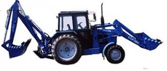
- TO-18B is a single-bucket front loader with a number of features that set it apart from its closest competitors. The machine is endowed with excellent maneuverability, controllability, efficiency and efficiency. The loader uses an articulated frame and hydraulically assisted steering. Of course, this only had a positive effect on the maneuverability of the loader. This feature made it possible to operate the device in hard-to-reach areas, in the presence of obstacles, as well as in cases where the vehicle needs to turn around in cramped conditions. When performing sharp maneuvers, rolls and vibrations are eliminated - thanks to the ideal center-to-axle weight distribution and, importantly, a low center of gravity. In addition, let’s also pay attention to the excellent off-road component of the TO-18B loader. We are talking about large wheels made of thick and wide-profile rubber, which is almost impossible to puncture. High ground clearance, wide track and minimal body overhangs also allow you to overcome serious off-road conditions - muddy soil, hills and ruts.
- The factory engine D-442MSI with a power of 130 horsepower is responsible for performance. The more affordable version received a 123-horsepower D-260.2 unit. Both engines have good traction characteristics, due to the slight difference in power. Both engines unleash the full potential of the loader and its attachments. The pre-heating system and liquid cooling contribute to better ventilation of internal combustion engine components, as well as uninterrupted engine operation at any time of the year. Due to this, the motor is well adapted to frost and hot conditions. In addition, the power plant allows you to reach a maximum speed of up to 36 km/h, which is very important when driving in the city. Good dynamics and good fuel efficiency allow you to cover long distances in a fairly short time.
- The hydraulic system design includes two separate pumps. Pressure is supplied to the steering, as well as the hydraulic distributor. The gearbox is hydromechanical with two forward and two reverse gears. High hydraulic power allows you to work with heavy loads, and at the same time you do not have to worry about overloading and overheating of the working body.
- The TO-18B front loader bucket has a nominal capacity of 1.9 cubic meters, and the maximum load capacity reaches 3400 kg. The breaking force is 10500 kg. This great value was achieved thanks to the Z-shaped design of the attachment (bucket).
- The loader under consideration is at the level of more expensive foreign analogues in terms of comfort in the cabin. Thus, the Belarusian-made model has a high level of ergonomics in the arrangement of working parts, switches, buttons and levers. For example, the controls for attachments are located on a separate joystick, located at hand. In general, all controls are as close as possible to the driver. This also applies to control and measuring instruments, which display important information about the condition of the working parts, their load and possible overload. In addition, the developers paid special attention to the organization of the driver’s workplace - due to the ability to adjust the seat and steering column. Also worthy of special attention is the wide glass area, without which there would be problems with visibility. Moreover, the glazing had to be slightly tinted to prevent ultraviolet rays from entering the cabin - this feature of the glass can be appreciated in hot sunny conditions. The loader has a full electrical package, including a heated seat and a full heating system. An air conditioning system can be ordered as an option. The noise insulation of the loader interior is at a high level, as befits models of this class. The cozy atmosphere in the cabin, the presence of pleasant-to-touch plastics, the successful layout of the driver’s seat and other features – all of this together had a positive effect on labor productivity. The driver is less distracted and is able to work longer, which is very important during multi-shift work.
- The TO-18 B front loader is easy to maintain and long-term use. As confirmation of this, we note the high maintainability of the machine, the reasonable cost of components and consumables, as well as the durability of the most expensive components, assemblies and working parts of the machine. Convenient access to the engine compartment, due to the hood cover with gas-filled supports, makes it easy to get the necessary components that need to be replaced. The entire maintenance process does not take much time, especially when replacing consumables.
Advantages and disadvantages
Of course, the popular model has both advantages and disadvantages. The advantages include:
- Reliability of the design.
- Ease of maintenance.
- Availability of spare parts.
- Low cost of the loader compared to competing models.
- High performance.
The main disadvantage is the poor security of the units. The working rods of hydraulic cylinders do not have reliable devices that protect them from dirt and dust. Open hoses are also susceptible to damage.
Specifications
- Load capacity/total weight – 3400/11900 kg
- Engine – D442MSI
- ICE parameters: diesel, 130 l. With.
- Transmission – four-speed, manual
- Speed – 40 km/h (maximum)
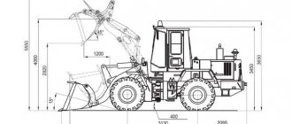
- Dimensions, mm: Length – 7100, Width – 2500, Height – 3350
- Reach of the edge of the working unit - – 900 mm
- Service brake parameters - multi-disc oil bath brakes
- Parking Brake Options - Single Disc Dry Brakes
- Fuel tank capacity – 215 l
- Hydraulic tank capacity – 110 l
- Unloading height/breakout force – 2800 mm/103 kN
- Tire parameters – 21-24
- Front track – 1930 mm
- Rear track – 1930 mm
- Width of outer turning radius – 5600 mm
- Working body – bucket
- Bucket volume – 1.9 cubic meters. m.
- Bucket cutting edge width – 2500 mm
- Wheeled chassis - yes.