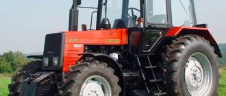
The MTZ 892 tractor produced by the Minsk Tractor Plant is a modification of the legendary version MTZ 82, which has been produced since 1974. The technical characteristics of the MTZ 892 included in the design make it possible to use it not only in agriculture, but also in other industries where there is a need to use universal vehicles with increased cross-country ability.
The Belarus 892 MTZ differs from the base model in the following parameters: the presence of a turbocharged engine with an intercooler, which increases the torque of the power unit by 30%, an installed MTZ synchronized gearbox, and an increased standard size of standard tires.
MTZ 892 is a wheeled universal row crop agricultural unit with all-wheel drive, which is classified with traction class 1.4. The main purpose of Belarus 892 is to perform a large number of different agricultural works, from preparing the soil for sowing to harvesting and transport operations.
However, unlike the power-armed tractor MTZ 3022, it is not intended for cultivating large areas of land. In addition, as already noted, MTZ 892 can be used in public utilities and forestry, industry and construction.
The design of the gearbox installed on the MTZ 892 provides a multiplier (overdrive gear), which provides 18 forward gears and 4 for reverse gears. The Minsk Plant also produces a modification of the MTZ 892.2 tractor. The main technical difference between this model and the MTZ 892 is the installation of a reinforced beam-type front drive axle.
Meet Belarus 892 MTZ
The MTZ 892 wheeled tractor is an economical model of equipment. This is a modification of the MTZ 82, the most popular series of multi-purpose off-road wheeled vehicles. Among wheeled tractors, only the MTZ 3022 is second in terms of power output.
The technical characteristics of MTZ 892 are as follows:
Dimensions MTZ 892
- Traction class – 1,4.
- Diesel engine power – 66 kW.
- Torque at peak load – 395 N/m.
- Torque reserve factor — 15%.
- Fuel consumption when boosting is no more than 14 liters per hour.
- Wheel layout – 4x4.
- Ground clearance - 0.65 m.
- Speed limits are 39.5–2.2 km/h.
Thanks to the large number of attachments, all-wheel drive agricultural implements are in demand in construction, forestry, and transportation. Medium-power equipment, due to its efficiency and versatility of use, has found favor in small businesses.
The cost of MTZ 892 from official dealers is comparable to a middle-class passenger car. Additional equipment and ease of installation turn universal, diverse equipment into a specialized center with instant reorientation of the direction of activity.
Technical characteristics of MTZ 892
Features of operation
The tractor uses a hydraulic system and operates using attachments located at the rear and front.
For high-quality operation of the equipment, you need to monitor and add hydraulic fluid, carry out timely maintenance and ensure that all rubbing parts are lubricated.
Transmission oil must be used for MTZ. They change it every 60 thousand kilometers, regardless of wear of parts.
If the machine operates in hot summers, then choose 140 SAE class oil; if the climate is moderate, then 90 SAE. For economy, you can use multi-grade oil.
The fuel used is diesel, double purified.
However, there are complaints that when using a three-furrow plow, hard soil is plowed unevenly, this is due to the fact that the diesel engine power is not enough to produce high-quality work.
Also, for this reason, at maximum load the front loader malfunctions.
Run-in
Estimated break-in time is 30 hours. During the procedure, all parts and assemblies are broken in and, therefore, the service life of the unit increases.
The sequence of actions plays an important role.
Experts recommend operating the tractor for the first half of the time without using attachments at half the power, and for the remaining time using the hydraulic system, slightly increasing the load.
Important! Do not overload the motor.
After completing the tractor run-in, you must perform the following steps:
- Warm up the engine and tighten all fasteners, as well as adjust the valve clearances.
- Drain the oil, first turning off the engine and the rear power take-off shaft drive.
- Wash all plugs and filters with diesel fuel.
- Fill with fresh oil and lubricate all tractor components. More details about this procedure and its sequence can be found in the user manual.
- Check all tractor tanks for leaks.
- Adjust the bearings and tighten the wheel mounts.
Malfunctions
| The engine does not start: | lack of fuel or engine oil; Dirt has entered the fuel or air filter; The ignition system is broken. |
| The tractor vibrates: | insufficient fuel level; weak bolt tightening; incorrect installation of attachments. |
| Gearbox malfunctions: | unadjusted clutch; increased or decreased pressure in the hydraulic system; lack of oil. |
Power equipment MTZ 892
Design of the D-245 diesel power system
The MTZ 892 engine with a volume of 4.75 liters is produced at OJSC MTZ. The four-cylinder power plant with direct fuel injection D-245.5 is equipped with a turbocharger and intercooler. Motor cooling is water. Rotation speed - 1.8 thousand revolutions. The guaranteed service life of the diesel engine is 5 thousand hours. The fuel tank is designed for 10 hours of continuous operation without refueling.
Starting the engine in sub-zero temperatures is facilitated by the electric torch heating option. An electric starter with a power of 6 kW operates at a voltage of 24 V. In extreme cold weather, the starter is helped by the ignition impulse of the aerosol inside the cylinder ⌀ 110 mm. The equipment is adapted for boxless all-season maintenance in Arctic conditions.
Branded service centers for the repair and maintenance of MTZ 892 tractors are present in regional centers of the Russian Federation. The supply of repair kits, individual parts and assemblies is simplified due to close economic ties between the republics.
Load capacity, size and weight
When working with a 110 mm cylinder, the load capacity is 3000 kgf, for 115 mm, respectively, 4000 kgf. In this case, the maximum pressure will be 200 kgf/cm.
The pump capacity is 45 l/min with a hydraulic system capacity of 21 l.
The total length of the MTZ-892 is 3,970 mm on a wheelbase of 2,460 mm. At the same time, the width of the structure will be 1,970 mm. The cabin height of this tractor is 2,820 mm. The machine leaves a track of 1,470-1,650 mm with the front wheels, 1,830-2,150 mm with the rear wheels.
The ground clearance that characterizes this technique is 640 mm under the front axle and 465 mm under the rear. The turning radius of this model is 4.3 m.
Attention! If there is a need to ford, then the maximum water level can be 0.8 m. Weight for operation excluding ballast will be 3,900 kg.
If the MTZ-892 tractor is equipped with standard tires, then their size for the front wheels is 13.6R20, for the rear wheels – 18.4R38. Due to the fact that this vehicle has a 4x4 wheelbase, the model has great cross-country ability.
This fact allows you to use the tractor where there is no hard road surface. To make moving through particularly difficult areas easy, the front portal axle has a differential lock.
If necessary, this device turns on automatically, which reduces the risk of slipping.
Transmission and chassis
The MTZ 892 gearbox is synchronized. The multiplier installed in the gearbox provides additional acceleration when moving. Variability of speed selection: 18 frontal gears during idle and working, 4 when reversing.
Speed ratio with the acceleration gearbox turned on (doubling the number of speeds):
- Forward movement – 39.5–2.5 km/h.
- Reverse movement – 5.5–9.2 km/h.
Diagram of the MTZ 892 gearbox with an overdrive gearbox
With multiplier disabled:
- Forward – 2.2–27.5 km/h.
- Backward – 4.2–7.5 km/h.
In the event of a sudden change in load towards an increase, the tractor will not stall due to the possibility of self-locking the differential of the front drive axle portal. Slipping of the rear wheels initiates self-activation of the differential in automatic mode. Synchronizing the load on the rear wheels increases the stability and maneuverability of the tractor.
Front non-driving axle of tractors of the MTZ family
Transmission of the MTZ 892 tractor:
- The gearbox is mechanical, with a doubler gearbox.
- The clutch is single-plate, dry.
- The brake system is disc, dry, interlocked with the pneumatic braking system for trailers. The parking brake disengages the transmission.
- The power take-off shaft is two-speed, independent, controlled by a hydromechanical system.
Specifications
Technical characteristics and design properties provide functionality and versatility. The characteristics have the following parameters (except for the parameters of the already specified units):
- Overall dimensions: Base – 2.44 m.
- Length – 3.97 m.
- Width – 1.97 m.
- Height – 2.85 m.
- Weight – 3.90 t.
- The smallest forward is 2.10 km/h.
Steering of MTZ tractors
Hydrostatic steering is fed by a metering pump. The hydraulic cylinder is located in the steering linkage. The hydromechanical booster makes it easier to control equipment on rough terrain, in off-road conditions and under maximum traction loads of mounted and towed devices.
Steering gear drive for tractors of the MTZ family
Tractor driver's workplace
The Belarus cabin is designed according to European standards of comfort. All-round view. Heating system. Forced ventilation with air filtration. Windshield wipers with washer on the front and rear windows. The operator's seat position is adjustable vertically and horizontally. The position of the steering column is adjusted. Emergency dismantling of the cabin is provided. The side windows slide. The ceiling hatch opens.
Layout of controls in the cab of the MTZ 892 tractor
Mechanical transmission unit
The mechanical gear unit of the gearbox consists of primary 34a and secondary 6 shafts coaxial with each other, located in the gearbox housing 29 (Figure 3.3.1), as well as an intermediate shaft 32 and a 1st gear and reverse shaft 27 parallel to them (Figure 3.3.2) .
The primary shaft 34a (Figure 3.3.1) is mounted on two ball bearings. One of the bearings is placed in a cup 36a, which is installed in the bore of the front wall of the gearbox housing 29 and is attached to it with bolts. The second is at the bore of the secondary shaft 6. The driven gear of the reduction gearbox 35a is fixedly mounted on the splines of the front console of the primary shaft. In the span between the supports of the input shaft there are installed a double-crown drive gear of the 4th and 5th gears 1 and a drive gear of the 3rd and 6th gears 5, which are able to slide along the axis of the shaft along its splines.
The design of the front part of the input shaft of the gearbox of 9F/9R tractors equipped with a reverse gearbox is shown in Figure 3.3.2. It has the following differences compared to the 9F/2R gearbox discussed above with a mechanical overdrive gearbox (Figure 3.3.1).
The driven gear of the reverse gearbox 35b (Figure 3.3.1) is installed on the smooth neck of the front console of the input shaft of the gearbox 34b and has the ability to rotate freely on a roller bearing. Gear 34b is in constant mesh with the large rim of the intermediate gear of the gearbox 31.
A synchronizer 38 is installed in front of the driven gear of the reverse gear 35b, the movable carriage of which is always connected to the input shaft of the gearbox 34b through a splined sleeve 37 fixedly mounted on it. To control the synchronizer, a fork 39 is used, into the groove of which the disk of the synchronizer hub 38 fits.
The fork 39 with the roller has the possibility of axial movement in the hole of the cup 36b of the input shaft. On the roller 39 there are two transverse holes into which the spring-loaded ball of the latch 40 fits. The holes provide the roller 39 and the fork associated with it with two fixed positions.
The secondary shaft 6 is supported by two tapered roller bearings, one of which is located in the bore of the gearbox housing 29, and the second in a cup 16, which is installed in the bore of the rear wall of the gearbox housing 29 and is attached to it with bolts. Structurally, the secondary shaft is made integral with the driven gear of the first stage of the range reducer. The gear ring of the gear is located cantilevered in the front part of the secondary shaft 6. In the span between the supports of the secondary shaft, the driven gear of the second stage of the range gearbox 18 is mounted motionless on the splines, which is also the drive gear of the synchronous drive of the rear PTO. On the rear console of the secondary shaft, drive gear 17 of the main transmission of the rear axle (small bevel gear) is mounted motionless on splines.
In the front part of the hollow intermediate shaft 32, a double-crown driven gear for the 5th and 8th gears and reverse gears 28, a driven gear for the 4th and 7th gears 27, and a driven gear for the 3rd and 6th are fixedly mounted on its splines -th gear 26, on the hub of which the double-crown intermediate gear 25 rotates freely on a needle roller bearing. Gear 25 is in constant engagement with gear 25 (Figure 3.3.2), providing the ability to engage low gears and reverse gears through gear 26 , as well as the GCU drive. In the rear part of the intermediate shaft 32 (Figure 3.3.1), a sliding gear 23 is installed on its splines - the drive gear of the first stage of the range reducer.
The front support of the intermediate shaft 32 is a ball bearing located in the cup 33 of the front wall of the gearbox housing 29. The rear support of the intermediate shaft is a bronze bushing installed in the bore of the drive gear 23 of the second stage of the range reducer.
The drive gear of the second stage of the range gearbox 23 rotates freely on two roller bearings located in the cup 22, installed in the bore of the rear wall of the gearbox housing 29 and bolted to it. Gear 23 has external and internal toothed rims, as well as cams located at its rear end, which serve to drive the synchronous rear PTO. In the bore of gear 23, a pin is attached to a socket 20 with a bronze bushing, which is a support for the internal shaft 19. Outside, an impeller 21 is fixed to the gear 23, which, through intensive splashing, improves the lubrication of the main transmission gears and the differential of the rear axle of the tractor.
Shaft supports for 1st gear and reverse gear 27 (Figure 3.3.2) – two ball bearings located in the bores of the gearbox housing. In the front part of shaft 27, a sliding gear 26 is installed on splines - a gear for low gears and reverse gears. Moving the sliding gear 26 back until it engages with gear 27 (Figure 3.3.1) allows you to obtain lower forward gears, and moving it forward allows you to obtain reverse gears. In the latter case, gear 26 (Figure 3.3.2) meshes with the reverse intermediate gear 15, which is mounted on axis 14 and rotates freely on it on a needle roller bearing.
91
1 – drive gear of 4th and 5th gears; 2 – 4th and 5th gear fork; 3 – fork body; 4 – fork for 3rd and 6th gears; 5 – drive gear of the 3rd and 6th gears; 6 – secondary shaft with driven gear of the 1st stage of the range reducer; 7 – adjusting shims; 8 – gearbox control lever; 9 – gear fork; 10 – filler plug; 11 – roller; 12 – adjusting shims; 13 – diesel start blocking sensor; 14 – limit plate; 15 – gearbox control cover; 16 – glass; 17 – drive gear of the main transmission of the rear axle; 18 – driven gear of the second stage of the range reducer; 19 – internal shaft; 20 – socket with a bronze bushing; 21 – impeller; 22 – glass; 23 – drive gear of the first stage of the range reducer; 24 – drive gear of the first stage of the range reducer; 25 – intermediate gear; 26 – driven gear of 3rd and 6th gears; 27 – driven gear of the 4th and 7th gears; 28 – driven gear of the 5th and 8th gears and reverse gears; 29 – gearbox housing; 30 – nest; 31 – intermediate gear; 32 – intermediate shaft; 33 – glass; 34a and 34b – input shaft; 35a – driven gear of the reduction gearbox; 35b – driven gear of the reverse gearbox; 36a and 36b – glass; 37 – bushing; 38 – synchronizer; 39 – roller with fork; 40 – locking ball.
892-0000010B RE
Figure 3.3.1
Gear 15 is in constant mesh with the smaller ring gear of double-ring gear 28 (Figure 3.3.1).
If the tractor is equipped with a reverse gearbox (Figure 3.3.3), then the intermediate reverse gear 15 (Figure 3.3.2) is absent in the gearbox, and the reverse gear of the tractor is realized by turning on the reverse gearbox (see section 2).
In the rear part of the shaft 27, on its smooth neck, on a bronze bushing, a driven gear for low gears and reverse gear 25 is installed, which is in constant engagement with the smaller ring gear of gear 25 (Figure 3.3.1) of the intermediate shaft 32. If the tractor does not use a gas turbine (or is not equipped with a gas turbine unit), then through gear 25 (Figure 3.3.2) through gear 24 the drive of shaft 27 is provided. In this case, gear 24 is connected to the internal spline of gear 25 and to the outer spline of shaft 27, as shown in Figure 3.3.2. In a tractor equipped with a gas turbine unit, the spring ring 23 is moved all the way back, and when working with the gas turbine unit turned on, rotation is transmitted from gear 25 (Figure 3.3.1) to gear 25 (Figure 3.3.2), which rotates on shaft 27, and gear 24 is disengaged from gear 25 by the GCU lever. In this case, the power flow, after transformation into the GCU, is transmitted to shaft 27 through its splined connection with gear 24.
On the right side of the gearbox, an axis 28 is installed in the bores of the gearbox housing, on which the FDA drive gear 29 rotates freely on two tapered roller bearings. The power flow to the FDA is taken from the driven gear of the first stage of the range reducer 6 (Figure 3.3.1), from which gear 29 (Figure 3.3.2) is in constant mesh.
On the front wall of the gearbox housing 29 (Figure 3.3.1), coaxially with the intermediate shaft 32, there is a socket 30, inside of which the front bearing of the internal shaft 19 is located, and outside are the ball bearings of the intermediate double-ring gear of the gearbox 31.
There are windows on the right and left of the gearbox body (Figure 3.3.2). The left window is closed by a cover 18, which contains an oil dipstick 19 for monitoring the oil level. If the tractor is equipped with a gas turbine unit or a semi-independent side PTO, then the cover 18 is dismantled and the window is closed with the housing of the gas turbine unit or semi-independent side PTO. In this case, oil level control is ensured by control plug 16.
The right window is covered by the FDA drive transfer case housing.
To drain the oil when replacing it, there is a hole in the lower part of the gearbox housing, closed with plug 17.
92
892-0000010B RE
93
1 – fork body; 2 – shaft; 3 – ball; 4 – gear lever; 5 – pipe; 6 – stopper; 7 – support; 8 – leash; 9 – gearbox control lever; 10 – retainer balls; 11 – locking strips; 12 – 4th and 5th gear fork; 13 – drive of the range reducer; 14 – axis of the reverse intermediate gear; 15 – reverse intermediate gear; 16 – control plug; 17 – drain plug; 18 – cover; 19 – oil dipstick; 20 – 1st gear and reverse fork; 21 - fork of 3rd and 6th gears; 22 – cover; 23 – spring ring; 24 – gear; 25 – driven gear for low gears and reverse gear; 26 – gear for low gears and reverse gears; 27 – shaft of 1st gear and reverse gear; 28 – FDA drive gear axis; 29 – FDA drive gear
Figure 3.3.2
Attachments
A universal tractor, in addition to cargo trailers and purely agricultural devices for tillage, sowing, and mowing, is capable of working as a lift and loader. Buckets up to 2 m3, transport forks, stackers, tilters, log grabbers - this is an incomplete list of mounted loading equipment.
MTZ 892 with loader and forks
Related video: Review of the MTZ-892 tractor
Publications on the topic
Characteristics of the mini-tractor Belarus 320.4
Review of Belarus mini-tractors of all models
Description of the technical characteristics of the MTZ 1523 tractor
Tractor cabin
For maximum operator safety, the manufacturer has equipped the cab with a ROPS system. The device of this design fully complies with OECD requirements.
To create the most comfortable working conditions, systems are installed in the cab to ensure a comfortable position and stay for the driver. Among them are filters that prevent dust and exhaust gases from entering the cabin.
Purified air is forced into the cabin using a fan. The heating system helps maintain a comfortable temperature in the cabin even in cold weather. The side windows are equipped with an opening system. The design also includes a rear window and a sunroof.
The glass is cleaned using electrical systems found in the front and rear windows. Washers are installed only at the front.
For various modifications, variations with a protective awning on a frame created on the basis of a standard cabin are possible.
In rooms with low ceilings this structure can be dismantled. The spacious dimensions of the cabin will provide comfort for operators of any height.
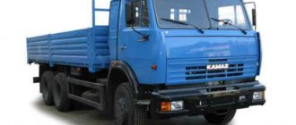
Find out the technical characteristics of KamAZ-65115 - a model that deserves special attention. In our article you can read reviews from experts about the operation of Shtil petrol trimmers.
This information: https://spez-tech.com/tehnika/gruzovie-avto/zil/130-harakteristiki-i-osobennosti-konstruktsii.html will help you understand the technical characteristics of the ZIL-130.