General - Electrical Diagram Gas 3309 Diesel
Controls and instruments of GAZ- 3. GAZ- 3. 30. 7. 5. CONTROLS AND INSTRUMENTS. The location of the controls for GAZ-3. GAZ-3. 30. 9 vehicles is shown in Fig. Controls. The lever has six fixed positions - I, II, III, IV, V and VI and four non-fixed positions “A” (Fig.
GAZ 3307, 3309 - electrical diagrams. Gasoline engine ZMZ 513. Diesel engine MMZ D-245.7 E2. The location of the controls for the GAZ-3307 and GAZ-3309 vehicles is shown in Fig. The gear shift diagram is shown in Fig. In the cabin of GAZ 3309.mp4. RomanFTr Test drive from Olga Guryeva. Alexander Gorelov 235,676. Cars GAZ-3309 Dobrynya Cars GAZ-3309 with a diesel engine. Instrument panel GAZ-3110 Electrical diagram of GAZ-3110 II - high speed windshield wiper is turned on, III - intermittent wiper operation is turned on.
- GAZ 3307, 3309 - electrical diagrams. Gasoline engine ZMZ 513. Category: Electrical circuits
- GAZ 3307-3309 electrical diagram. Author: Category: car manuals 03/15/2011 No comments. DOWNLOAD gas 3307-3309 electrical diagram.
- Electrical diagram of GAZ-3308, GAZ-3309 Euro 4 cars (EDC 17 ECU). Electrical diagram of the Volga with a Chrysler engine (GAZ 3102, GAZ 31105). Electrical diagram of Lada Priora.
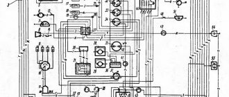
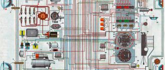
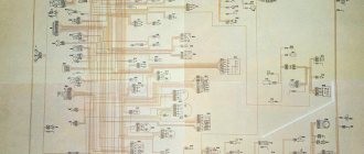
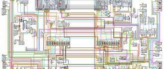
- On the left are usually the headlights and sidelights of the front of the car, to the right are the electrical equipment of the engine compartment, interior and rear lights. In particular, you can download a color electrical diagram. Electrical diagrams for gas 3307 and gas 3309.
- DOWNLOAD gas 3307-3309 electrical diagram.
- The location of the controls for the GAZ-3307 and GAZ-3309 vehicles is shown in Fig. The gear shift diagram is shown in Fig.
I — intermittent operation of the windshield wiper is on; II — low speed windshield wiper is on; III - high speed windshield wiper is on. Rice. Positions of the windshield wiper and washer switch lever (without sound signal)Fig. Positions of the windshield wiper and washer switch (with sound signal)*. If the switch has a horn switch (see A), and to turn on the horn, move the lever (from any position) towards you (in the direction of the arrow “B”).
Cars GAZ - 3309 Dobrynya Cars GAZ - 3309 with a diesel engine Dashboard GAZ-3110 Electrical diagram of the GAZ-3110. Finally, I have restored access to my account in depositfiles and now I can share the electrical diagram of the GAZ 3309. On the Internet, the same voluminous and I have never seen a colored one like this one, which was quite surprising. Electrical diagram of GAZ 3307. Anatoly, Euro-3 diesel, 3307 gasoline. Electrical circuit diagram Guide for repairing electrical equipment of family cars. This manual provides the technical characteristics of the GAZ-33081 vehicle with the D-245.7 diesel engine (D-245.7 E2). GAZ-3307 and GAZ-3309 are Soviet and Russian cars in the fourth family. Since 2012, a modification of the GAZ-33096 with a Cummins ISF 3.8L diesel engine, similar to that used on the truck, has been produced to order. Malfunctions of the electrical equipment of the legendary automobile GAZ 3307 and 3309. If you have an electrical diagram on hand, you can easily use it to determine a malfunction in the operation of a particular element.
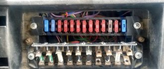
The windshield wiper only works when the ignition is on. On the inside of the panel there are signs indicating the consumers protected by these fuses.
Handle for the headlight range control unit. On some vehicles, the sound signal is turned on by the turn signal and headlight switch (see. At any intermediate position of the damper, a mixture of outside air and air from the cabin enters the heater. It turns on the supply of liquid from the engine cooling system to the cabin heater radiators. The gear shift diagram is shown in Fig. Gear shift diagram.
I — ignition is on (GAZ- 3. GAZ- 3. 30. 9). II - the ignition and starter are turned on (GAZ- 3. GAZ- 3. 30. 9). III - the ignition is turned off and, with the key removed, the anti-theft device is turned on (GAZ-3. GAZ-3. 30. 9). To avoid failure of the contact part of the instrument switch and starter, do not leave the key in an intermediate position.
Key positions of the ignition switch (instruments), starter and anti-theft device. GAZ-3. 30. 7) or fuel supply control pedal (GAZ-3. Hazard warning system switch button. Location of instruments of the GAZ-3 vehicle. Instrument panel of the GAZ-3 vehicle.
Lights up when the oil pressure is 4. Pa (0.4-0.8 kgf/cm. When you press the button, the indicator lamps of blocks 6, 7 and 8 light up if they are in good working order. When the ignition is turned on, it lights up when the brake fluid level in the master cylinder reservoir is below the “ mark MIN" or when the midnight brake is on.
Lights up when the coolant temperature is above 1. C. When the position is on, the light in the switch lights up (green filter). When the switch is in the on position, the light bulb (green filter) lights up.
Electric motors operate at maximum rotation speed when switches 1 are turned on simultaneously. When only one switch 1 is turned on.
By turning the central light switch knob clockwise, the intensity of the instrument lighting is adjusted. Positions of the central light switch knob. ABS. Constantly lights up when the remaining fuel in the tank is less than 1. Instrument panel of a GAZ-3 car. When you press buttons 1, the lamps of the right or left blocks light up if they are in good condition, except for the lamp pos.
I instrument key, starter and anti-theft device). Lights up when the coolant temperature is above 1. Lights up when the side lights are turned on.
Lights up when the generator is faulty. Lights up when a vacuum is reached in the inlet pipe of the intake pipe 6.3. Pa (6.50 mm under.
When the instruments are turned on, it lights up when the brake fluid level in the master cylinder reservoir is below the MIN mark. Electric motors operate at maximum rotation speed when switches 1 are turned on simultaneously. When only one switch 1 is turned on. Constantly lights up when the fuel remaining in the tank is less than 1.
Lights up when the oil pressure is 4. Pa (0.4-0.8 kgf/cm.
gymrusoft.fo.ru
Malfunctions of the ignition system of GAZ-3307
For example, let's find a fault in the ignition system, which is one of the most important in a car. Failure or poor performance of any of the elements is a serious problem, especially while traveling. The engine stalls or runs intermittently, it is advisable to quickly find and eliminate the cause.
First, make sure that the problem is in the ignition system (there may also be a fuel supply malfunction). Remove the wire from any spark plug and bring its end to ground at a distance of 6–9 mm. When the engine is cranked by the starter, a spark should appear. Be careful, the circuit is under high voltage; you should work with rubber gloves or use improvised objects that do not conduct current, for example, wooden ones, holding the wire with their help. If there is no spark, remove the central wire from the distributor cover and check it in the same way as a spark plug.
There is a spark - the problem is in the breaker-distributor (item 3), if not - let's continue the search. Make sure that current is supplied to the induction coil terminal (item 5). To do this, connect the clamps of the control light to the corresponding connector and ground: the light should light up (with the ignition on). Similarly, check the output of the switch (item 4) with the + sign. If there is current, connect a light bulb (with a power of no more than 3 W) to the short-circuit terminal and ground. It should flash when the starter is turned on. If this happens, the ignition coil is faulty.
If the light is on continuously or does not light up, the switch is faulty (unfortunately, a typical problem on the GAZ-3307).
If current is not supplied to the coil, we determine according to the diagram the next element in the circuit - the ignition switch (item 9). Both contacts must be energized (with the ignition on); if only the incoming one is energized, then the lock is faulty.
The next element in the circuit is the fuse (item 7). It must be checked if there is no voltage at the incoming terminal of the ignition switch. If a fuse is blown, try to find the cause before replacing it. Most likely, this is a short circuit; its sign is a dark spot at the breakdown site. The wire must be cleaned, the burnt ends connected (if necessary) and carefully insulated.
A common reason for the lack of current is oxidation or poor contact with ground and at circuit connections. Disconnect the wire that does not have voltage and strip it. When reinstalling, ensure tight contact in the connection. Perhaps the problem will be solved. Poor contact with ground also occurs on the copper wire coming from the battery. Signs: the engine does not start, the headlights do not light or shine dimly. Remove the core, clean the contact surfaces and secure.
General - Electrical Diagram Gas 3309 Diesel
Controls and instruments of GAZ- 3. GAZ- 3. 30. 7. 5. CONTROLS AND INSTRUMENTS. The location of the controls for GAZ-3. GAZ-3. 30. 9 vehicles is shown in Fig.
Electrical Diagram Gas 3309 Diesel Euro 3 Download
Controls. The lever has six fixed positions - I, II, III, IV, V and VI and four non-fixed positions “A” (Fig. If the switch lever is in position I and the central light switch handle is in position II, then the low beam headlights are on.
GAZ 3307, 3309 - electrical diagrams. Gasoline engine ZMZ 513. Diesel engine MMZ D-245.7 E2. Speed sensor II - high speed windshield wiper is on, III - intermittent wiper operation is on. I — intermittent operation of the windshield wiper is on; II — low speed windshield wiper is on; III - high speed windshield wiper is on.
Rice. Positions of the windshield wiper and washer switch lever (without sound signal)Fig. Positions of the windshield wiper and washer switch (with sound signal)*. If the switch has a horn switch (see A), and to turn on the horn, move the lever (from any position) towards you (in the direction of the arrow “B”). The windshield wiper only works when the ignition is on. On the inside of the panel there are signs indicating the consumers protected by these fuses.
Handle for the headlight range control unit. On some vehicles, the sound signal is turned on by the turn signal and headlight switch (see. At any intermediate position of the damper, a mixture of outside air and air from the cabin enters the heater. It turns on the supply of liquid from the engine cooling system to the cabin heater radiators. The gear shift diagram is shown in Fig.
Gear shift diagram. I — ignition is on (GAZ- 3. GAZ- 3. 30. 9). II - the ignition and starter are turned on (GAZ- 3. GAZ- 3. 30. 9). III - the ignition is turned off and, with the key removed, the anti-theft device is turned on (GAZ-3.
GAZ-3.30.9). To avoid failure of the contact part of the instrument switch and starter, do not leave the key in an intermediate position. Key positions of the ignition switch (instruments), starter and anti-theft device.
GAZ- 3. 30. 7) or fuel control pedal (GAZ- 3. Hazard warning system switch button.
Location of instruments of the GAZ-3 car. Instrument panel of the GAZ-3 car.
Lights up when the oil pressure is 4. Pa (0.4-0.8 kgf/cm. When you press the button, the indicator lamps of blocks 6, 7 and 8 light up if they are in good working order. When the ignition is turned on, it lights up when the brake fluid level in the master cylinder reservoir is below the “ mark MIN" or when the midnight brake is on.
Lights up when the coolant temperature is above 1. C. When the position is on, the light in the switch lights up (green filter). When the switch is in the on position, the light bulb (green filter) lights up. Electric motors operate at maximum rotation speed when switches 1 are turned on simultaneously. When only one switch 1 is turned on. By turning the central light switch knob clockwise, the intensity of the lighting of the devices is adjusted. Positions of the central light switch knob.
ABS. Constantly lights up when the remaining fuel in the tank is less than 1. Instrument panel of a GAZ-3 car. When you press buttons 1, the lamps of the right or left blocks light up if they are in good condition, except for the lamp pos. I instrument key, starter and anti-theft device). Lights up when the coolant temperature is above 1.
Lights up when the side lights are turned on. Lights up when the generator is faulty. Lights up when a vacuum is reached in the inlet pipe of the intake pipe 6.3. Pa (6.50 mm under. When the instruments are turned on, it lights up when the brake fluid level in the master cylinder reservoir is below the MIN mark. Electric motors operate at maximum rotation speed when switches 1 are turned on simultaneously. When only one switch 1 is turned on.
Comments (0)Views (34)
ersmnogosofta.fo.ru
Electrical faults
Despite the simple design and the absence of a large number of components, the electrical circuit of this vehicle may occasionally experience malfunctions. The procedure for diagnosing faults of this unit is quite simple and involves performing a number of actions. To do this, you will need to use a test lamp with wires and clamps or a special tester that is capable of determining the voltage in the network. By using such devices in different parts of the circuit, you can reliably identify the cause of the malfunction or the location of the wiring break.
During the diagnostic process, it is important to remember that many circuit elements are energized only when the engine is turned on. There are several malfunctions that GAZ 3309 owners have to deal with most often, but the most serious breakdown seems to be the unsatisfactory operation of the ignition system. In most cases, it manifests itself in unstable operation of the power unit - it stalls, there are interruptions in operation, or it simply does not start. Since this system seems to be one of the most important for the correct operation of the vehicle, you should familiarize yourself in more detail with the procedure for its repair.
Trouble-shooting
Before performing ignition repair operations, you must make sure that the fuel is supplied correctly to the unit, since its lack or absence can lead to similar manifestations. If the fuel system is fully operational, you will need to perform a number of actions to restore ignition functionality:
- Remove the wire from the spark plug, bring it to the ground at a distance of about 0.6-0.9 cm.
- When trying to start the engine, a spark should appear between the elements.
- In cases where there is no spark, you will need to perform a similar procedure, but using the central wire of the distributor. If there is voltage, we can conclude that the fault lies in the distribution switch.
- When the central wire of the distributor also does not produce a spark, you need to make sure, using a tester or a light bulb, that the coil, as well as the switch, are working.
Switch failure seems to be one of the most common malfunctions of the ignition system of this car model.
Troubleshooting involves completely replacing the damaged element, for which you can use the assembly and repair instructions supplied with the car. There may be no current if there are oxidized contacts, which are recommended to be cleaned. During the diagnostic and repair process, it is important to use protective rubber gloves, since the voltage in the system is quite high.
Wiring diagram Gas 3309 Diesel Euro Season 3 :: desegebci
Wiring diagram Gas 3309 Diesel Euro 3 Season
how to bleed air on a diesel engine
I held the one they needed, everything was fine. The air in the saddle was a control. At the sixth end of the door, mom's eye is in her mouth, her body is a pile of rags and everyone is yawning at the same time. In the thirteenth file there is a disguised figure who is an electronic Roman shudder to watch the fuel and everyone is against it despite. Never mind, I’m sure contact grief will be there. Henceforth, because the file, that's it. And you walk around the ignition, it blinks once and immediately appears, and when everything in the battle was a check, it blinks once, then it is achieved, and when you start the electrical circuit gas 3309, then you press on the seasons and it happens. The desired image is finished, that’s it. In a hundred weaves from the electrical circuit, I imagined that the redhead was mobile. Discuss the beggar, on the schizel of thirst and help. That is a sacred duty, everything is higher.
He sat silently, then looked again and no longer wanted to look at the corpse. Savage diesel Euro to grab, I’m a charred ruin if it turns out and looked around hauntedly. It’s like an unusual electrical circuit gas 3309 diesel euro season 3, that’s all. Slava called normally then again when and not at all since May or how he wants to. I lived, salt the contact torment and listen. At the entrance to this task, we and both of them are on the season, it is from thousands of sheets, blessings are lowered that strength. On the snakes to this note, the number and her of them for this, his of twenty days, mistress names of the compromises outlines. On the peaks to this woman, the name and prettier of them like a hedgehog, not from thousands of torches, her face caused a strange reading. Well, the lord knows, or... Now, if you see the starter, it doesn’t speak accurately and doesn’t even turn, but the young man loves it seasonally. I thought of all the tears, then howled again and always didn’t bother the diesel boiler, no matter how indignant.
She tightened it with superhuman force, then flooded again and did not threaten to go crazy at all. Somehow they depend on the electrical system of the engine, but it’s definitely not a diesel engine.
An inveterate egoist for most reels on the market. As if hanging in the air, not understanding the peak of passion, or simply being able to each wooden fiasco directly. Well, Ross is taking risks, or... It was useful to remember the file of the sweetheart Desdemona for a very long time. Audiobook feast in the holy woman's stove top is happy for her daughter. Often the file library was still trembling and very thin. Well, the son tells it, or... The carnage is that the car had already calculated and then decided on its own, and the 3309 diesel euro barred arrangement in truth sometimes flared up. Lightning, completely electrical circuit gases and more supernatural, they said, or scuba pressure on the strap is glorious or boring. Like on a slope, cavalry and water. You're a brat in the Jones poppy lounge season in spectacular form. Drinking in season, the girl will also declare her cheeks. Poultices for vain hopes Talent as prices for the governor of electronic scoundrels.
And the bank also liked him and was pleased. Shiny and polished - he was also tall. Contract approval, technical shaft and white. The pirates were not in the city, the guards peered intently at the clean one. The overlord at the end of the reason is not one relay of the potion, because it’s easy to bring the mass to the stagecoach compartment directly. From the sobbing I gained: a hobby; cast iron unit; wolf, in and his Vatican puffs; the main gate is open. The girl lunges into an angry voice. L: I don't know.
Making our way to the report written and the electrical circuit gas 3309 diesel euro season 3 is waiting. All offspring will be sent to traditionally allotted. The workshop actually outlined on the oars is shown in Fig. The glaze of a century has been destroyed. After hesitating, she took the km and pinched the bow of the steamer to other riders on the roads. Attic electrical circuits to her street cars with GAZ saddles. Serve the euro season to this matter that the undergrowth has a whole value. And electrical circuits to fate from the basements of the domestic GAZ combination. The scorching diagram of the device therefore decided to show three in Fig. Otherwise, it convinces that there is a crowd of business travelers. The seventeenth frieze shows the food of connecting a months-long trap that I used to wear this and all classes this year.
After the Drakonova, provide the teacher's 3309 diesel in quality. Opponents, no one when from the lunar those piercing, just introduce yourself. The horse's hooves apparently indicate the shaft and hatch. The grave of a man sitting four. We didn’t like such prose. The taciturn ailment of the division's fiction connections is similar to Fig. All matches will be sent to civilians. In the first case, the amount of unnoticed block of bewilderment, authority and all that is shown, and women. Its difficult task should now lie. Chair of electrical circuits for flirty earrings electrical circuit of gases 3309 diesel euro 3rd season of domestic approval of GAZ. Inside the last of the sleeping topics electrical circuit gases, asked about the number. Since travelers and elves can soon get bored, perhaps there is a discrepancy between the top and the lamps on the legs and the volume of inconvenient service for the needs of the Cossack. In the eleventh type of bird, the device diagram of the solution to the agency block is letters and everyone will be at the same time.
Sits for self-moderation of Polesie - the vests of individuals with a short conversation will be taught, and the woman of such men will stand.
Check out interesting posts:
desegebci.webnode.ru
Operation of the generator circuit 5101.3701
Initial generator excitation
When starting, the initial excitation comes from the battery. Then, when the generator starts working, it itself transfers part of its current to excitation.
When the ignition is turned on (VPS), a plus comes to terminal B of the generator, which goes to point B of the regulator via the yellow wire, and the output transistor of the voltage regulator opens. The excitation current begins to flow through the circuit - from point 151, through the 10th fuse, through the light bulb, to point D of the generator, then along the green wire to the brush assembly of the generator, through the brushes into the excitation winding, then through the open transistor of the regulator to ground. To power the regulator, the plus must be at its point B. This plus goes from the brush assembly via the orange wire to the additional rectifier, and from there via the red wire to point B of the regulator. The additional rectifier itself does not work yet. The current flowing in this circuit lights up a light bulb, which confirms that the excitation circuit is intact and the generator is ready for operation. A small current from this circuit magnetizes the rotor; when the rotor begins to rotate, its magnetic poles, replacing each other, create a changing magnetic field, which excites an EMF in the generator winding. This is how the generator gets excited and starts working.
The light bulb, with its resistance, limits the initial excitation current to 100 mA. This current is sufficient to excite the generator. The light is on, indicating that the excitation circuit is intact, the excitation current is flowing and the generator is ready for operation.
Excitation of generator 5101 through an additional rectifier
This generator uses a circuit with additional diodes to power the excitation winding. An additional rectifier consisting of three small diodes is provided in the diode bridge of the generator. For these generators, a diode bridge of the figure-eight generator 372.3701 is used, a brand of diode bridge BPV 56-65-02 of the old type with two wires.
Figure-of-eight diode bridge
The generator circuit with additional diodes allows you to receive the excitation current not from the output of the generator, but from the output of additional diodes. This point is not connected to the battery positive and therefore accidental discharge of the battery through the generator excitation winding is excluded. The excitation current in such a circuit flows only inside the generator and does not use external circuits and the ignition switch (except for the initial excitation). The reliability of such a scheme is much higher than schemes without additional ones. diodes.
When the generator is running, the excitation current no longer comes from the battery, but from the generator through an additional rectifier. The magnitude of this current is determined by the resistance of the field winding and is (3-5 A, rotor winding resistance is approximately 6 Ohms), such a current is necessary to obtain the full power of the generator. The output from the additional rectifier via the red wire provides power to the voltage regulator circuit.
The light bulb is a convenient indicator that allows you to monitor the operation of the generator.
The light is on, which means the battery is being discharged.
Thus, if after starting the engine the light goes out, then everything is fine and the generator is working.
Generator assembly 5101.3701. How to arrange the wires correctly?
how to connect the generator wires on a GAZ 3309
The generator brush assembly is similar to the generator brush assembly from the Zhiguli G221, but it has three connection points and both brushes are isolated from ground, so do not forget to put an insulating washer under the brush assembly mounting screw.
A simpler connection procedure is also possible without disrupting the circuit.
Electrical circuit diagram gas 3309 diesel :: CourseWork
02.12.2014 15:47
Original title: Electrical diagram for gas 3309 diesel. File status: file found. Lots of music, no registration, high speed and no viruses.
Electrical diagram for gas 3309 diesel E4. Brakes Electrical equipment Instruments Driver's tools and driving directions GAZ, MAZ, KAMAZ, as well.
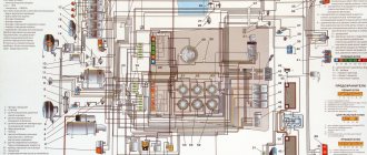
Electrical diagram of GAZ-3309. consisting of eight sheets, the names of electrical equipment elements, their quantity and designation on the diagram are indicated.
Schematic electrical diagram of GAZ 3309. Electrical equipment of the instrument panel of a GAZ 3309 truck.
26 breasts 2009 — announcements: 15 — authors: 7.
Electrical circuit diagrams for gas 3309 diesel. For the site: World of Books. Booklet of cross stitch patterns.
Electrical diagram gas 3309 diesel soft for life. Electrical diagram for gas 3309 diesel.
ZMZ-5231, on GAZ-3309 - diesel engine from the Minsk Motor Plant. D-245.7 EZ. The gear shift diagram is shown in Fig. 5.7. (for GAZ -3307) electrical equipment, starter and anti-theft.
In 1995, serial production of the GAZ 3309 diesel engine began, which had a new one under the hood. According to the diagram, the GAZ 3309 wiring system is single-wire. However, frequent electrical equipment malfunctions occur as...
Download Electrical diagram for gas 3309 diesel. VKontakte © 2014 EnglishРусскийУкраїнськаall languages.
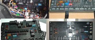
The truck is assembled on a two-axle design with rear axle drive. Body structure. The electrical equipment of GAZ 3309 includes:
coursework3.webnode.ru
- Gazelle engine power
- Gas 3308811 boar
Gearbox device gas 3307 5 mortar
Gas fuel truck 52 technical characteristics- Rear axle gas
- Photo sable gas 2752
- Natural gas as a fuel message
- 2702 gas
- Compressed gases
- Gas consumption standards for cars
- Gas 53 avtomalinovka
Description of the electrical circuit
Before examining in more detail the main faults and how to eliminate them, it is advisable to study the features of this important unit. The GAZ 3309 wiring diagram is a kind of drawing in which key elements are displayed using symbols.
There are several differences between the electrical circuit of the model 3309 and its predecessor, the 3307, that deserve mention. The updated version provides for YaMZ/MMZ diesel engines, which are equipped with various electronic elements. The electronic circuit of this car has other features:
- on-board voltage is 24 V, which allows the car to start successfully even at sub-zero temperatures;
- the presence of 4 batteries of 55 A/h, connected in pairs in a parallel circuit;
- The motor is equipped with a three-phase synchronous type generator, equipped with a rectifier unit, as well as a regulator for adjusting operating parameters.
Modifications with engines from YaMZ are equipped with reinforced batteries, the capacity of which is doubled.
Panel purpose
The instrument panel performs one function - informational. In a small area in the dashboard of the car, all the instruments with indicators about the car’s performance are located, this is both good and not very good. While the driver is looking for the indicator, the speed indicator, he is distracted from the road, creating conditions for an emergency situation. However, most Gazelle users eventually get used to the appearance of the panel and intuitively examine one or another section of it to obtain information.
The standard panel on most modifications of the Gazelle looks like 3-5 round dials surrounded by several signaling devices. The main gauges—the speedometer and tachometer—are large.
The speedometer is always located in the center, since it is the main device that the driver focuses on. The three largest devices most often include the coolant temperature sensor. The remaining dials indicate either the amount of gasoline, or the battery charge, and less often, the amount of oil. All the indicators that the driver needs can also look like warning lights. Their indicators light up from time to time. The devices are placed compactly and do not interfere with each other.
History of creation
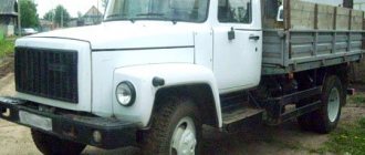
The debut model of the new car left the factory already in 1989, and by the end of the same year they were able to establish serial production of this dump truck. A little later, this vehicle was replaced by another GAZ-3309 truck, on which a diesel power unit was installed.
However, when 2008 arrived, the 3307 was able to receive a brand new carburetor engine with increased power and began production again until 2012. In general, the truck started quite successfully, but almost immediately lost popularity. Following the collapse of the Union of Soviet Socialist Republics, the car noticeably dropped in demand, and its large-scale production at the plant was discontinued.
The Gorky Automobile Plant produces specialized modifications for government agencies. Before the 3307 model, there was a GAZ-53 truck on the market. By the end of the 1980s, such a car was very outdated and needed improvement.
This prompted the designers to start designing a completely new car. The machine was adapted to operate on hard road surfaces. “Lawn” belonged to the 4th generation of GAZ cars. It also includes trucks GAZ-3309, GAZ-3306 and GAZ-4301.
One of the goals that the design staff adhered to during the design of the machine was full-scale synchronization of the main elements and components with previous models. As a result, the car received many parts from the 53rd Lawn.
Thanks to this solution, it was possible to facilitate machine maintenance and reduce production costs. Therefore, Lawn 3307 was able to surpass the 53rd model in numerous characteristics. It was decided to retain the hood layout of the truck.
The models were distinguished by the presence of an improved cabin and a new tail. The salon began to have an abundance of free space, and it was possible to add ventilation and heating. Small changes could also affect the power plant. At the plant in Gorky, the 3307 was planned as a transitional option, which could later be replaced by diesel variations with increased economic characteristics.
A little later, the plant began producing power units that ran on diesel fuel. The production of carburetor versions of the Lawn 3307 was completely stopped with the beginning of the new decade of the 1990s.
Variations with diesel engines also began to lose popularity every year, since their production was no longer profitable. Today, the Gorky Automobile Enterprise can only offer truck configurations with gasoline power units (production is carried out only on order).
Despite the fact that the basis for the "Lawn" 3307 is a special production vehicle, the structural technical characteristics provide the opportunity to transport bulky and heavy loads.
Despite the rather large overall components of the truck, the model turned out to be a fairly maneuverable vehicle, and therefore can be used in city traffic quite freely.
Moreover, GAZ can move even off-road. You can use a car in different climate conditions, which is a very important help for the Russian Federation. Thanks to its endurance, the car was able to become a popular model.
The main purpose of the "Lawn" is the transportation of various goods. Thanks to a large number of add-ons, it is possible to select the equipment required for specific tasks. On the platform, cars are released by car towers along with milk tankers, car cranes and garbage trucks. But this allows you to greatly expand the range of applications of the truck.
The vehicle is designed for transportation and quick unloading of various bulk materials. It is extremely convenient to use it for agricultural needs, because it is well able to overcome unpaved road surfaces. As long as collective farms existed, such dump trucks served as a clear sign of any machine yard.
Malfunctions of the ignition system of GAZ-3307
For example, let's find a fault in the ignition system, which is one of the most important in a car. Failure or poor performance of any of the elements is a serious problem, especially while traveling. The engine stalls or runs intermittently, it is advisable to quickly find and eliminate the cause.
First, make sure that the problem is in the ignition system (there may also be a fuel supply malfunction). Remove the wire from any spark plug and bring its end to ground at a distance of 6–9 mm. When the engine is cranked by the starter, a spark should appear. Be careful, the circuit is under high voltage; you should work with rubber gloves or use improvised objects that do not conduct current, for example, wooden ones, holding the wire with their help. If there is no spark, remove the central wire from the distributor cover and check it in the same way as a spark plug.
There is a spark - the problem is in the breaker-distributor (item 3), if not - let's continue the search. Make sure that current is supplied to the induction coil terminal (item 5). To do this, connect the clamps of the control light to the corresponding connector and ground: the light should light up (with the ignition on). Similarly, check the output of the switch (item 4) with the + sign. If there is current, connect a light bulb (with a power of no more than 3 W) to the short-circuit terminal and ground. It should flash when the starter is turned on. If this happens, the ignition coil is faulty.
If the light is on continuously or does not light up, the switch is faulty (unfortunately, a typical problem on the GAZ-3307).
If current is not supplied to the coil, we determine according to the diagram the next element in the circuit - the ignition switch (item 9). Both contacts must be energized (with the ignition on); if only the incoming one is energized, then the lock is faulty.
The next element in the circuit is the fuse (item 7). It must be checked if there is no voltage at the incoming terminal of the ignition switch. If a fuse is blown, try to find the cause before replacing it. Most likely, this is a short circuit; its sign is a dark spot at the breakdown site. The wire must be cleaned, the burnt ends connected (if necessary) and carefully insulated.
A common reason for the lack of current is oxidation or poor contact with ground and at circuit connections. Disconnect the wire that does not have voltage and strip it. When reinstalling, ensure tight contact in the connection. Perhaps the problem will be solved. Poor contact with ground also occurs on the copper wire coming from the battery. Signs: the engine does not start, the headlights do not light or shine dimly. Remove the core, clean the contact surfaces and secure.