- home
- Media center
- Articles
- ZIL instrument diagram
Menu
- News
- Articles
- Video materials
- Photo materials
- Publication in the media
- 3D tour
01.07.2021
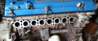
Since the most widely used trucks are the ZIL-130 and ZIL-131 models, it is their instrument layouts that will be discussed in this material. A modern car is a complex system of components and mechanisms that must interact smoothly. Therefore, an accurate color scheme is required.
Features of electrical equipment
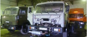
From 1966 to 1986, the ZIL-131 was produced unchanged. Then three modifications of it came out:
- with carburetor engine;
- with diesel engine;
- with unshielded wiring for civil needs.
The truck has high performance qualities, but besides these, its design has features that domestic manufacturers have not used on other vehicles:
- a gasoline engine with 8 V-shaped cylinders and 16 valves is installed;
- the traditional ignition system has been replaced with a contactless one equipped with an electronic switch;
- the use of shielded sealed electrical wiring made it possible to operate the ZIL 131 in any weather conditions.
Device, spare parts and components.
SPARE PARTS FOR TRACTORS ADJUSTING MTZ TRACTORS ___________________
DIESEL ENGINE PARTS ___________________
MTZ SPARE PARTS CATALOG ___________________
TECHNICAL CHARACTERISTICS OF TRACTORS ___________________
SPECIAL EQUIPMENT BASED ON MTZ AND ATTACHMENTS ___________________
AGRICULTURAL MACHINERY AND EQUIPMENT ___________________
Engine lubrication system D-245
The D-245 engine lubrication system is combined (Fig. 1): some parts are lubricated under pressure, others by splashing. The crankshaft and camshaft bearings, the idler gear bushing, the connecting rod bearing of the compressor crankshaft, the valve drive mechanism (rocker arms) and the engine turbocharger shaft bearing are lubricated under pressure from the oil pump.
Sleeves, pistons, piston pins, rods, pushers, camshaft cams and fuel pump drive MTZ-892, MTZ-92P are lubricated by splashing. On diesel engines with a full-flow centrifugal oil filter installed, a diagram of the lubrication system in accordance with Figure 1a.
Fig. 1a - Lubrication system D-245
1 — oil sump; 2 – piston cooling nozzles; 3 - crankshaft; 4 - camshaft; 5 — intermediate gear; 6 — oil filler neck; 7 — oil sump plug; 8 — oil receiver; 9 — oil pump; 10 – oil radiator; 11 – pressure reducing valve; 12 – oil filter; 13 – bypass valve; 14 – safety valve; 15 – pressure sensor; 16 – turbocharger; 17 – compressor; 18 – high pressure fuel pump; 19 – oil channel of the rocker arm axis,
Oil pump D-245 MTZ-892, MTZ-92P - gear type, single-section, bolted to the cover of the first main bearing. The oil pump supplies oil through the pipe and channels of the cylinder block to the centrifugal filter 12, in which it is cleaned of foreign impurities, wear products and oil decomposition products due to heating and oxidation.
From the centrifugal filter, the purified oil enters the radiator for cooling and through the oil supply tube to the turbocharger shaft bearing 16. From the oil cooler, the oil enters the diesel line.
In the housing of the centrifugal oil filter D-245 there are pressure-reducing valves 11, drain valves 13, and safety valves 14. When starting the engine, unheated oil, due to the high resistance of the radiator, flows directly into the engine line through the pressure reducing (radiator) valve, bypassing the radiator.
The safety valve (centrifugal filter valve D-245) is used to maintain oil pressure in front of the filter rotor at 0.8 MPa. When the pressure rises above the specified value, part of the crude oil is drained through the valve into the diesel crankcase. The pressure reducing and safety valves are not adjustable.
With the MTZ-892, MTZ-92P engine running, it is strictly forbidden to unscrew the pressure reducing and safety valve plugs. The drain valve is adjusted to a pressure of 0.25. 0.35 MPa and serves to maintain the required oil pressure in the main diesel line. Excess oil is drained through the valve into the crankcase.
From the main line of the engine, oil flows through channels in the cylinder block to all crankshaft main bearings and camshaft journals. From the main bearings, oil flows through channels in the crankshaft D-245 to all connecting rod bearings. From the first main bearing, oil flows through special channels to the bushings of the intermediate gear and the fuel pump drive gear, as well as to the fuel pump.
The parts of the valve mechanism D-245 MTZ-892, MTZ-92P are lubricated with oil supplied from the rear camshaft bearing through the channels in the block, the cylinder head, drilling in the IV rocker post into the internal cavity of the rocker axis and through the hole to the rocker bushing, from which the channel goes to the adjusting screw and rod. The pneumatic compressor receives oil from the main line through drillings in the cylinder block and a special oil pipeline. The oil is drained from the compressor into the diesel crankcase.
On diesel engines with an installed full-flow oil filter with a non-separable filter element and an oil cooler as part of the vehicle, the lubrication system diagram is in accordance with Figure 1b.
Fig. 1b - Lubrication system D-245 with a non-separable filter element and a liquid-oil heat exchanger
1 – oil sump; 2 – piston cooling nozzles; 3 – crankshaft, 4 – camshaft; 5 – intermediate gear; 6 – oil filler neck; 7 – oil sump plug; 8 – oil receiver; 9 – oil pump; 10 – liquid-oil heat exchanger (LHE); 11 – bypass valve; 12 – oil filter; 13 – bypass valve; 14 – safety valve; 15 – pressure sensor; 16 – turbocharger; 17 – compressor; 18 — high pressure fuel pump; 19 – oil channel of the rocker arm axis.
The D-245 oil pump, through the oil receiver 8, takes oil from the oil sump 1 and delivers it through the channels in the cylinder block and the channels of the oil filter housing to a full-flow oil filter, in which it is cleaned of foreign impurities, wear products and oil decomposition products due to heating and oxidation . From the oil filter D-245, the purified oil enters the radiator for cooling. From the oil cooler, oil flows into the oil line.
When starting the engine on cold oil, when the resistance to the passage of oil through the oil filter exceeds 0.13...0.17 MPa, the bypass valve 13 of the oil filter opens, the bypass (radiator) valve 11 of the oil cooler also opens, and the oil, bypassing the oil filter and oil radiator enters the oil line.
An adjustable safety valve 14 is built into the D-245 filter housing. It is designed to maintain oil pressure in the main oil line at 0.25. 0.35 MPa. Excess oil is drained through the valve into the diesel crankcase.
On diesel engines with an installed full-flow oil filter with a non-separable filter element and a liquid-oil heat exchanger - The D-245 oil pump, through the oil receiver 8, takes oil from the oil sump 1 and supplies it through the channels in the cylinder block and the channels of the oil filter housing to the liquid-oil heat exchanger, and then into a full-flow oil filter, in which it is cleaned of foreign impurities, wear products and oil decomposition products due to heating and oxidation. From the oil filter D-245, the purified oil enters the diesel oil line.
Possible wiring problems
The downside to the truck's proximity system in the old days was the lack of electronic parts and their reliability to handle harsh weather conditions.
Wiring problems may occur due to:
- circuit break;
- damage to current-carrying elements: cores, contacts, wires;
- poor contact at connection points;
- oxidation of terminals and contacts;
- insulation damage;
- lack of food.
An open circuit can be determined using a voltmeter or test light.
Broken wires must be replaced with intact ones. If it is not possible to make a replacement, you can temporarily connect the broken ends of the wire by wrapping them with insulating tape.
You should ensure that the contacts are clean, otherwise the current will not be able to break through the film formed from oil or oxide.
What you can do yourself
The problem of low oil pressure greatly complicates the relationship between lubricant consumption and level drop and the overall pressure in the system. In this case, a number of malfunctions can be eliminated independently.
- If leaks are detected, the problem is quite easy to localize and solve. For example, oil leakage from under the oil filter can be eliminated by tightening or replacing it. The problem with the oil pressure sensor, through which lubricant flows, is solved in a similar way. The sensor is tightened or simply replaced with a new one.
As for seal leaks, in this case you will need time, tools and skills. In this case, you can replace the front or rear crankshaft oil seal with your own hands in your garage with an inspection hole.
Oil leaks from under the valve cover or in the pan area can be eliminated by tightening fasteners, replacing rubber gaskets, and using special engine sealants. Violation of the geometry of the connecting planes or damage to the valve cover/pan will indicate the need to replace such parts.
- If the coolant gets into the engine oil, then you can remove the cylinder head yourself and replace the head gasket, while following all the recommendations regarding the removal and subsequent re-covering of the cylinder head. An additional check of the mating planes will indicate whether the cylinder head needs to be ground. If cracks are found in the cylinder block or head, repairs are also possible.
- In the case where the problem in the lubrication system is not so obvious, and you have to repair the car yourself, then at the very beginning you should measure the oil pressure in the engine.
To solve the problem, as well as taking into account an accurate understanding of where the oil pressure in the engine is measured and how it is done, additional equipment must be prepared in advance. Note that there is a ready-made device for measuring engine oil pressure available for free sale.
As an option, a universal oil pressure gauge will “Measure”. This device is quite affordable and comes with everything you need. You can also make a similar device with your own hands. To do this, you will need a suitable oil-resistant hose, pressure gauge and adapters.
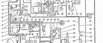
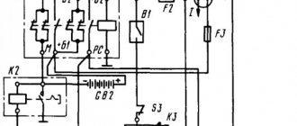
Electrical diagram of the ZIL-130 car
The electrical equipment system of the ZIL-130 car is single-wire. The negative terminals of the current sources are connected to the vehicle ground. Rated voltage 12 V. The car uses low voltage wires of the PGVA type and high voltage wires of the PVV type.
Checking the wires for proper insulation is carried out by external inspection. If a bare spot is found on low voltage wires, it must be insulated (wrapped) with insulating tape. High voltage wires with broken insulation are replaced with new ones and cannot be repaired.
To determine whether a wire is broken, you need to use a probe with a control light. To identify the location of the break, a wire with a spring tip is connected to ground, and the tip of the tip begins to touch the circuit clamps in the direction from the non-working device to the battery. If there is a large distance between the terminals or if there are no terminals, you can pierce the wire insulation with the tip of the tip.
The check is carried out until the light comes on. The location of the wire break will be between the point of contact where the light bulb came on and the closest point to it where the light bulb is not yet on. The broken wire must be replaced. As a temporary measure, you can connect the ends of the broken wire and wrap the connection with insulating tape.
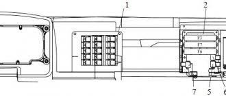
If the wire is shorted to ground, check the wire insulation. Since the circuit of many current consumers is protected by fuses, usually the circuit in which a short circuit occurs is immediately opened by the corresponding fuses.
To eliminate the short circuit, carefully inspect all wires and wrap any detected areas with damaged insulation with insulating tape.
To maintain the electrical wiring in good condition and prevent chafing of the wires, it is necessary to clean the wires from dirt and dust and check the wire fastening brackets.
The warning lamp for emergency reduction of oil pressure lights up when the pressure in the lubrication system drops to 60–30 kPa (0.6–0.3 kgf/cm3), when the ignition is turned on, and goes out when the engine is running. A short flashing of the lamp when the engine speed decreases does not indicate a malfunction of the lubrication system, if the lamp immediately goes out when the engine speed increases.
The turn signal warning light comes on when the turn signals are turned on.
The speedometer shows the speed of the car in kilometers per hour, and the total counter installed on it shows the total mileage of the car in kilometers.
Indicators for oil pressure, coolant temperature, fuel level and ammeter are combined into a combined instrument KP205.
An ammeter with a scale of 30—0—30 A is used to determine the strength of the charging (arrow deviates toward the “+” sign) or discharge (arrow deviates toward the “—”) current of the battery.
The coolant temperature gauge shows the temperature of the fluid in the cylinder head. The temperature indicator scale is graduated at 120 °C.
The oil pressure gauge shows the pressure in the engine lubrication system.
The fuel level indicator shows the amount of fuel in the tank; has a scale with divisions 0, 1/2 and P, corresponding to an empty tank, half the volume and full tank volume. The indicator is valid when the ignition is on.
For the ZIL-130V1 truck tractor, which has two fuel tanks, the fuel level indicator is equipped with two sensors (according to the number of tanks) and shows the amount of fuel in each tank separately. There is a switch on the instrument panel to turn on the right or left tank sensor. When the switch handle is moved to the right, the right tank sensor is turned on, and when moved to the left, the left tank sensor is turned on.
Rice. 1. Controls and instrumentation: 1 — speedometer; 2 — control lamp for high beam headlights; 3 - ammeter; 4 — coolant temperature indicator; 5 — warning lamp for emergency reduction of oil pressure; 6 — pressure gauge (two-pointer) for monitoring air pressure in the pneumatic brake drive system; 7 — windshield wiper blades; 8 — control handle for the damper of the cabin heater duct; 9 — switch for the electric motor of the cabin heater;
The pressure gauge (two-pointer) for monitoring air pressure in the pneumatic brake drive system has two scales: the upper scale shows the pressure in the air cylinders, the lower scale shows the pressure in the brake chambers.
The following controls are located below the instrument panel.
The combined ignition and starter switch is turned on by turning the key clockwise to two positions. At the first fixed position, the ignition is turned on, and when the key is further turned all the way, the starter is turned on. Turn the ignition off by turning the key in the opposite direction. The starter, if there is an alternating current generator, does not automatically turn off when the crankshaft speed increases, so it is necessary to turn off the starter immediately as soon as the engine starts running.
The carburetor throttle valve control handle is locked in intermediate positions; when pulled out, the valves open. To close the dampers, release the handle by turning it around its axis and press it all the way.
The carburetor choke control knob allows you to partially or completely close the air damper and thereby enrich the working mixture. After the engine warms up and the car starts moving, the handle should be recessed.
Rice. 2. Controls: 1 — radiator shutter control handle; 3 — gear shift lever; 4 — direction indicator switch; 5 — windshield washer spray; 6 — instrument panel; 7 — windshield washer pedal; 8 — clutch pedal; 9 — foot switch for headlights; 10** brake pedal; 11 — throttle valve control pedal (fuel pedal); 12 *" button Pneumatic horn of tractor unit
The handle of the central headlight switch can be set in three fixed positions: O - the handle is fully pressed - the lighting is off; I - the handle is extended halfway - the rear and front lights are on; II - the handle is fully extended - the rear lights and headlights are on;
Control knob for the cabin heater channel damper: when the handle is recessed, the damper closes, the intensity of the windshield blowing increases and the supply of warm air to the driver’s feet is turned off.
When the handle is pulled out, the damper opens, the supply of warm air for blowing the windshield decreases, and the supply of warm air to the driver’s feet begins. The amount of warm air supplied to the windshield and to the driver’s feet can be adjusted by setting the knob to intermediate positions.
The cabin dome light switch turns on the dome light lamp regardless of the position of the central light switch knob.
The cabin heater electric motor switch has three positions (off, increased angular speed of the electric motor, reduced angular speed); Moving the switch knob to the left turns on the increased angular velocity, and moving the knob to the right turns on the reduced angular velocity. When the handle is in the middle position, the electric motor is turned off.
The windshield wiper control valve handle is used to regulate the speed of the windshield wiper. By rotating the knob, you can adjust the speed of the windshield wiper. When you rotate the knob counterclockwise, the intensity of the wiper increases, and when you rotate it in the opposite direction, it decreases.
Gear shift lever. The diagram of the lever positions when engaging various gears is shown in Fig. 3.
The parking brake lever operates a central drum-type brake mounted on the transmission driven shaft.
The windshield washer pedal is located on the floor on the left side of the cab. Each time you press it, jets of water from the spray nozzles wash the windshield, and you must turn on the windshield wiper.
Rice. 3. Gear shift lever position diagram
The headlight foot switch is used to switch the high beam to low beam and vice versa from low to high beam when the central switch handle is fully extended.
The turn signal switch is mounted on the steering column. Moving the switch knob down turns on the left turn indicators, and when moving the knob up, turns on the right turn indicators. When the turn indicators are turned on, the warning lamp on the instrument panel lights up intermittently green. After the turn is completed, the switch turns off automatically.
The radiator shutter control handle is attached to a bracket to the left wall of the cab. To close the blinds, you need to pull the handle towards you, and to open it, push it all the way. To partially close the blinds, the handle is placed in one of the intermediate positions.
The pneumatic horn button is installed on the ZIL truck tractor.
Maintenance of the D-245E3 lubrication system
To ensure normal operation of the diesel engine, observe the following requirements for servicing the lubrication system:
— fill the oil sump only with oil recommended by the manufacturer.
— change the oil and oil filter in a timely manner, guided by the deadlines or according to the information from the electronic diesel control system with the corresponding blink code;
- constantly monitor the oil pressure value using the pressure indicator located on the instrument panel (when the diesel engine is operating at a rated speed and coolant temperature of 85. 95 ° C, the oil pressure should be at the level of 0.25. 0.35 MPa, the value is allowed pressure on a cold engine up to 0.8 MPa);
Figure 1 – Adjusting oil pressure.
— adjust the pressure value in accordance with Figure 1 as follows:
— unscrew plug 4, remove gasket 5;
— in the channel of the oil filter housing 3, use a screwdriver 7 to turn the adjusting rod 6 one turn in the direction of increasing or decreasing the pressure value (depending on the actual pressure);
— install gasket 5 and tighten plug 4;
— if necessary, repeat these adjustment steps.
It is PROHIBITED to make adjustments while the diesel engine is running.
Checking the oil level in the diesel crankcase
Carry out the check before starting the diesel engine using an oil gauge located on the diesel cylinder block.
The oil level should be between the lower and upper marks of the oil gauge in accordance with Figure 2.
The check must be done no earlier than 3-5 minutes after stopping the diesel engine, when the oil has completely drained into the crankcase.
It is prohibited to operate a diesel engine with the oil level in the crankcase below the lower and above the upper marks on the dipstick.
Figure 2 - Checking the oil level in the diesel crankcase.
Changing the oil in the diesel crankcase
Change the oil in the crankcase of diesel engines every 10 thousand kilometers, and in cases of using backup oils or fuel with a high sulfur content - every 5 thousand kilometers.
Drain used oil only from a warm diesel engine.
To drain the oil, unscrew the oil sump plug. After all the oil has flowed out of the crankcase, screw the plug back into place.
Fill diesel oil through the oil filler pipe to the level of the top mark on the dipstick.
Fill the oil sump only with oil recommended in this manual and appropriate for the period of operation.
Replacing the oil filter
Figure 3 – Options for installing an oil filter without LMC and with LMC on D-245E3 diesel engines
Replace the oil filter every 10 thousand km or according to the results of diagnostics of the “COMMON RAIL” system in accordance with Figure 3 simultaneously with changing the oil in the diesel crankcase in the following sequence:
— unscrew the FM 009-1012005 or M5101 filter from fitting 3, using a special key or other available means;
— screw a new filter FM 009-1012005 or M5101 onto the fitting.
When installing the filter on the fitting, lubricate gasket 4 with engine oil.
After the gasket touches the supporting surface of filter housing 1, tighten the filter another 1.1.5 turns.
Install the filter on the housing only by hand.