Technical characteristics of the front axle
Beam – Stamped I-section
Steering knuckles - Forged, fork type
Front wheel alignment angles:
Longitudinal angle of inclination of the kingpin without load – 1-15
Camber angle-1
Cross pin tilt – 8
Maximum wheel rotation angle – 45
Wheel toe - 2-5
Front axle ZIL-130
Front axle ZIL and its structure
Technical characteristics of the front axle
Beam – Stamped I-section
Steering knuckles - Forged, fork type
Front wheel alignment angles:
Longitudinal angle of inclination of the kingpin without load – 1-15
Camber angle-1
Cross pin tilt – 8
Maximum wheel rotation angle – 45
Wheel toe - 2-5
Front axle ZIL-130
GAZ-3307, 3309 » Rear axle » Replacement of the steering knuckle king pin and king pin bushings
5. Unscrew the bolts and remove the pin covers.
6. Unscrew the nuts, remove the washers and knock out the kingpin locking pins.
7. Using a special drift (Fig. 1) with replaceable heads, knock down the kingpin from the steering knuckle (Fig. 2).
8. Remove the steering knuckle, king pin thrust bearing and king pin rubber O-rings.
9. Clamp the steering knuckle in a vice (Fig. 3) and use a mandrel to knock out both pin bushings.
10. Clean the holes for the king pin in the steering knuckle and the lubrication holes.
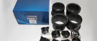
11. Using a mandrel, install new bushings so that the holes in the bushings coincide with the holes in the knuckle bosses, and the open ends of the lubrication grooves of the bushings face toward the front axle beam (Fig. 4).
12. Unroll both new bushings simultaneously using a special reamer (Fig. 5) to a diameter of 30 mm -
13. Clean the bushings of metal shavings after deployment and apply a thin layer of lubricant to each bushing.
14. Having previously lubricated the rubber sealing rings and the annular grooves in the knuckle bosses, install the rings.
REMOVAL AND DISASSEMBLY OF THE FRONT AXLE
Before starting work, the car should be cleaned of dirt and washed.
To remove the front axle from the car, you need to lift the car and install stands under the front axle beam, unscrew the wheel nuts and remove them.
Loosen the clamps of the flexible hoses supplying air to the brake chambers and disconnect these hoses.
Unscrew the nut securing the lower end of the shock absorber and remove the bushing and washer, disconnect the lower end of the shock absorber. Disconnect the end of the tie rod from the bipod.
Unscrew the nuts securing the front spring stepladders, remove the shock absorber brackets and stepladders.
Raise the car, remove the six lower leaf springs and the lining from the front axle beam, and remove the front axle from the stands.
front axle hub ZIL
To install the front axle, all operations must be done in reverse order.
The front axle can be removed from the vehicle by disconnecting the spring mountings from the frame.
Dismantling the front axle. The method of mooring the bridge is shown in Fig. 6-19. Install and securely fasten the front axle assembly with the transverse steering rod and brake chambers on the disassembly and assembly stand (Fig. 6—20).
Remove the tie rod by unscrewing and unscrewing the castle nuts of the tie rod ball pins, press the pins out of the steering arms and remove the tie rod (Fig. 6-21).
Stand for dismantling the ZIL bridge
TRUCKS GAZ, ZIL, KAMAZ, URAL, MAZ, KRAZ
GAZ cars
- GAZ-53
- GAZ-66
- GAZ-3307
- GAZ-3308, 33081
- GAZ-3309
- GAZ-3310 Valdai
- GAZ-2705 Gazelle
ZIL cars
KAMAZ vehicles
- KAMAZ-4310, 43118, 43114
- KAMAZ-5320, 55111, 53212
- KAMAZ-65115, 6520, 65117
- KAMAZ-4308
- Engine KAMAZ-740
MAZ cars
- MAZ-5516
- MAZ-5551
- Engine YaMZ-238
KRAZ cars
Front axle ZIL-130
Close the brake pads by turning the clutch (along the axis of the worm) of the adjusting brake lever counterclockwise.
Unscrew and remove the pin connecting the brake chamber rod fork to the adjusting brake lever.
Unsplit the splined end of the expansion knuckle shaft and remove the washer, adjusting brake lever and adjusting washer from the shaft. To make it easier to remove the lever, you need to remove it from the brake chamber rod fork by turning the lever axis.
Unscrew the bolts securing the hub cover, remove the cover and cover gasket; remove grease from the bearing lock nut and wipe the lock nut.
Bend back the lock washer 7 and unscrew the lock nut 5 of the hub bearings, remove the lock washer 7 and the lock ring 8.
Unscrew the hub bearing nut.
Ball pin remover
Remove using a mod remover. And 804. 27. 000 hub assembly with brake drum from the steering knuckle (Fig. 6-22) and remove cuff 3 from the hub. When removing the hub, the outer bearing is also removed.
Wipe the surface of the axle and the inner bearing with a rag soaked in diesel fuel or kerosene.
Remove the outer tension springs, press out the pads with a mounting spatula and remove the rollers. Remove the pin from each brake pad axle, remove the pad axle lining, and then remove the brake pads with release springs from the axles.
Wipe the brake pad axles with a rag soaked in diesel fuel and check the condition of the axles. There should be no significant wear on the surface of the axles (in the form of
ring grooves) and wear. If there is a hole and the axle diameter is less than 27.74 mm, it is necessary to replace the axles by unscrewing the axle mounting nuts and pressing out the axles.
Remove the expansion knuckle shaft seals from the annular grooves of the bracket. The cuff support ring should be compressed only if there are grooves or holes on the surface of the ring
Unscrew the nuts and bolts securing the brake shield and remove the shield assembled with the pad axles.
Removing the hub
Unscrew the bolts securing the upper and lower covers 27 (see Fig. 6-8) of the kingpin and remove the roofs and cover gaskets. Unscrew the nut securing the wedge 28 of the king pin and knock the wedge out of the hole in the front axle beam.
Press out using tool mod. R-176 or KS-2 or 2504 (Fig. 6-24) steering knuckle pin 23 (Fig. 6-25) and remove the steering knuckle 26, adjusting washer 29 and support bearing 20.
After removing the steering knuckle, remove the cuff with the cage from the upper eye, and support bearing 2 from the lower eye! (See Figure 6-18) and support washer.
Removing the inner bearing
Unscrew and unscrew the castle nut securing the upper arm 19 and press the arm out of the steering knuckle eye hole. This work is performed only for the left steering knuckle. Unscrew and unscrew the fastenings of the lower lever 17 and press the lever out of the hole in the steering knuckle eye.
Pressing out the kingpin
Carry out similar work for the right steering knuckle.
These works are carried out only if it is necessary to replace the levers in case of loose fitting of the lever and wear of the hole in the lever head for the ball pin. The technical requirements for replacing the steering knuckles are listed in the table below. 6-10. To make it easier to unscrew the castle nut securing the lever and press it out, it is recommended to fill the place where the lever is attached with brake fluid and let it sit for 3...5 minutes.
Wash the parts of the hubs, brake mechanisms, bearings, axles in the MS-b, MS-8 TU 6-15-978-76 solution, and blow them off with compressed air.
If it is necessary to replace the pin bushings, they must be pressed out using a press.
If necessary, press the outer bearing races out of the hub.
Press the pin bushings into the lugs of the steering axle. After pressing the bushings, stretch them to size 45+0.60 mm. When pressing bushings, the hole in the bushing must coincide with the hole (oil channel) in the steering knuckle eye.
Press in using mandrels mod. And 806.05.005, And 806.05.004 and And 806.05.006 outer rings of hub bearings and a cuff in the hub.
If necessary, press the bushings out of the expansion knuckle bracket, having first removed the sealing rings.
Press the bushings into the expansion knuckle bracket and rotate the bushings to the size of the expansion knuckle shaft. Install the O-rings into the bracket. The O-rings can be installed after the bracket is secured to the brake guard.
Carry out similar work for the right hub and steering knuckle.
Important points during assembly
After you have done what you wanted, you need to assemble everything correctly. If the steering knuckle bushings have been changed, they must be turned out. This is done with a special tool - a reamer, in order to adjust the desired diameter. When installing, the kingpin should fit snugly into the ears of the fist and not have any play. Naturally, everything needs to be generously lubricated. It is better to do this with nigrol, as it retains its properties for a long time. Regular oil will leak out, and thick solid oil will begin to coke, as a result of which the rod may sour again.
It is recommended to lubricate new pivots with nigrol during installation.
Don't forget to install the support bearing in the boot , as well as rubber seals that will trap all the dirt that gets under the king pin. If after assembly the steering knuckle moves in the axial direction, you can use washers of this thickness to eliminate this play. You can adjust them directly under the bearing. An ideally working mechanism should turn tightly and at the same time have no axial or radial clearances. After checking, at the very end the pin is inserted and tightened.
Ball joint device
If you drive carefully, you won’t have to do such things so often.
Source
Assembly of the front axle of the ZIL-5301 car
1. Press the bushings using a special mandrel (see Fig. 1) into the holes of the steering knuckle flush with the surface so that the open ends of the grooves on the bushings face inside the knuckle (the pressing force must be at least 10 kN). The pressed bushings should not protrude above the installation ends of the sealing collars to avoid cutting them.
The lubrication holes in the bushings must line up with the oiler holes in the knuckles. Iron the bushings to a size of at least 29.55 mm, ensuring their alignment.
2. Install the front axle beam on the stand shown in Fig. 2.
3. Insert sealing rings into the sockets of the steering knuckle, into the lower socket - a thrust ball bearing, having previously lubricated it with Litol-24 grease, and into the upper socket - adjusting shims 8 (Fig. 3).
4. Install the steering knuckle 1 and connect it to the bridge beam by inserting a special mandrel from below into the holes of the knuckle and the beam (Fig. 4).
5. Check the gap “C” between the upper support of the steering knuckle and the upper plane of the beam support (see Fig. 3). The gap should be no more than 0.2 mm.
If necessary, adjust the gap using shims 8. The total number of shims should not be more than two.
6. Press the king pin on top, having previously lubricated it and the bushings with engine oil. Press the kingpin so that the flat on it coincides with the hole in the boss of the beam for the wedge.
How to remove the kingpin
There are several ways to remove the kingpin from the fist. You can squeeze it out with a press or simply knock it out, or you can use your imagination and come up with your own method. But for now it’s worth considering two main options.
Knocking out the kingpin
The first and most common way to remove a rod that has soured in a beam is to simply knock it out with a hammer or a heavy hammer. This must be done carefully, without fanaticism, so as not to damage the steering knuckle.
For such a procedure, you will need a heavier hammer, since the blow must be strong, as well as a guide. It should be 2-3 mm smaller in diameter than the kingpin itself. Before starting, it is advisable to place something under the beam to create good resistance. Then we direct the tip at the soured rod and strike it with powerful blows.
Knocking out the king pin using a hammer and a jig
The process may take a long time, since first it will need to be torn from its place. If you managed to do this, we can assume that the matter is in the bag. At this point, it is important to consider the hardness of the adapter, because if the metal is softer than the rod, it will flatten and get stuck in the steering knuckle. If, on the contrary, the attachment is harder, then the pin can be riveted, as a result of which it will increase in diameter and will not fit into the beam socket. Then you won't be able to get it out of there at all. According to mechanics, the best attachment is an old axle machined on a lathe. Its hardness and dimensions will be suitable and the rod can be easily removed without any problems.
You can watch the video for more details about knocking out pins:
Pressing out the kingpin
The second method is a little simpler, although it requires a special tool. It is often used when removing the king pin on trucks, but it can also be used for passenger cars. First, you need to make your own (or buy, but the cost of such a device will be from 70,000 rubles and more) a certain puller, which is a rectangular structure. Take a small thick plate and two studs, which must be welded to it at a certain distance (about 30 cm). Then a second plate is used, with holes made for them. The entire structure is placed coaxially under the kingpin, and the plate with holes is screwed on top with nuts. In this way, a closed frame is obtained, which will serve as a stop when squeezing out the soured rod.
Half the battle done! Now all that remains is to install a hydraulic jack (preferably with a lifting capacity of at least 50 tons), select an adapter for the kingpin and begin the process itself. It turns out that from above the steering knuckle rests against the upper plate, screwed with nuts to the studs, and from below the jack presses. It, in turn, collides with the main, lower plate, which creates a lot of force. At a certain pressure, the rod itself will begin to climb out of the beam.
Pressing out the kingpin using a special puller and a hydraulic jack
You can do without a jack, but it takes longer and is a little more difficult to implement. You will have to make or order a puller, which is shown in the figure below. It is attached to the wheel hub so that the bolt from above fits into the hole in the kingpin. The bolt is then manually screwed into this hole, thereby pressing out the king pin.
Pressing out the king pin using a puller
You can watch the video for more details about the process of pressing out the pins:
These are the two main ways in which you can remove even a tightly stuck king pin. They were invented by car owners who once faced this problem. Of course, this is not entirely technologically advanced, but it is effective and masculine. Moreover, if you oiled your fist in a timely manner, then knocking out the rod will not be difficult, and brute force may not be needed. True, this rarely happens.
Restoration, replacement of parts
During repairs, the front axle beam must be checked for bending and torsion using a device that is installed on the spring platform.
The prism of the device is directed along a clamp installed in the hole for the kingpin and secured with an expanding collet; determination of bending and twisting, as well as the inclination angle of the hole for the kingpin, is carried out using scales.
The beams are straightened in a cold state under a hydraulic press. After editing, the angle of inclination of the axis in the holes for the kingpin to the vertical axis should be within 7 45 ... 8 15.
The spring removed from the car is installed on the table of the stand for disassembling and assembling springs and secured to the side surfaces of the sheets, then the nuts of the spring clamp bolts are unscrewed, the bolts are knocked out and the spacers are removed. Loosen the spring fastening, lay it with its side surface on the stand table and secure it to the top and bottom sheets. Then unscrew the nut of the center bolt, loosen the clamp of the stand and remove the spring disassembled into sheets. Check the condition of the spring leaves, clamps and cups.
There should be no cracks or debris on the spring leaves. Wear of spring sheets with a thickness of more than 1.0 mm is not allowed. There should also be no breaks or cracks on the spring clamps. Loosening the rivets securing the clamps and cups is not allowed. Wear of the hole in the bushing of the rear spring ear to a size greater than 40.4 mm is not allowed.
Spring sheets suitable for assembly are cleaned of corrosion, straightened on a mod.2470A GARO machine according to a template and lubricated with graphite lubricant.
The spring sheets prepared for assembly are put on the mandrel in order, placed with the side surface of the sheets on the stand and compressed. Remove the mandrel, install the center bolt and tighten the bolt nut. The spring sheets of the ZIL-130 car are assembled so that the stamped protrusions fit into the depressions of each sheet. Pinch bolts and spacer bushings are installed in the eyes of the clamps and nuts are screwed onto the bolts. After assembly, check the spring deflection arrow by pulling a thin wire with a weight along the end surfaces of the cups of the upper main leaf of the front spring. If the deflection values are less than those indicated in Table 7, the sheets are straightened.
Table 8 — Spring deflection in a free state, mm
Car ZIL - 130
The front spring is installed in the reverse order. To correctly install the fastening of the ends of the spring in the rubber supports, it is straightened using a device to a horizontal position. If the springs are installed incorrectly, the rubber supports do not self-align, which leads to their rapid wear.
If the pin has one-sided wear of no more than 0.15 mm, it is lubricated with engine oil and installed in place in the same bushings, turning 90° until the flat for the locking pin matches the hole for the pin in the front axle beam. Simultaneously with the rotation of the kingpin, the axial clearance is established by placing an adjusting shim of the required thickness between the upper boss of the steering knuckle and the boss of the beam or by replacing the thrust bearing when reducing the depth of the lubrication grooves of the middle cermet washer of the thrust bearing to 0.5 mm. Before installation, the new bearing is lubricated with grease 1 - 13.
Useful tips and tricks
- There have been cases when a person forgot to knock out the locking pin or did not notice it and began to rivet the kingpin. This happens due to inattention, as well as ignorance of the node itself. If you carefully examine the beam in the area of the rod seat, you will notice a small iron pin. So this is the pin. It keeps the pin from rotation, as well as from axial displacement; therefore, before knocking out, you must first pull out this pin, and then carry out further manipulations.
Article: 130-3000101, additional articles: 03-29-43M, 120-3001019
Order code: 139485
- You may need
- show more
- Buses / LAZ / LAZ 695N4 drawing
- » href=»/catalog/laz-47/avtobusy-36/laz_695n-222/os_perednyaya-74/#part362028″>Front axle knuckle washerFront axle / Front axle
- » href=»/catalog/laz-47/avtobusy-36/laz_695n-222/os_perednyaya-74/#part362033″>Steering knuckle bushingFront axle / Front axle
- » href=»/catalog/laz-47/avtobusy-36/laz_695n-222/os_perednyaya-74/#part362034″>King pin Front axle / Front axle
- » href=»/catalog/laz-47/avtobusy-36/laz_695n-222/os_perednyaya-74/#part362029″>Front axle knuckle washer adjustableFront axle / Front axle
- Buses / PAZ / PAZ-32052 drawings
- » href=»/catalog/paz-20/avtobusy-36/paz_3205-131/os_perednyaya-84/#part395333″>Steering knuckle bushingFront axle / Front axle
- » href=»/catalog/paz-20/avtobusy-36/paz_3205-131/os_perednyaya-84/#part395340″>Knuckle adjusting washer Front axle / Front axle
- Buses / PAZ / PAZ-3205-1103 drawings
- » href=»/catalog/paz-20/avtobusy-36/paz_3205_110-414/os_perednyaya_i_povorotnye_kulaki-75/#part1286730″>Knuckle washer Front axle / Front axle and steering knuckles
- » href=»/catalog/paz-20/avtobusy-36/paz_3205_110-414/os_perednyaya_i_povorotnye_kulaki-75/#part1286706″>Steering knuckle bushing Front axle / Front axle and steering knuckles
- » href=»/catalog/paz-20/avtobusy-36/paz_3205_110-414/os_perednyaya_i_povorotnye_kulaki-75/#part1286729″>Steering knuckle adjusting washer Front axle / Front axle and steering knuckles
- Buses / LAZ / LAZ 695B4 drawings
- » href=»/catalog/laz-47/avtobusy-36/laz_695b-219/perednyaya_os-73/#part353745″>Steering knuckle bushingFront axle / Front axle
- » href=»/catalog/laz-47/avtobusy-36/laz_695b-219/perednyaya_os-73/#part353746″>King pinFront axle / Front axle
- » href=»/catalog/laz-47/avtobusy-36/laz_695b-219/perednyaya_os-73/#part353741″>Front axle knuckle washer adjustableFront axle / Front axle
- » href=»/catalog/laz-47/avtobusy-36/laz_695b-219/perednyaya_os-73/#part353740″>Front axle knuckle washerFront axle / Front axle
- Buses / LAZ / LAZ 699R3 drawing
- » href=»/catalog/laz-47/avtobusy-36/laz_699r-220/os_perednyaya-108/#part368648″>King pin Front axle / Front axle
- » href=»/catalog/laz-47/avtobusy-36/laz_699r-220/os_perednyaya-108/#part368646″>Front axle knuckle washer adjustableFront axle / Front axle
- » href=»/catalog/laz-47/avtobusy-36/laz_699r-220/os_perednyaya-108/#part368647″>Front axle knuckle washer Front axle / Front axle
- Buses / PAZ / PAZ-672M4 drawing
- » href=»/catalog/paz-20/avtobusy-36/paz_672m-393/os_perednyaya_i_rulevye_tyagi-95/#part1280727″>Knuckle washer Front axle / Front axle and tie rods
- » href=»/catalog/paz-20/avtobusy-36/paz_672m-393/os_perednyaya_i_rulevye_tyagi-95/#part1280693″>Steering knuckle bushingFront axle / Front axle and steering rods
- » href=»/catalog/paz-20/avtobusy-36/paz_672m-393/os_perednyaya_i_rulevye_tyagi-95/#part1280725″>Steering knuckle adjusting washerFront axle / Front axle and steering rods
- » href=»/catalog/paz-20/avtobusy-36/paz_672m-393/os_perednyaya_i_rulevye_tyagi-95/#part1280694″>Steering pin Front axle / Front axle and tie rods
- Buses / PAZ / PAZ-320533 drawings
- » href=»/catalog/paz-20/avtobusy-36/paz_32053-679/os_perednyaya__pr_vo_ao__kaaz__-92/#part1884865″>Knuckle washer Front axle / Front axle (manufactured by JSC KAAZ)
- » href=»/catalog/paz-20/avtobusy-36/paz_32053-679/os_perednyaya__pr_vo_ao__kaaz__-92/#part1884840″>Steering knuckle bushing Front axle / Front axle (manufactured by JSC KAAZ)
- » href=»/catalog/paz-20/avtobusy-36/paz_32053-679/os_perednyaya__pr_vo_ao__kaaz__-92/#part1884864″>Knuckle adjusting washer Front axle / Front axle (manufactured by JSC KAAZ)
- Buses / ZIL / ZIL-32502 drawings
- » href=»/catalog/zil-10/avtobusy-36/zil_3250-937/usilennaya_perednyaya_os_i_rulevye_tyagi__variant_2_-72/#part2419201″>Washer Suspension / Reinforced front axle and steering rods (option 2)
- » href=»/catalog/zil-10/avtobusy-36/zil_3250-937/usilennaya_perednyaya_os_i_rulevye_tyagi__variant_2_-72/#part2419204″>Adjusting knuckle washer Suspension / Reinforced front axle and steering rods (option 2)
- Trucks and trailers / ZIL / ZIL 431410 (130)6 drawings
- » href=»/catalog/zil-10/gruzoviki_i_pricepy-33/zil_431410__130_-39/perednyaya_os_i_rulevye_tyagi-47/#part497839″>Support bearing washerFront axle / Front axle and steering rods
- » href=»/catalog/zil-10/gruzoviki_i_pricepy-33/zil_431410__130_-39/perednyaya_os_i_rulevye_tyagi-47/#part497840″>Adjusting steering knuckle washer Front axle / Front axle and steering rods
- » href=»/catalog/zil-10/gruzoviki_i_pricepy-33/zil_431410__130_-39/perednyaya_os_i_rulevye_tyagi-47/#part497841″>King pin Front axle / Front axle and steering rods
- » href=»/catalog/zil-10/gruzoviki_i_pricepy-33/zil_431410__130_-39/perednyaya_os_i_rulevye_tyagi-47/#part200001589″>Bearing ringFront axle / Front axle and steering rods
- » href=»/catalog/zil-10/gruzoviki_i_pricepy-33/zil_431410__130_-39/perednyaya_os_i_rulevye_tyagi-47/#part200001583″>Washer Front axle / Front axle and steering rods
- » href=»/catalog/zil-10/gruzoviki_i_pricepy-33/zil_431410__130_-39/perednyaya_os_i_rulevye_tyagi-47/#part497818″>Steering knuckle bushingFront axle / Front axle and steering rods
- Trucks and trailers / ZIL / ZIL-53012 drawing