Setting the working width
The adjustment is made by rearranging the tractor wheels :
- on the T-150K the track width is set to 1680 mm instead of 1860 mm;
- on a MTZ type tractor, the right wheel is shifted from the axis by 800 mm, the left wheel by 700 mm.
For tractors of traction class 3, the longitudinal links of the hitch are shifted to the right up to 150 mm . The brackets on the cross beam of the plow frame are shifted to the left position up to 220 mm . For the PLP-6−35 plow, the additional loader rod is attached to the plow frame in the left position.
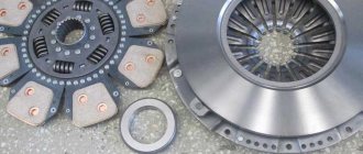
How to hang a plow
How to hang a plow
The design of the mounted device of the T-74, DT-75 and T-150K tractors allows it to be rebuilt according to a two- or three-point connection scheme with agricultural machines, in particular plows, as shown in the figure. There may be specific features depending on the type of machine and working conditions.
If, with a three-point hitch, the articulated four-link links are positioned in such a way that the point of intersection of the lines of these links (instantaneous center of rotation - ICV) approximately coincides with the center of the supporting surface of the tracks (see figure), then when turning, the additional forces of resistance to turning the tractor will be less than with two-point hitch, 2.5–3 times.
Plow hitch : 1 - three-point hitch; 2 — two-point hitch; 3 — lower links; 4 - top link; 5—instantaneous center of rotation (ICR).
At the beginning of a turn, when the friction clutch of the lagging tractor track slips, the implement practically maintains its position relative to the previous direction of movement, like a pendulum trailer. This provides less resistance to turning the plow. Once both tracks are engaged, they turn the plow in the other direction. Therefore, with a central three-point adjustment, the load in the transmission is reduced, and the tractor has greater freedom of rotation relative to the plow.
It should only be noted that the locking chains with a three-point hitch, as with a two-point hitch, must be loosened in the working position of the plow, and tightened in the transport position. The advantages of a three-point hitch over a two-point hitch are most clearly evident if the working width of the implement is equal to or greater than the overall width of the tractor. For the T-150 and T-74 tractors, a five-furrow plow meets this condition. To ensure the required distance from the wall of the furrow to the right caterpillar with aggregated four-furrow, and especially three-furrow plows, they have to be shifted to the right along the way. Therefore, hanging according to the three-point scheme becomes difficult or even impossible. This circumstance is the only and not very convincing argument in favor of the existing hitch on tracked tractors, which allows for the possibility of changeovers to a two- and three-point layout. When the plow is offset relative to the tractor, controllability is unsatisfactory in any setting, since the traction load is distributed unevenly across the tracks.
Usually, during theoretical analysis, supporters of a three-point hitch do not take into account the presence of the upper (central) link of the hitch, the spring of which is deformed less when turning a tractor with a two-point hitch. This is another reason for controversy. However, as experience shows, when properly aggregated, for example, a T-150 crawler tractor with a five-furrow mounted plow, a three-point hitch is still more effective than a two-point hitch. This is explained by the fact that additional lateral forces from the central thrust are insignificant.
I would like to emphasize that a three-point hitch is preferable for wheeled tractors with an articulated frame, if the actual working width of the plow is approximately equal to the overall width of the tractor along the edges of the wheels.
When the unit is constructed according to a three-point scheme, the “folding” of the semi-frames occurs with less resistance from the plow, which makes it easier to control the tractor. Experiments conducted at the Ukrainian Research Institute of Mechanization and Electrification of Agriculture (UNIAMESKH) have established that the method of connecting the PLP-6–35 plow to the T-150K tractor with a central three-point adjustment in comparison with a two-point adjustment allows to increase productivity and reduce fuel consumption by 2–3%.
At the same time, fluctuations in the depth of the rear plow body are reduced by 25–30%, and the curvatures of the previous furrow are better aligned. The number of impacts on the steering wheel when driving the unit along a furrow is reduced by 15–25%. If the unit is equipped with a five-furrow plow due to a mismatch between the working width of the plow and the tractor track, the lower links must be shifted to the right by 150 mm along the lower axis of the hitch. That is why the performance of the unit with two- and three-point adjustment of the attachment differs little.
UNIMESH also tested units with a modified attachment device, in which the position of the MCV was changed both in the horizontal and in the longitudinal-vertical planes (along the height from the field surface). As a result, such hitch parameters were substantiated that, in terms of traction indicators, make it possible to effectively use the T-150K tractor for plowing chernozem soils to a depth of 30 cm with six- and seven-furrow plows. While supporting the opinion on the advisability of using a three-point hitch on tractors with plows, we also take into account additional circumstances.
As mentioned above, two-point hitch adjustment is only required with small plows. The vast majority of jobs use three-point adjustment. It is known that all foreign-made wheeled tractors with an articulated frame, as well as our Kirovets, have only a three-point hitch, which is simpler in design, less metal-intensive, and does not require readjustments and the use of locking chains. These chains in modern designs of three-point hitch are replaced with rigid profiled stops. Thanks to this, labor costs for preparing units for work are significantly reduced and the prerequisites are created for automating the process of connecting the tractor with the implements.
We believe that the use of a simpler three-point hitch on tracked and, especially, wheeled tractors is a reserve for increasing the efficiency of their use in agriculture.
V. Evtenko, Candidate of Technical Sciences
Design and arrangement of the plow
The design of plows differs in purpose, type of traction and draft force. A very popular option is the semi-mounted plow, which we looked at earlier. This type of plow is attached to the tractor using a canopy and rests on a support wheel. There are other types of clutch. So, for example, the mounted one is completely connected to the tractor with a canopy (without using a wheel), while the trailed ones are connected to the tractor using a trailed eyelet and have three wheels.
Plow device
The plow consists of a frame, body, skimmers, disk or handle blade. The body, knife, skimmers are attached to the frame. Of course, the housing can also be attached to a so-called beam. The beam is attached to the front end by two chains.
A furrow wheel is installed to the front part through the right (major) axle shaft, and a field wheel of the appropriate size is installed through the minor axle shaft on the left. In turn, the body consists of a plowshare, a blade, a stand and a field board. The principle of operation is that the ploughshare cuts off the level of soil we need and thereby digs the bottom of a new furrow, and the blade turns it over, loosens it and throws it to the side.
During the work process, lateral pressure is created on the plow. This pressure arises from the work of the ploughshare and blade and is absorbed by the field board. Skimmers also have a stand, shares and a blade, although they are somewhat smaller than the body ones. Depending on the number of bodies on the plow, the units are divided into single-body, double-body, and multi-body. Previously, we looked at three and five furrow semi-mounted plows.
There are also combination plows. Their power is many times higher than that of those described earlier. They are capable of moving at speeds of up to 15 km/h. Such mechanisms are equipped with rotors and in operation they are more oriented towards them than towards the ploughshare and blade. You can see below the plow body with its components:
Plow body design
The body can be divided into cultivated, screw and half-screw depending on the difficulty of the land that can be plowed. Cultural is the weakest. It can cultivate old arable soils. The screw is capable of plowing land where everything has been overgrown with weeds for years. Suitable for plowing virgin soil.
To perform its functions it is endowed with excellent turning power. Wedged between them is a semi-screw body - a medium-strength unit that can cultivate stale, heavily turfed lands. An elongated feather is attached to it, due to which its power is higher than the cultural body.
The design of the bodies is directly related to the soil you will have to plow from. So, if you need to cultivate heavy soil with active crushing of the layer under the root of tubers, you need to use a combined body.
The design of such bodies has a shortened blade and ploughshare, but there is a rotor, which receives its drive from the tractor’s power take-off shaft and actively crushes difficult-to-cultivate soil with its blades. In this case, the load on the plowshare and blade decreases by 25-30%, and the efficiency of crushing the formation increases by 10-20%. The energy consumed in this case is 13-26% more, but it’s worth it.
Horse plow device
We will also look at the design of a horse-drawn plow. This device is the most primitive of the ones we are considering. Factories produce single- and double-furrow horse-drawn plows, front and frontless. Horse-drawn plows consist of a ploughshare, a knife, a moldboard, a skimmer and a field board.
The most common brand of horse plow is PV-23. This is a hanging plow. “Hanging” means a plow that either does not have a front wheel at the front, or has one wheel and a small one. During the work, the plowman supports such a plow with his hands. The PV-23 housing is a cultural type device.
ZAVODFOTO from LJ: Plow from Uglich
Original taken from mib55 in Plow from UglichIn the ancient Russian city of Uglich there are not only ancient churches and monasteries, but also other, more modern and less noticeable attractions, including technical monuments.
One of them is installed almost at the entrance to the city. This is a metal stele of classic Soviet design, with the inscription “Ministry of Agriculture UMPREO” and a PKB-75 trailed plow standing next to it. UMPREO is the Uglich Interdistrict Production Repair and Operation Association for Land Reclamation and Water Management, which is why there are symbols of water on the stele. And the plow is quite thematic - these were widely used by land reclamation workers.
PKB-75 plows were used to prepare swampy soils overgrown with bushes for farming. Actually, the purpose of this unit is clear from the decoding of its index: “bush-swamp plow”, and the number 75 is the working width of the plow in centimeters. The steering wheel, or rather the steering wheel of the plow, is used to change the depth of plowing.
The PKB-75 was most often carried by the DT-75 tractor. The plow has three wheels: when working, two of them go along unplowed soil, and the third, the rear one, goes along the bottom of the furrow. I wouldn’t be surprised if these machines are still used for their intended purpose.
Main technical characteristics of the PKB-75 plow: Type - trailed Working width - 0.75 m Maximum plowing depth - 0.35 m Maximum operating speed - 4.5 km/h Productivity per hour of main time - 0.5-0.75 ha Length - 5.6 m Width - 2.4 m Height - 1.875 m Weight - 1217 kg
Tags: Setting up the plow pln 5 35 per t 150k along the furrow
kolyan morozov | Topic author: kolyan
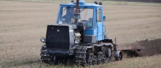
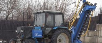
Plowing land MTZ-1221.2 + PLN-5-35.
Filmed 9/17/15. Plowing the land with a MTZ-1221.2 tractor with a PLN-4-35 plow converted to 5 furrows. Depth: ~ 25 cm. Plowing speed: ~ 8 km/h. Fuel consumption: ~20 l/ha. Productivity: 1-1.5 ha/h.
https://youtu.be/WDSYbiAqijk
Plowing land MTZ-1221.2 + PLN-5-35. Filmed 9/17/15. Plowing the land with a MTZ-1221.2 tractor with a PLN-4-35 plow converted to 5 furrows. Depth: ~ 25 cm. Plowing speed: ~ 8 km/h. Fuel consumption...youtu.be
Setting the depth
Adjustment of the plowing depth of the plow is established by the support wheels, and for plows intended for rocky soils - by the rear wheels.
In this case, the “Lifting” and “Floating” positions of the tractor hydraulic distributor are used, since in the neutral position the parts of the hydraulic system wear out .
To reduce tractor slipping, drive wheel loaders are used, if such are provided for in the design.
The action of the hydraulic loader is regulated by changing the oil pressure in the cavity of the power hydraulic cylinder on the rod side and focusing on the track of the plow support wheels. The oil pressure is selected so that the support wheels leave a shallow mark.
Such regulation of the depth of travel of a plow and other machines is called positional.
In addition to positional control, power control of the plow is known. With this method, the depth of the plow depends on the soil resistance . The plow support wheel is a hindrance and must be removed or lifted. Tractors are equipped with a special device included in the hydraulic system.
They produce two types of adhesion weight additional loaders, hydraulic and mechanical, for tractors of traction class 0.9.
There are a number of holes on the bracket for attaching the central link of the hitch mechanism to the tractor to change the attachment point of the upper link. The higher this point, the less the tractor slips, but the less stable the plow moves in depth .
In the same way, rearranging the height of the pins of the semi-mounted plow PLP-6−35 and the attachment points of the trailer to the plow frame has an effect. The lower this point, the greater the angle of inclination of the thrust line to the horizon, the lower the resistance of the plow, but the worse the running stability .
Tractor hitch T-150: diagram and principle of operation
31.01.2018
The tractor hitch is an important mechanism that requires proper maintenance and some attention. In this article we will fully analyze this element of “Vladimirets”, show its strengths and weaknesses that need to be paid attention to.
Mounting mechanism of the T-150K tractor
The tractor linkage mechanism is made according to a single lever-hinge design. Using a stand and a suspension axle, the machine is connected to the rear ends of three longitudinal links of the hitch, and the links, in turn, are connected to the tractor at three or two points by the front hinges.
T-150 hitch diagram
In order to understand the principle of operation of the T-150 tractor hitch, it is necessary to study its diagram; we have given it below with a detailed description.
a-hinging mechanism; 6 - fixing the hinged mechanism in the raised position; /-main cylinder; 2 - upper axis; 3 - thrust lever; 4 — locking finger; 5 — left lifting lever; 6-thrust ring; 7 — upper link crossbar; 8 — top link fork; 9 — lifting shaft of levers; 10 — right lifting lever; 11 — adjusting coupling of the upper link; 12 — upper screw of the brace; 13 — upper link clamp; 14—brace adjusting coupling; 15 — lower brace screw with left-hand thread; 16 - fork; 17—locking pin; 18 — ball of the spherical hinge; 19—lower link head; 20— lower link telescopic connection pin; 21 — tension screw; 22— extension coupling; 23 — extension screw with left-hand thread; 24 — chains of guy wires; 25 — lower link locking eye; 26 — lower link forks; 27 — extension chain earring; 28 — yoke of the lower axle with an eye; 29 — rod lever with locking hole; 30 — emphasis of the heads of the lower links; 31 — heads of lower links; 32- lower axis; 33 — frame bracket; 34 — lower axle bracket; 35 — longitudinal tie; 36 — rear axle mounting bracket; 37 — rod; 38 — thrust washer pin; 39 — shock absorber springs.
Three-point hitch scheme
Creates rigidity in connecting the machine to the tractor. With this hitch scheme, the tractor works with wide-cut machines, ensuring their stable, straight-line movement. The unit may only be turned with the machines raised to avoid their damage. The three-point hitch design is used, for example, to work with cultivators and seeders.
Two-point linkage
With it, the front ends of the lower links are located under the front end of the upper link. Due to this, free movement of the unit is achieved without digging out the working parts from the soil, not only in a straight line, but also with slight curves (at an angle of up to 20°). In addition, the two-point linkage allows you to move the hinges of the upper and lower links to the right of the tractor axis.
Mounted mechanisms of tractors T-150 and T-150K
They are designed in the same way; there are minor differences only in the attachment points of the mechanism parts to the tractor frame.
The linkage mechanism of the T-150K tractor is connected to its frame by two axles. The upper axis 2 (a) is fixed at its ends in the yokes of the upper part of the brackets 33 of the frame. The lower part of these brackets is connected to brackets 34, in the yokes of which the lower axis 32 of the hinge is clamped. Additionally, the bracket is attached by longitudinal ties 35 to the yokes 36 for attaching the rear post.
The main parts of the hitch are the lifting shaft 9, lifting levers 5 and 10, thrust lever 3, two braces (parts 12 and 16), three rods and two limiting chains 24. The lifting shaft rotates freely in the support bushings of axis 2, and the lifting arms are stationary mounted on its Christmas tree slots. At the bottom of the left lever 5 there is a platform into which the rod lever 29 rests. The lower groove of this lever fits into the head of the hydraulic cylinder rod and is connected to it with a pin. The thrust lever 3 rotates freely on the shaft 9 and can rest with its lower end against the upper flange of the spar of the rear semi-frame of the tractor.
When the rod extends from the hydraulic cylinder sleeve, lever 29 turns counterclockwise (up) and with its stop lifts the left 5, and through the shaft 9 and right 10 lifting levers. When the rod is retracted into the cylinder liner, the lever 29 rotates in the opposite direction (down), allowing the mounted machine to lower under the influence of gravity.
If you block levers 29 and 5 by placing a finger in their coaxial holes, then the machine will be lowered by the retracting movement of the hydraulic cylinder rod, and its working parts will be forced to deepen. To reliably hold a mounted machine in the transport position, for example, when moving at high speeds, you need to turn lever 3, align its upper hole with the holes of levers 29 and 5 and block these three levers with finger 4. Then the lower end of lever 3 will rest against the end of the frame tractor (b) and the raised machine will not lower.
The upper link is pivotally connected to the shaft 9 using a traverse 7 and a fork 8 and can be installed on the shaft along the axis of the tractor or with the necessary offset. The rod has a double-sided spring shock absorber. It improves the following of the terrain by the working parts of the machine and reduces shock loads. The shock absorber springs 39 are clamped through the washers by two fingers 38, which move freely in the elongated grooves of the rod head. Under the action of tensile forces transmitted from the mounted machine to the rod, the springs are compressed by the front washer, and under the action of pushing forces - by the rear washer.
The lower links are sliding, telescopic, locked with fingers 20. Ball joints are mounted in the rear heads of the three links for attaching the mounted machine.
The lower links are pivotally connected by braces to the lifting arms. The length of the brace can be adjusted by turning coupling 14. This adjustment achieves the required lateral tilt or horizontal position of the machine in the transverse plane. After adjustment, the coupling is locked with a nut.
The front ends of the lower links are pivotally connected to the axle 32 using forks 26 and heads 31. If these heads are located under the upper link, as shown in the figure, the hitch is installed in a two-point manner. In the transport position, the machine mounted in this way is kept from lateral swinging by two chain braces. Their length is adjusted using couplings 22 (when the machine is in a raised position) so that the lateral swing is within 10...20 mm in each direction. In this case, the adjusting screws 21 and 23, in order to avoid thread breakage, are not unscrewed by more than 40 mm.
To adjust the linkage mechanism according to the three-point scheme, the forks of the rods 26 with heads 31 are placed on the axis 32 in extreme positions. The stable movement of the wide-cut unit in the transverse direction is achieved by the same stretch marks, but adjusted to the length of free swing of the rod joints within the established limits.
To work with machines that require a rigid connection in the transverse direction, the lower links are blocked with guy wires; the front ends of the chains are attached crosswise to the eyes 25 and tensioned with couplings 22.
To operate the tractor with wide-cut machines that have support devices, a free play of the lower screw 15 in the fork 16 is installed in one of the braces. To do this, the locking male 17 is removed. Then the lower screw of the brace can move in the fork, allowing the machine to adapt to the terrain of the soil, but maintaining completed progress of working bodies in the soil.
Source
Main gear of the front drive axle Tractor MTZ 82
Regulator Tractor MTZ 82 R
Air cleaner starting engine Tractor MTZ 82 R
Drills for repair work (parameters)
Tags: rear linkage spare parts T-150K, spare parts T-150K, catalogue, linkage T150, article, T-150 Saransk, tractor T-150
Author: Administrator