Lesson plan 1. Driving a tractor - T-150 K. (Lesson 1). educational material on the topic
LESSON PLAN
Topic 1. Exercises in how to use tractor controls
Completion time: 2 hours.
Lesson objectives:
Educational: to develop practical experience in using the controls and instrumentation of the T-150 K wheeled tractor.
Educational: to cultivate interest in the profession of a tractor driver, conscientiousness, responsibility and work culture.
Developmental: develop technical thinking, independence, and the ability to use professional terminology in speech.
Lesson type: study of work techniques
Teaching method: visual, practical, individual
Material and technical equipment of the lesson:
Tractor T-150 K, tractor track, instructional and technological map, educational waybill, set of tools, set of refueling equipment, rags, first aid kit.
Intersubject communication: traffic rules, device, operation of the tractor.
During the classes
I. ORGANIZATIONAL POINT – 15 min
- Medical checkup.
- Checking the condition of workwear.
- Filling out the waybill.
II. INTRODUCTION TRAINING – 25 min
- State the topic and purpose of the lesson.
- Safety briefing.
- Demonstration of the conduct of ETO (conducted by a training master, the student monitors the conduct of ETO according to the instruction card “Procedure for conducting ETO”)
- Demonstration and demonstration of the exercise:
- showing the correct position of the tractor driver in the cab and the correct position of hands on the steering wheel;
- familiarization with tractor controls, pedals and instrumentation, detailed explanation of their purpose;
- demonstration of techniques for using hydraulic system levers;
- demonstration of techniques for using the gear shift lever;
- showing the location of filling tanks in the tractor;
- explanation and demonstration of starting methods for the main and starting engines;
- familiarization with the ITK of performing the exercise.
III. ONGOING INSTRUCTION – 45 min
The student independently, using the ITK, gets acquainted with the order of behavior of the ETO, with the location of the controls of the T-150 K wheeled tractor, the instrument panel, and starting the engine.
After familiarization, the master points with a pointer to the controls and main components of the tractor, and the student names the correct name and purpose of the controls and instrumentation, and also names the units of measurement of control readings (if necessary, filling containers and control readings). The student independently repeats the order of ETO behavior. Then he practices an exercise to start the engine.
IV. FINAL INSTRUCTION – 15 min
- Self-analysis and self-assessment of the student.
- Summing up the lesson, analyzing the execution of the exercise, indicating successes and shortcomings, difficulties that the student encountered.
- Assessing the student, placing a grade in a journal, an individual driving book, or a waybill.
- Homework: draw a panel of control and measuring instruments (in large form, preferably in paint)
Methodological recommendations for industrial training lessons
- Before performing the exercise, the student must undergo safety training.
- Before performing the exercise, it is necessary to carry out shift maintenance of the T-150 K tractor in accordance with the ITK in compliance with the ETO procedure.
- Independently, using the ITK, repeat the name, location, purpose of the controls and instrumentation of the tractor.
- Learn the procedure for performing the exercise and master the techniques for starting the starting and main engines.
- Start the engine in different ways.
- Familiarize yourself with proper seating and safe methods of ascending and descending into the tractor cab.
- Answer exam questions on the basics of road safety on the relevant topic.
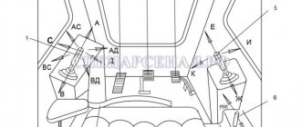
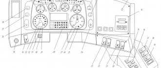
The controls of the T-150K wheeled tractor, control devices and alarms are shown in Fig. 5:
1 - fuse block. Installed inside the glove box;
2 - control lamp. Lights up green when the ground switch is turned on. When the generator starts working, the light from the lamp becomes weaker;
3—mass switch. By pressing the battery it is connected to the tractor ground, by pressing the side button it is disconnected;
4 - oil pressure indicator in the hydraulic system of the gearbox. Valid only when the engine is running;
5 — head of the windshield wiper control valve. The windshield wiper is turned on by turning the tap head counterclockwise. Rotating the head adjusts the windshield wiper speed;
6 - turn signal indicator lamp. Lights up flashing green when the turn signal is turned on;
7 — direction indicator switch. Moving the handle to the left turns on the left turn indicators, and moving it to the right turns on the right turn indicators. After completing the turn, it is necessary to move the handle to the neutral position;
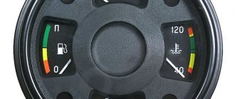
8 - two-pointer pressure gauge for monitoring air pressure in the pneumatic brake drive system. The arrow of the upper scale shows the pressure in the pneumatic system of the tractor, the lower scale shows the pressure of the air supplied to the brake chambers;
Rice. 5. Controls and monitoring devices of the T-150K tractor
9 — fan switch. When the handle is moved down, the blowing fan is turned on; when it is moved up, the dust separator fan is turned on;
10 and 11 - switches for the cabin lamp and headlights. The lamp and rear lights are turned on by moving the handle of the corresponding switch to the upper position;
12 — trachospeedometer. Shows the tractor speed (in km/h) on four concentric scales located at the top of the device (in accordance with the engaged gear of the transport row) and the crankshaft rotation speed on a scale located at the bottom of the device. The counter counts the engine operating time in hours.
13 — starter switch. The starter is turned on by turning the key clockwise until it stops;
14 — button to turn off the ignition of the starting engine (turned off by pressing the button);
15 — oil pressure indicator in the engine lubrication system (valid during engine operation);
16 - ammeter. Controls the charging and discharging mode of the battery;
17 — liquid temperature indicator in the engine cooling system;
18 — handle of the central light switch. The switch can be placed in one of three fixed positions:
- 0 — the handle is pushed in all the way, the lighting is off;
- 1 — the handle is half extended, the side lights or low beam headlights are on (depending on the position of the foot light switch);
- II - the handle is fully extended, the high or low beam of the headlights is turned on (depending on the position of the foot light switch).
By placing the handle in position I or II, the lighting of the instrument panels and rear marker lights are also turned on. Rotating the handle changes the brightness of the instrument lighting;
19 — steering wheel;
20 — sound signal button;
21 — lever for manual control of the main engine fuel pump. As the lever moves towards you, the fuel supply increases. The extreme forward position of the lever corresponds to stopping the fuel supply;
22 — lever for switching the rows of the transfer case and speed reducer. The diagram of its positions is shown in Fig. 6;
23 — button for checking the status of the warning lamps for emergency coolant temperature and emergency oil pressure in the lubrication system. When you press the button, the control lamp should light up red, which indicates its serviceability;
24 - warning lamp for emergency coolant temperature. Lights up red when the liquid temperature in the engine cooling system is 98-104 ° C;
25 - warning lamp for emergency pressure in the engine lubrication system. Lights up red when the oil pressure decreases to 1.9-1.3 kgf/cm2;
26 — gear shift lever. As the lever moves forward, gears are shifted sequentially from I to IV;
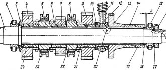
Rice. 6. Diagram of switching rows of the transfer case and speed reducer of the T-150K tractor.
27 - main engine radiator shutter control chain. When the chain is moved towards itself, the curtain closes the radiator honeycombs. The chain can be fixed in any position in the grooves of the guide sleeve;
28 - control chain for the carburetor air damper of the starting engine. When the rod moves towards you, the damper closes;
29 — lever for engaging the drive gear and clutch of the starting motor gearbox. When the lever is moved up (position I), the drive gear is engaged; when moved down (position II), the gearbox clutch is closed. In the neutral position of the lever (I), the gear clutch is always disengaged, and the drive gear is either on or off. The diagram of the lever positions is shown in Fig. 7;
30 — control handle for the fuel sump valve of the starting engine. When the handle is turned counterclockwise, the faucet opens;
31 — trailer independent braking lever;
32 — control levers for the distributor of the hydraulic system of the rear linkage;
33 — engine fuel pump control pedal. Interlocked with lever 21;
34 — brake valve control pedal;
35 — clutch control pedal;
36 - foot light switch. Designed to switch headlights from high beam to low beam or vice versa when setting the handle of the central switch 18 to position II and the low beam of headlights or front side lights to position I;
37 — lever for engaging the front axle drive. The bridge is activated by moving the lever forward;
38 — central (parking) brake lever;
39 — control lever for the hydraulic clutch of the PTO gearbox. The clutch is engaged by moving the lever up;
40 - lever for turning on the PTO gearbox drive, as well as the drive from the tractor wheels of the pumps of the hydraulic systems of the gearbox and steering. The diagram of the lever positions is shown in Fig. 8;
41 — lever for turning on the pump drive of the hydraulic system of the rear linkage. When the lever is moved forward, the pump turns on.
SAFETY WHEN WORKING ON THE T-150 K TRACTOR
- Before starting the engine, the gear shift lever and the mode shift lever must be in the “Neutral N” position, the hydraulic distributor levers of the attachments must be in the “Neutral” position; The parking brake is on.
- Before moving off, make sure that the path is clear and that there are no people between the tractor and agricultural implements, as well as in the area of the frame hinge. Warn about the start of movement with a sound signal.
- Before getting out of the tractor, set the gear shift lever and the mode shift lever to the “Neutral N” position; the hydraulic distributor levers of the attachments are in the “Neutral” position; set the parking brake and turn off the engine. To avoid overheating of the hydraulic system, do not leave the tractor in the position of full (all the way) rotation of the half frames to the right or left.
- When working with cables on tow hooks, it is prohibited to be in the radius zone of the cables.
- Do not use the parking brake when driving.
- It is prohibited to tow the tractor by the hitch mechanism.
- The folding ladders must be retracted while the tractor is operating.
- When driving a tractor with the hitch not fully raised, it is necessary to adjust the horizontal braces to a length that does not allow the hitch elements to touch the rear wings.
- Monitor the readings of control devices and their serviceability. It is prohibited to operate a tractor with faulty devices.
- It is prohibited to open the filler neck and expansion tank plugs or unscrew the steam-air valve in case of emergency overheating of the engine water.
- In the event of an accident or excessive increase in engine speed, immediately turn off the fuel supply using the stop handle.
- It is strictly forbidden to operate the tractor if the steering, brake system, electric lighting and alarm systems are faulty.
- All tractor control levers must be locked in the appropriate positions.
- The tractor brakes must be in good condition. When braking a tractor moving on dry and hard ground at a speed of 8.33 m/s (30 km/h), using the service brake, the braking distance should not be more than 13 m, at a speed of 5.6 m/s (20.2 km/ h) - no more than 6.5 m. The fully depressed brake pedal should not rest against the floor of the cabin.
- The air pressure in the brake pneumatic system during operation should be 0.65 - 0.8 MPa (6.5 - 8.0 kgf/cm2).
- Batteries must be securely fastened, covered with a lid and must not leak electrolyte.
- Before turning on the “ground” switch after parking the tractor for a long time (more than a day), especially in the summer, open the lid of the battery container for at least 5 minutes. to remove the explosive hydrogen-air mixture formed during the self-discharge process.
- Monitor the condition of electrical equipment. Sparking, breakage of wires and terminals, especially near heated parts and in places where oil and fuel may come into contact with them, are unacceptable.
- The permissible tractor speed on access roads and driveways is no more than 2.77 m/s (10 km/h).
- When turning, choose a speed that ensures safe driving. It is prohibited to make a sharp turn higher than in the first gear of the fourth mode.
- When crossing dams, roads and bridges, make sure you can pass and only use reduced speeds.
- Before overcoming sections of the road that require movement on both drive axles (lifting, difficult to pass places), engage the rear axle in advance.
- When working on slopes, be careful and careful when driving the tractor and comply with the following conditions:
- do not turn off the engine or change gears and modes on steep ascents and descents;
- When driving downhill, it is prohibited to use coasting;
- across a slope (the slope should not exceed 5 degrees) it is allowed to work only in modes I…II and avoid sharp turns and moving over obstacles.
- Ford a water crossing only after careful preparation and check of the route. It is allowed to overcome a ford with a depth of no more than 0.8 m (for the K-744R2 tractor - 1.0 m).
- Hitching to a tractor and mounting agricultural machines and implements on a tractor must be carried out by persons servicing these machines. The trailer hitching the machine must stand aside until the tractor comes to a complete stop and begin coupling (hitching) only after the driver’s signal.
- When operating a tractor with agricultural machines and implements, follow the safety rules set out in the operating instructions for this machine or implement.
- Drive the tractor up to agricultural machines, implements or trailers at the lowest speed with the drain valve drive pedal not fully depressed, after sounding the sound signal.
- After connecting to trailed implements and bleeding the hydraulic system, check the oil level in the hydraulic tank and top up if necessary.
- Move the tractor with mounted and semi-mounted machines in the transport position with preliminary fixation of the mounted device by means of hydromechanical valves of the hydraulic cylinders. When closing hydromechanical valves, the parking brake must be applied. Standing under a raised agricultural implement is strictly prohibited.
- When stopping for a long time, do not leave the agricultural implement in a raised position. It is strictly prohibited to stand under a raised weapon.
- When working with hydraulically powered agricultural machines and implements, it should be remembered that the maximum operating pressure at the outlet of quick-connect breaking devices is at least 15.0 MPa (150 kgf/cm2).
- Move with mounted machines over ditches, hillocks and other obstacles at a right angle at low speed, avoiding sudden jolts and large rolls of the tractor.
- It is prohibited to drive trailed implements, mounted machines and outside the tractor cab that are not equipped for this purpose.
- Trailed implements and trailers must have rigid couplings that prevent them from running into the tractor.
- When disconnecting the tractor from trailed implements or trailers, first disconnect the pneumatic systems and electrical equipment.
- Only persons who know the rules for working with them are allowed to work with trailers, semi-trailers and other vehicles.
- When aggregating with trailers and semi-trailers, attach their safety chains to the connecting links located on the linkage arms of the hitch.
When using the tractor for transport work, the following precautions must be taken:
- carry out work with the “Road Train” sign on; check the reliability of the pneumatic system;
- pay special attention to the choice of driving speed, taking into account road conditions, turning radii, visibility, features and condition of vehicles and cargo being transported;
- on snowy, waterlogged and other roads with a low coefficient of adhesion, as well as on slopes, turns, slopes, icy conditions, etc. drive at reduced speeds, avoid sudden braking and turning;
- When driving on roads with a low coefficient of adhesion, it is recommended to drive the transport train “stretched” - to do this, first of all brake the aggregated vehicle by moving the manual brake valve to an intermediate position 10 fig. 3, and then use the tractor service brakes;
- if a danger to traffic arises, take measures to reduce the speed and stop the transport train;
- In the event of an unexpected stop of the tractor on the roadway, turn on the hazard warning lights.
- trailer brakes must be adjusted in accordance with the requirements of the trailer operating instructions;
- a tractor train is allowed to move at a maximum speed of 8.39 m/s (30 km/h) only on roads with dry hard surfaces;
- in order to avoid increased wear of the brake mechanisms of trailers, long-term operation of a transport train with braked trailers is not recommended;
- at the first signs of folding or skidding of the transport train, release the brake pedal and brake using the trailer brake control handle until the folding or skidding is eliminated;
- When parking a tractor train, when loading (unloading) trailers, set the handle of the hand brake valve to the “pull” position. Before starting to move, set the brake valve handle to the “away” position;
- when connecting a tractor to vehicles with 12-volt equipment, it is necessary to replace the vehicle's electric lamps;
when driving with a vehicle:
- periodically check the functionality of the trailer brakes by braking it with the trailer brake control handle;
- It is prohibited to use the manual fuel supply lever; set the fuel supply lever to the minimum fuel supply position;
- Transporting people on trailers is prohibited.
- Do not operate the power take-off mechanism without installing all protective covers. During short stops to inspect a unit that operates with a power take-off shaft, it is necessary to turn off the power take-off shaft.
Engine
The product of the Kharkov Tractor Plant received a power plant manufactured by the Yaroslavl OJSC Avtodizel. The 11.15-liter YaMZ-236D-3 engine has a power of 128.7 (175) kW (hp) and a rotation speed of 2100 rpm.
The 6-cylinder four-stroke diesel engine features a V-shaped cylinder arrangement, direct injection, and liquid cooling. Ignition in the unit occurs from compression. Functionally, the YaMZ-236D-3 is equipped with a torsional vibration damping system.
Thanks to the installed pre-heater, the HTZ-150K will not have any special problems with starting the engine in the cold season. These features make the tractor a serious competitor to rivals in its category.
Schematic diagram of the electrical equipment of the T-150K tractor
Detailed explanation with photos, electrical diagram of fuse and relay blocks for Tractor cars.
1 - generator; 2 — sound signal; 3 — front headlight; 4 — engine start blocking switch; 5 — water temperature indicator sensor; 6 — sensor for emergency temperature indicator in the engine cooling system; 7 — sensor for emergency oil pressure indicator in the engine lubrication system; 8 — air cooler blocking sensor-relay; 9 — plug connector; 10, 11 — fuse blocks; 12 — sound signal button; 13 - direction indicator warning lamp; 14 — direction indicator switch; 15 — direction indicator breaker; 16 — electric motor for blowing the tractor driver; 17 — electric motor for cabin ventilation; 18 — fan switch; 19 — dome lamp switch; 20 — lampshade; 21 — rear headlight switch; 22 — starter switch; 23 — magneto push-button switch; 24 — rear light (brake light, turn signal, side lights); 25 — brake light switch; 26 — trailer socket; 27 - central light switch; 28 — license plate light; 29 — warning lamp for emergency water temperature in the engine cooling system; 30 — switch for monitoring the emergency state of lamps; 31 — water temperature indicator; 32 — instrument lighting lamps; 33 — oil pressure indicator in the engine lubrication system; 34 — rear headlight; 35 — foot light switch; 36 — portable lamp; 37 - ammeter; 38 — warning lamp for emergency oil pressure in the engine lubrication system; 39 — control lamp for turning on the “mass”; 40 — “mass” switch; 41 — tachometer; 42 - battery; 43 — oil pressure indicator in the gearbox hydraulic system; 44 — two-pointer air pressure gauge; 45 — plug connector; 46 — plug socket for turning on a portable lamp; 47 - relay regulator; 48 — front lamp; 49 — starter; 50 — spark plug for starting engine; 51 - magneto. A - terminal for connecting the air cooler relay; B — terminal for connecting the air cooler contactor; D - terminal for connecting electrical equipment of the preheater; G - terminal for connecting the air cooler fan switch.
On the website avto-fresh.com you can find a schematic diagram of the electrical equipment of the T-150k tractor, photo and description of the units, as well as answers to questions about where it is located and what it is responsible for. The designation of electrical equipment is described in detail in the article.
Device and attachments
The main advantage of the HTZ-150K is considered to be a 3-range gearbox, which allows you to switch between gears while driving or carrying out work. The clutch model is a dry double-disc clutch. Thanks to an independent 2-speed power take-off shaft (540 and 1000 rpm), the tractor is compatible with an impressive number of agricultural implements: – row-crop plow; – a bulldozer shaft for clearing snow, leveling the ground or removing dirt; – railway automatic coupler used on rail tractors; – a trailer with the ability to transport 20-ton loads; – harrow; – cultivator; - seeder.
HTZ-150K has hydrostatic steering, wheel shoe brakes with a pneumatic drive on each wheel and a band parking brake with a pneumatic spring cylinder. In the standard version, the tractor is equipped with 4 single wheels. When placed in a double position, the HTZ-150K is equipped with 8 wheels.
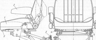
The modernized design of the tractor operator's cabin maintains comfortable working conditions for the driver. There have been many improvements in comparison with previous models. Thus, the location of buttons and control levers has been optimized, and thermal and noise insulation has been increased. The operator's cabin in the HTZ-150K is panel, closed, with two seats: an unsprung passenger seat with a backrest adjustable for inclination, and a sprung driver's cabin with a hydraulic shock absorber, height and weight adjustment and variable backrest tilt. Large operator cab windows and mirrors provide good visibility.
Comfort can safely be called a distinctive quality of the HTZ-150K. Previously, domestic models in this parameter were far behind their foreign counterparts. In HTZ-150K the backlog is almost completely eliminated.
Upon request, the model is equipped with an automatic hitch control system and air conditioning, which improves working conditions, reduces fuel consumption by 6% and increases productivity by 8-10%.
Specifications
- HTZ-150K is equipped with a YaMZ-236D-3 engine with a power of 128.7 hp.
- The specific fuel consumption of the model is 220 (162) g/kW. per hour (g/hp per hour).
- With relatively low fuel consumption, the tractor has a large fuel tank of 315 liters, which has a positive effect on the battery life of the model.
- Dimensions HTZ-150K: height – 3195 mm, length – 6130 mm, width – 2406 mm.
- The tractor has a mass of 8200 kilograms.
- The wheelbase of the HTZ-150K is 2860 mm, the turning radius is 6500 mm. The ground clearance of the model is 400 mm.