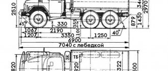
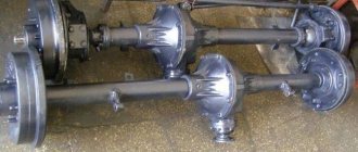
Front and rear axles 151.72.001-5A and 151.73.001-5A - T-150K:
151.72.001-5A 151.73.001-5A 1 1 2 3 4 4 5 6 7 8 9 10 11 12 13 14 15 16 17 18 19 20 21 22 23 24 25 26 27 28 29 30 31 32 33 3 4 35 36 37 38 39 40 41 42 43 44 45 46 47 48 49 50 51 52 53 54 55 56 57 58 59 60 61
List of components from Front and rear axles 151.72.001-5A and 151.73.001-5A on T-150K
Parts diagrams are for reference purposes only! We do not sell all spare parts from Front and rear axles 151.72.001-5A and 151.73.001-5A for the T-150K presented in this list. If there is a link “Show prices” in the right column, these spare parts from “Front and rear axles 151.72.001-5A and 151.73.001-5A” are on sale. Availability in warehouses for details and prices, see the product card. If there is no “Show cost” link in the right column, we do not sell such parts and do not accept orders for them.
| № | Part code | Name | Part Information | Show all prices |
Transmission of the T-150 tractor
The difference between the T-150 tractor gearbox and similar components of similar agricultural machines is the presence of two brake shafts, which are intended for movers on the left and right. This is a way to change the speed and traction of a machine and a means of turning the tractor in any radius. For the wheeled and tracked modifications of the T-150 model, the gearboxes are unified and work with the main drive in the form of planetary gearboxes.
Crawler tractors are equipped with a double-flow gearbox with transmission distribution to a specific caterpillar. For wheeled ones (T-150K), traction force is transmitted to the drive axles via a transfer case. The gearbox also includes a PTO for controlling attachments.
When changing gears, the pressure in the working cylinders must be maintained in the gearbox. For this purpose, during the development of technology, hydraulic accumulators were added, consisting of a housing, a cover, a piston and a spring.
Not available:
| № | Part code | Name | Part Information |
| 151-72-001-5A | Front axle | Quantity per T-150K 1 | Not available |
| 151-73-001-5A | Rear axle | Quantity per T-150K 1 | Not available |
| 151-72-011-5 | Main transmission assembly | Quantity for T-150K 2 Included in 151.72.001-5A | Not available |
| 151-72-011-5 | Main transmission assembly | Quantity for T-150K 2 Included in 151.73.001-5A | Not available |
| 151-72-012 | Front axle housing assembly | Quantity for T-150K 1 Included in 151.72.001-5A | Not available |
| 151-73-012A | Rear axle housing assembly | Quantity for T-150K 1 Included in 151.73.001-5A | Not available |
| 151-72-013-5 | Main gear differential assembly | Quantity for T-150K 2 Included in 151.72.011-5 | Not available |
| 151-72-020-1 | Satellite with bushing assembly | Quantity for T-150K 8 Included in 151.72.013-5 | Not available |
| 151-72-162-1 | Differential box flange | Quantity for T-150K 4 Included in 151.72.013-5 | Not available |
| 151-72-211-1 | Friction disc | Quantity for T-150K 4 Included in 151.72.013-5 | Not available |
| 151-72-212-1 | Leading friction disk | Quantity for T-150K 8 Included in 151.72.013-5 | Not available |
| 151-72-216-2 | Axle coupling | Quantity for T-150K 4 Included in 151.72.013-5 | Not available |
| 151-72-218 | Centering friction disk | Quantity for T-150K 4 Included in 151.72.013-5 | Not available |
| 151-72-225 | Hairpin | Quantity for T-150K 32 Included in 151.72.001-5A | Not available |
| 150-38-103-1 | Drive gear | Quantity for T-150K 2 Included in 151.72.011-5 | Not available |
| 150-38-104-1 | Driven gear | Quantity for T-150K 2 Included in 151.72-011-5 | Not available |
| 150-38-108-1 | Pad | Quantity for T-150K 2 Included in 151.72.001-5A | Not available |
| 125-72-015 | Final drive housing cover assembly | Quantity for T-150K 2 Included in 151.72.011-5 | Not available |
| 125-72-016-1 | Final drive housing assembly | Quantity for T-150K 2 Included in 151.72.011-5 | Not available |
| 125-72-019 | Breather assembly | Quantity for T-150K 2 Included in 151.72.001-5A | Not available |
| 125-72-102-1 | Final drive housing assembly | Quantity for T-150K 2 Included in 125.72.010-1 | Not available |
| 125-72-105 | Differential bearing cover | Quantity for T-150K 4 Included in 125.72.016-1 | Not available |
| 125-72-106A | Left differential box | Quantity for T-150K 2 Included in 151.72.013-5 | Not available |
| 125-72-107A | Differential box right | Quantity for T-150K 2 Included in 151.72.013-5 | Not available |
| 125-72-110 | Axle bearing cup | Quantity for T-150K 2 Included in 151.72.011-5 | Not available |
| 125-72-111-1 | Drive gear flange | Quantity for T-150K 2 Included in 151.72.011-5 | Not available |
| 125-72-112 | Main gear housing cover | Quantity for T-150K 2 Included in 125.72.015 | Not available |
| 125-72-113 | Oil removal ring | Quantity for T-150K 2 Included in 151.72.011-5 | Not available |
| 125-72-114 | Drive gear washer | Quantity for T-150K 2 Included in 151.72.011-5 | Not available |
| 125-72-120 | Main pair adjusting gasket | Included in 151.72.011-5 Note 3 | Not available |
| 125-72-121 | Main pair adjusting gasket | Included in 151.72.011-5 Note 3 | Not available |
| 125-72-122 | Spacer ring | Included in 151.72.011-5 Note 3 | Not available |
| 125-72-124 | Bearing adjusting gasket | Included in 151.72.011-5 Note 3 | Not available |
| 125-72-125 | Bearing adjusting gasket | Included in 151.72.011-5 Note 3 | Not available |
| 125-72-126 | Ring 155-160-36-2-4 GOST 9833-73 | Quantity for T-150K 4 Included in 151.72.011-5 | Not available |
| 125-72-131 | Support washer for satellite | Quantity for T-150K 8 Included in 151.72.013-5 | Not available |
| 125-72-132 | Differential bolt | Quantity for T-150K 16 Included in 151.72.013-5 | Not available |
| 125-72-136 | Adjusting nut | Quantity for T-150K 4 Included in 151.72.011-5 | Not available |
| 125-72-137 | Hairpin | Quantity for T-150K 8 Included in 125.72.016-1 | Not available |
| 125-72-146 | Lock washer | Quantity for T-150K 4 Included in 151.72.011-5 | Not available |
| 125-72-147 | Lock washer | Quantity for T-150K 4 Included in 151.72.011-5 | Not available |
| 125-72-155 | Differential pin | Quantity for T-150K 4 Included in 151.72.013-5 | Not available |
| 125-72-170 | Locking plate | Quantity for T-150K 12 Included in 151.72.011-5 | Not available |
| 125-72-171 | Tightening bolt | Quantity for T-150K 24 Included in 151.72.011-5 | Not available |
| 5-22-241 | Adjusting bolt | Quantity for T-150K 4 Included in 151.72.011-5 | Not available |
| A02-35 | Cylindrical pin | Quantity for T-150K 2 Included in 151.72.001-5A | Not available |
| Cuff-1-75x100-4-GOST-8752-70 | Cuff 1-75x100-4 GOST 8752-70 | Quantity for T-150K 2 Included in 125.72.015 | Not available |
| Bearing-7313-GOST-333-71 | Bearing 7313 GOST 333-71 | Quantity for T-150K 2 Included in 151.72.011-5 | Not available |
| Bearing-7517K-GOST-333-71 | Bearing 7517K GOST 333-71 | Quantity for T-150K 4 Included in 151.72.011-5 | Not available |
| Bearing-7614-GOST-333-71 | Bearing 7614 GOST 333-71 | Quantity for T-150K 2 Included in 151.72.011-5 | Not available |
| Bolt-M8-6gх20-66-GOST-7796-70 | Bolt M8-6gх20.66 GOST 7796-70 | Quantity for T-150K 8 Included in 151.72.011-5 | Not available |
| Bolt-М12-6gх55-88-35-GOST-7795-70 | Bolt М12-6gх55.88.35 GOST 7795-70 | Quantity for T-150K 12 Included in 151.72.011-5 | Not available |
| Nut-M12-7N-6-GOST-5915-70 | Nut M12-7N.6 GOST 5915-70 | Quantity for T-150K 4 Included in 151.72.011-5 | Not available |
| Gayka-M14x1.5-7N-6-GOST-5915-70 | Nut M14x1.5-7N.6 GOST 5915-70 | Quantity for T-150K 32 Included in 151.72.001-5A | Not available |
| Nut-M12x1.25-6N-8-GOST-2524-70 | Nut M12x1.25-6N.8 GOST 2524-70 | Quantity for T-150K 24 Included in 151.72.011-5 | Not available |
| Nut-M20x1.5-6N-8-GOST-5932-62 | Nut M20x1.5-6N.8 GOST 5932-62 | Quantity for T-150K 8 Included in 125.72.016-1 | Not available |
| GKN-2M30 | Low slotted nut | Quantity for T-150K 2 Included in 151.72.011-5 | Not available |
| Washer-12-65G-GOST-6402-70 | Washer 12.65G GOST 6402-70 | Quantity for T-150K 12 Included in 151.72.011-5 | Not available |
| Washer-14-65G-GOST-6402-70 | Washer 14.65G GOST 6402-70 | Quantity for T-150K 32 Included in 151.72.001-5A | Not available |
| Cotter pin-4x32-GOST-397-66 | Cotter pin 4x32 GOST 397-66 | Quantity for T-150K 8 Included in 151.72.011-5 | Not available |
| Cotter pin-6x60-GOST-397-66 | Cotter pin 6x60 GOST 397-66 | Quantity for T-150K 8 Included in 125.72.016-1 | Not available |
| Cotter pin-6.3x50-GOST-397-66 | Cotter pin 6.3x50 GOST 397-66 | Quantity for T-150K 2 Included in 151.72.011-5 | Not available |
| PMM-39-B | Magnetic plug assembly | Quantity for T-150K 2 Included in 151.72.001-5A | Not available |
| KU-39 | Sealing ring | Quantity for T-150K 2 Included in 151.72.001-5A | Not available |
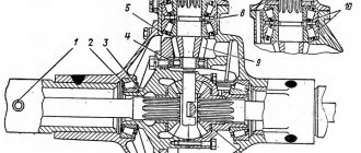
Rice. 2. Main gear: 1 — drive gear; 2, 6, 23 — tapered roller bearing; 3—body; 4 - glass; 5, 16—adjusting gasket; 7, 15, 26, 30, 31 — bolt; 8 — oil seal housing; 9—oil deflector washer; 10, 28— flange; 11, 33 - nut; 12—felt boot; 13 — dust-removing ring; 14 — frame oil seal; 17, 19 — sealing ring; 18 — remote bushing; 20—driven gear; 21 - finger; 22—satellite; 24 — adjusting nut; 25 — locking plate; 27—cover; 29, 32•—cup; 34 — hairpin; 35 — semi-axial gear; 36, 37 - disk.
There are linings welded to the front axle housing on top on both sides, which serve as supports for the spring mounting stepladders.
Brackets with holes for mounting bolts to the frame are welded to the rear axle housing.
On tractors of early production, the brackets were not welded, but in the upper right part of the crankcase, strips were welded that determined the transverse position of the bridge.
The basis of the bridge - the crankcase, consists of two halves - upper and lower, stamped from sheet steel and welded together with two longitudinal seams.
At the point where the main gear is attached, the middle part of the crankcase is expanded and its rigidity is increased due to a welded flange, in which a centering bore is made and threaded holes are provided for studs 9 for fastening the main gear housing.
In the place opposite the main gear mounting socket, the crankcase hole is closed with a welded convex stamped cover, oil filler holes closed with a threaded plug; The magnet in the plug serves to catch metal particles from the oil bath.
A breather is screwed into the threaded hole in the axle housing.
The main gear is assembled in a cast ductile iron housing.
The gear part of the main gear consists of a pair of spiral bevel gears.
The main gear drive gear, manufactured integrally with the shaft, is mounted on two tapered roller bearings in a cup, centered relative to the housing and bolted to it.
The inner race of the bearing is seated on the journal of the gear shaft, rests against its collar, and the outer race is installed in the cup seat and also rests against the collar.
To prevent lubricant seepage between the body and the glass, a rubber sealing ring is installed in the annular groove of the latter.
Between the inner races of the tapered bearings on the gear shaft there is a spacer sleeve and a set of spacers that serve to regulate the total axial clearance in the 2 and 6” bearings.
The splined shank of the gear shaft is fitted with a flange with four holes for bolts, designed for connection to the axle drive cardan. Between the ends of the inner race of the bearing and the flange there is an oil deflector washer with an oil drain thread made on its outer surface.
The set, placed on the bevel gear shaft, is tightened with a castle nut screwed onto the threaded shank of the shaft; the nut is secured with a cotter pin.
The glass and seal housing are attached to the housing with six bolts secured with spring washers. To seal the joint between the flange surfaces of the body and the glass, a rubber sealing ring is installed in the annular groove made in the glass. The position of the cup with bearings and gear relative to the housing is regulated by a set of gaskets.
To remove the cup during adjustments or disassembly, two bolts are used, screwed into the threaded holes of the cup flange and secured with locknuts.
A frame self-clamping oil seal and a felt boot are pressed into the oil seal housing. A stamped dust ejection ring is welded to the flange, which, together with the surface of the seal housing, forms a labyrinth that prevents dust from reaching the edge of the boot.
The driven bevel gear is attached with twelve special semi-fitted bolts to the differential housing shoulder and rotates together with it on two roller bearings with tapered rollers. The outer races of the bearings are installed in seats, each of which is formed by a housing and a cover; From the end, the outer races of the bearings are pressed with adjusting nuts. The bearing housings 23 and the threads for the nuts are machined in the housing together with the covers, so the covers cannot be replaced or swapped.
Each cap is secured to the body with two studs screwed into the body and castle nuts. The nuts are kept from being loosened by locking plates attached to the covers with bolts.
The automatic locking differential is assembled in a housing consisting of two flanges, a cup and a cup with a collar secured with bolts and castle nuts.
The differential consists of four bevel gears rotating on two pins and two bevel axle gears. Four steel friction disks are installed between the ends of the latter and the flanges. The disks, with their external splines, are connected to the splines of the flanges, and the disks, with their internal splines, are connected, like the semi-axial gears, to the axle shafts.
With the same resistance to movement of the tractor wheels and the same angular velocity, the satellites remain motionless relative to the pins, and the torque is distributed equally between the wheels. With unequal resistance to movement, the satellites begin to rotate on their fingers. An axial force arises in the gearing, which, acting on the semi-axial gears, compresses the friction disks and through them blocks the gears with the differential housing, and therefore with the driven semi-axial bevel gear. The amount of blocking is proportional to the difference in resistance to movement of the drive wheels.
Both fingers are clamped in the sockets formed by the cups.
Finger nests are formed when both cups are processed together, and therefore the latter cannot be steamed or their relative positions changed.
To ensure the correct relative position during assembly and to avoid uncoupling, numbers from 001 to 1000 are stamped on both differential cups. During assembly, the cups must be installed so that the numbers are the same and located next to each other.
For better lubrication of the fingers, flats are made in the places where the satellites are put on them.
Housing 3, assembled with the main gear, is centered by a shoulder relative to the bore of the rear axle housing and is attached to the latter with seventeen studs with nuts and locked spring washers. To seal between the flanges of the rear axle housing and the final drive housing, a paronite gasket is installed.
On older tractors, the main gear housing was fastened to the axle housing with sixteen pins, and was kept from turning by a pin pressed simultaneously into the flanges of the axle housing and the main gear housing.
Wheel gearboxes serve to convert and transmit torque from the driven gears of the main gears to the tractor wheels. They are planetary-type mechanisms attached to the flanges of the axle housings.
The wheel reducer is mounted on a forged steel hub shaft, attached with eight bolts to the axle housing flange. The hub shaft is kept from turning by two precision pins pressed into the holes of the hub and flange. The brake shield is sandwiched between the hub and axle flanges.
The drive gear of the planetary gear set is the sun gear, the driven part is connected to the tractor wheel, the carrier with three gears (satellites), and the braked stationary gear, which receives the reactive torque, is the epicyclic gear.
The sun gear is mounted on the splines of the axle shaft with a stop in the collar and secured with a nut locked by a bending plate. The axle shaft is a hardened steel rod with a splined shank that fits into the splines of the differential side gear.
The front (right and left) and rear (right and left) wheel gearboxes differ from each other only in the length of the axle shafts.
The longest axle shaft is the front left, then the rear left, the shortest is the front right.
The axle shaft assembly with the sun gear does not have bearings, but is freely installed; its position is determined by the teeth of three satellites meshed with the sun gear.
The support of the planetary gear is the carrier with satellites, which are installed in the grooves of the carrier.
The satellites rotate on axles hardened to high hardness, pressed into sockets bored into the carrier. The satellite bearings are cylindrical rollers, arranged in two rows of thirteen in each row. Both rows of rollers are separated by a washer. One track of the rollers is the ground surface of the axle, and the other is the ground surface of the satellite.
Rice. 3. Wheel reducer: 1 - sun gear; 2, 4, 9 — sealing gaskets; 3 - carrier; 5 - epicyclic gear; « — gear housing; 7 — spring ring; 8 — wheel disk; 10, 20, 22, 25, 37—nuts; 11, 14 — tapered roller bearings; 12 — gear housing; 13 — brake shield; 15 — hub shaft; 16 - bolt; 17 — axle shaft; 18, 19 — pins; 21 — lock washer; 23 — brake drum; 24 — hub; 26 — bar; 27 — hairpin; 28 — roller; 29 — satellite axis; 30—satellite gear; 31 - conical drain plug; 32, 33 — washers; 34 - shaped plate; 35— cover; 36 - control plug.
The satellites and rollers are kept from moving in the axial direction by washers.
The satellite axes are held in the carrier sockets on the inside by strips, each of which is attached to the carrier with two bolts, and on the outside by a shaped plate attached to the carrier by three bolts. The plate also serves to limit the transverse movement of the axle shaft together with the sun gear.
The carrier is attached to the body by means of twenty-one studs with nuts and spring washers. The carrier is centered by a shoulder that fits into the body bore. On the carrier flange, in addition to twenty-one holes for studs, there are also two threaded holes for conical drain plugs, coinciding with the holes in the housing flange
On the carrier there is a machined flange with twelve threaded holes, to which a stamped cover with a threaded hole in the center for a control plug is pressed with twelve bolts. Between the carrier and the cover, as well as the carrier and the body, sealing gaskets are installed.
The housing is centered and pinned to a housing that rotates on two tapered roller bearings supported by the hub shaft.
The brake drum and drive wheel disk are attached to the body with the same studs.
To securely tighten the package, which consists of four parts, the pin connection is made in a special way. A collar with flats on the stud, which fits into the annular groove of the body, keeps the studs from turning. The body and crankcase are tightened with nuts, which are secured to prevent loosening.
In this case, a sealing gasket is clamped between the housing and the crankcase. On the opposite side, a brake drum and a wheel disk, the holes of which have conical chamfers, are put on the studs. The brake drum and wheel disc are secured with nuts to the housing flange. The cones of the nuts entering the conical chamfers of the wheel disk center the latter and are locked by friction of the conical surfaces.
Thus, the driven unit, consisting of a carrier with satellites, a housing, a crankcase, a brake drum and a drive wheel, rotates on the bearings. The outer races of the bearings are installed in the bores of the crankcase with a stop in the collars, the inner race of the bearing is installed on the neck of the hub shaft with a stop in its collar, and the inner race of the bearing is seated on the neck of the gear hub, put on the splines of the hub shaft. The hub can move along the splines to the extent necessary to adjust the tapered roller bearings. The nut and locknut serve to adjust the bearings and hold the hub axially. A ground washer is installed between the nut and the locknut.
An epicyclic gear is mounted on the hub gear, which can move within certain limits relative to the hub teeth due to gaps in the tooth connection, and its position in space is determined by simultaneous engagement with three satellites. The epicyclic gear is kept from moving in the axial direction relative to the hub by two wire spring rings inserted into the annular grooves.
The seal of the internal cavity of the wheel reducer is an end seal, installed at the junction of the rotating crankcase and the stationary hub shaft.
The rotating part of the mechanical seal is bolted to the crankcase and includes a seal housing, a rubber diaphragm, tightly secured to the pressure ring using a press-on retaining ring and an outer labyrinth ring.
A sealing gasket is installed between the seal housing and the crankcase, and the diaphragm is sandwiched between the flange and the outer labyrinth ring. Eight spiral springs are installed in the pressure ring sockets, which rest against the bottoms of the seal housing sockets and constantly push back the pressure ring suspended on the diaphragm, pressing it against the thrust ring mounted motionless on the hub shaft.
The pressure ring is kept from rotating by two pins pressed into the seal body and inserted into the holes of the pressure ring, without limiting its movement in the axial direction.
Rice. 4. Mechanical seal: 1 - gear housing; 2 - springs; 3 - sealing gasket; 4 - bolt; 5 — seal code; 6 — rubber diaphragm; 7 - pressure ring; 8 — fastening ring; 9—inner labyrinth ring: 10, 15—pins; 11 — hub shaft: 12 — rubber ring; 13 — thrust RING; 14 - Outer labyrinth ring.
The stationary part of the seal is a thrust ring, a rubber ring and an internal labyrinth ring. All these parts are installed on the hub shaft. The ring is kept from turning by a pin pressed into the hub and inserted into a hole on the outer surface.
The action of the seal is that the rings are pressed against each other by springs and, in contact with their ground ends, do not allow lubricant to pass out of the final drive cavity.
Lubrication system. The front and rear drive axles and both wheel gears have a common oil bath with a level corresponding to the lower edge of the hole for the inspection plug. The cavities of the wheel gearboxes and the main gear communicate through holes in the hub shafts and have a common breather.
Drive axles with wheel reduction gears are filled with tractor transmission oil.
In tractors of early production, the cavities of the wheel gearboxes and main gears were separate and sealed with self-clamping frame oil seals installed in the hub shafts, and rubbing their working edges against the surface of the ground journals of the axle shafts.
The oil level in the wheel gears was determined by a dipstick attached to the plug, and the level in the axle cavity was determined using the control plug. It is recommended to remove the oil seals from the hub shafts on all early production tractors and determine the overall oil level by the edges of the holes for the control plugs.
Maintenance of axles and wheel gears, adjustments
To ensure proper operation of both bridges, the following rules must be observed. 1. Check the oil level in a timely manner in accordance with the lubrication chart and, if necessary, add it, as well as change the oil. 2. During operation, monitor the tightening of the nuts securing the main gears to the axle body, bolts securing the wheel reducers, nuts securing the wheel disks and other fasteners. 3. Monitor the appearance and promptly eliminate leaks. 4. If noise appears in the main gears, as well as during maintenance No. 3, check the axial movements of the drive gears of the main gears and, if necessary, adjust the clearance in the tapered bearings of the drive gears of the main gear. 5. Periodically check the clearance in the tapered roller bearings of the final drives and, if necessary, adjust it. 6. After 960 hours, check the correct installation of the rear axle and, if necessary, adjust it. Correct installation of the rear axle ensures the longevity of the crosspieces and bearings of the rear double fork of the cardan transmission, as well as the intermediate support.
Adjusting the main gear drive gear bearings. The clearance in the bearings of the drive gear is checked using a device with an indicator, moving the drive gear in the axial direction from one extreme position to another. If the device is not available on the farm, the need to adjust the bearings is checked by shaking the drive gear by the cardan flange in the radial and axial directions.
If the drive gear moves too freely in the tapered bearings, they should be adjusted.
To adjust the clearance in the bevel bearings of the drive gear, you must: 1. Disconnect the propeller shaft flange by unscrewing the four nuts and removing the bolts from the flange. 2. Unscrew the six bolts securing the cup to the main gear housing. 3. Screw in two long bolts like pullers and press out the glass. 4. Without disassembling the glass, check that the set of shims is installed correctly between the bearings. To do this, clamp the flange of the cup, and undo the pinion shank nut and tighten it until it stops. If there are more spacers than required, drive gear I rotates freely behind the flange, and its movement in the bearings is felt. If there are not enough shims, tightening the nut causes the bearings to overtighten, causing the drive gear to turn very slowly or not at all. In this case, it is necessary to adjust the bearings, that is, to correctly select the thickness of the set of shims, for which the shims are added in several stages so as to obtain the required tension in the bearings. 5. Unscrew the nut, remove the flange, the housing cover with oil seals, the oil flinger washer and the outer bearing with the inner ring. 6. Remove or add, depending on need, one or more gaskets. 7. Reassemble the glass in the reverse order, without putting on the lid, and tighten the nut as far as it will go so that one of its slots coincides with the spline hole. When tightening the nut, it is necessary to turn the drive gear by the flange so that the bearing rollers take the correct position relative to both rings. Check the tightness of the bearings. The tension in the bearings must be adjusted so that the moment of resistance to rotation of the drive gear without oil seals is in the range of 6-14 kgf-cm. The tightening of the bearings is controlled with a torque wrench or manual spring scales. To do this, the glass is clamped in a vice, the hook of the spring scale is hooked onto the holes in the flange, and the gear is smoothly rotated. The scale reading should be in the range of 1-2.33 kg on a 60 mm arm, which corresponds to a moment of 6-14 kgf-cm. If the rotation resistance is within the specified limits, mark the ends of the shaft and nut with a core to note the position of the nut relative to the end. 8. Unscrew the nut, replace the cover and tighten the nut to the position marked with the core.
Attention!
After adjusting the clearance in the drive gear bearings, to ensure proper engagement, it is necessary to maintain the following size: L = 189±0.1 mm. To obtain size A, remove the required number of shims 16 (when installing new bearings, shims can be added).
Due to wear of bearings and teeth during tractor operation, the lateral clearance in the main pair increases. The initial gap when assembling the main gear with new gears is set within 0.17-0.47 mm. In the future, the gap between the teeth is not adjusted until the main pair is completely worn out.
Adjust the clearance in the driven gear hub bearings only when assembling or replacing parts. Adjust the clearance in the hub bearings of the driven gear and the lateral clearance in the meshing of the bevel gears at the same time.
To do this you need to: 1. Drain the oil from the axle and both wheel reducers, remove the covers, thrust plates and remove the sun gears with axle shafts. 2. Disconnect the end of the propeller shaft from the main gear flange, unscrew the nuts from the studs and remove the main gear assembly. 3. Check the clearances in the bevel bearings of the drive gear, adjust them if necessary and install the drive gear, maintaining dimension A. 4. Adjust the clearances in the bearings and the engagement of the bevel gears.
To do this, it is necessary: a) undo the cotter pins and loosen the nuts securing the bearing caps; b) loosen the adjusting nut from the side of the driven gear teeth; c) turning the driven gear with an adjusting nut located at the end of the gear, press the tapered bearing until a backlash-free engagement is obtained (the driven gear does not rotate) and release it by 6-8 locking lugs; Lightly tap the driven gear from the tooth side to press the bearing ring against the adjusting nut. In this case, the driven gear should rotate freely by hand; d) move the adjusting nut from the side of the gear teeth until tension is obtained in the bearing and release it by two or three locking lugs; e) tighten and cotter the nuts of the bearing caps; f) lock the adjusting nuts with lock washers; g) check the lateral clearance in the meshing of the bevel gears, which should be in the range of 0.17–0.47 mm for a new pair and 0.3–0.5 mm for a used pair.
To obtain the required meshing clearance without changing; clearances in the bearings, it is necessary to: a) loosen the nuts of the hub bearing caps; b) increase or decrease the lateral clearance in the meshing of the bevel gears. If the gap is too small, loosen the adjusting nut on the side of the driven gear end by one locking lug, and then tighten the adjusting nut located on the side of the driven gear teeth by one locking lug. If the side clearance is too large, tighten the adjusting nut from the end of the driven gear by one locking lug, and then loosen the adjusting nut located on the side of the teeth of the driven gear by one locking lug; c) tighten and cotter the nuts of the hub bearing caps.
5. Check and, if necessary, adjust the contact according to the imprint on the working side of the tooth of the driving and driven bevel gears: for this, the teeth of the driven bevel gear are coated with a thin layer of paint.
The contact mark on the concave side of the drive gear should be 50% of the tooth length and located on the generatrix of the initial cone at a distance of no more than 9 mm from the outer edges of the tooth at the smaller base of the cone. In this case, on the convex side of the tooth when the tractor is reversing, the contact imprint should also be at least 50% of the length of the tooth and not extend to the edges of the ends of the teeth.
If one of the transmission gears fails, both gears are replaced with new ones.
It is strictly forbidden to disturb the pairing of worn-in gears!
When installing new gears or during assembly after replacing any parts in conditions where it is impossible to check dimension A.
Adjusting wheel gear bearings. The clearance in the bearings of wheel reducers must be checked with the wheel in a raised position, moving and rocking it in the direction of the axle axis. If there is excessive freedom of movement of the wheel, you need to adjust the bearings as follows: 1. Raise the side of the tractor at the adjustable gearbox with a jack until the wheel lifts off the ground, place a reliable stop, securing the jack. 2. Drain the oil through the drain plug of the adjustable wheel gearbox, leaving some of the oil in the cavities of the bridge and the second gearbox. 3. Unscrew the nuts securing the carrier to the body and remove the carrier assembly. 4. Remove the sun gear along with the axle shaft. 5. Unscrew the locknut and remove the lock washer (see Fig. 102). 6. Tighten the nut so as to obtain a slight tightness, while turning the wheel in both directions so that the rollers are located on the conical surfaces of the bearing races without distortions. 7. Unscrew the nut 1/3 turn until the nut pin aligns with the hole in the lock washer. After this, the wheel should rotate freely, but without noticeable play in the bearings. 8. Place the lock washer so that the lock pin of the adjusting nut fits into one of the holes in the washer. 9. Tighten the locknut with a wrench and check for correct adjustment.
Rice. 5. Adjustment of the position of the rear axle: 1, 2 - flange-device; 3—bolt; 4 – crankcase; 5 — bracket.
10. Reassemble the assembly in reverse order. 11. Fill the bridge with oil.
The correct installation of the rear axle is determined using a device consisting of a movable flange (Fig. 5), installed on the rear splined shank of the intermediate support shaft, and a fixed flange, which is attached to the flange of the main gear shaft. Along the axes of symmetry of the flanges of the device, pins with pointed ends are reinforced. The fixed flange must have a distance of 132 mm from the beginning of the pin to the mating plane.
After tightening the bolts of the rear axle mounting yokes, removing or replacing the axle, as well as in all cases of destruction and replacement of the rear cardan, it is necessary to check the installation and ensure the correct position of the rear axle using the device shown in Figure 104.
The discrepancy between the ends of the device flange pins in the vertical and horizontal planes is fixed to no more than 2 mm, which is ensured by alternate tightening of the yoke bolts and lateral displacement of the rear axle housing.
After adjusting the position of the bridge, install the rear cardan.
Some instructions and recommendations for assembling and disassembling bridges
To dismantle the housing assembly with the main gear and differential, you must first remove or extend the axle shafts so that their splined shanks come out of the splined holes of the axle gears. The axle shafts are removed or pulled out together with the sun gears from the wheel gearboxes after. removing stamped covers and thrust plates. To facilitate dismantling, there are threaded holes at the ends of the axle shafts for screwing in Ml6 bolts, which make it convenient to pull out the axle shafts.
It is strictly prohibited to uncouple the spiral bevel gears of the main drive!
The set of bevel gears of the main gears is selected according to the tooth print and side clearance. The set number on the large bevel gear is marked on the rear bevel surface, and on the small bevel gear - on the end of the shaft (on the side of the smaller base of the gear cone).
The performance of a mechanical seal is highly dependent on its correct assembly.
When tightening the rotating part of the mechanical seal with four mounting screws, it is necessary to ensure such a position of the diaphragm with the pressure ring in which the latter sinks behind the end of the labyrinth ring by no more than 2-4 mm, and protrusion beyond the same end is not allowed. The pressure ring should not be skewed, and the radial clearance between it and the end of the labyrinth should be uniform around the circumference.
All compression springs must be seated and the guide pins must fit into the holes in the pressure ring.
The pressure ring, when pressed by hand, should move smoothly on the pins without jamming.
A rubber ring must be installed between the ring and the end of the hub shaft. When installing the ring, you need to make sure that the pin pressed into the hub shaft fits into the hole on the ring. The working ends of the rings must be clean and free of nicks and scratches. In case of defects on the working ends of the rings, the latter must be ground in with polishing paste on a plate until the defects are removed.
When installing the epicyclic gear on the hub, before installation, you must insert the snap rings into the ring groove located closer to the edge of the epicyclic gear, then slide the epicyclic gear over the teeth of the hub, and then insert the second snap ring into the free ring groove. If the locking rings are installed in a different sequence, assembly is not possible.
During assembly, it is necessary to align the drain holes B of the housing with the holes A of the carrier, as well as the holes of the gasket located between them.
During complete disassembly of the wheel gear when removing the crankcase from the bearings, it is necessary to first unscrew the bolts securing the mechanical seal to the crankcase.
Transmission breakdowns and their elimination
The T-150 tractor is reliable even over long distances. To maintain the functionality of the equipment, routine diagnostics are carried out with the replacement of used consumables. The area of attention should be:
- transmission fluid level;
- filter condition;
- integrity of seals;
- oil pressure indicators.
Frequent faults:
- Gear shifting occurs with effort. A possible problem is contamination of the distributor spool.
- The clutch pedal does not return to its original position and at the same time it is difficult to engage the rows. The remedy is to adjust the length of the locking rod.
- When changing gears, engine speed decreases. The reason is a malfunction of the box distributor, in particular rupture of the gasket or wear of the ring.
- Jerks when changing gears. The reason is the occurrence of transfer valves. Remedy: removing and washing the hydraulic accumulator.
- Weak fixation of gear positions. The reason is the weakness of the distributor spring. Remedy: install the roller lock and tighten the spring using the adjusting screw.
- Low pressure. The reason is the occurrence of the bypass valve. Remedy: removing and washing the valve and filter.
- Incorrect pressure gauge readings. The reason is a clogged throttle hole or a broken pressure gauge. Remedy: Replace the device.