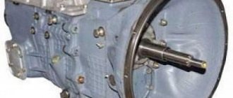
The transmission on the YaMZ 2361 is mechanical (5 steps), equipped with synchronizers in several gears. This device is produced by the Yaroslavl Motor Plant. They are equipped with heavy-duty MAZ vehicles. Depending on the configuration, YaMZ can be found on Ural vehicles and MARZ buses.
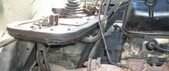
Appearance of the gearbox
The main technical characteristics of the transmission system should be considered.
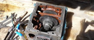
Composition of the YaMZ gearbox
A unit such as the gearbox on the YaMZ 236 is equipped with a clutch housing made of reliable materials. The amount of fuel in the gearbox housing is about 5.5 liters. The transmission system includes a heavy-duty input shaft. The secondary shaft of the gearbox on the YaMZ 236 is supported by one part on the existing bearing (roller), and the other on the ball bearing. It should be noted that the roller bearings have intermediate shaft bearings.
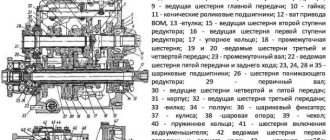
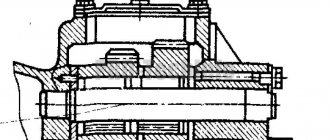
Longitudinal section of the gearbox
There is a special creeper. Thanks to it, it is possible to reduce the speed limit. The oil pump is efficient. The oil intake is covered with a mesh. This element has a magnet, which is necessary to attract metal microparticles that may be present in the oil. This system also includes a pressure reducing valve. Its main function is to maintain the outlet pressure at an optimal level during movement.
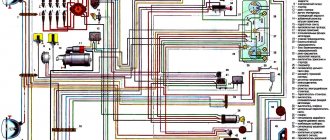
YaMZ gearbox diagram
In the top cover of the YaMZ 236 gearbox there is a mechanism that allows changing speed modes while moving. It is typical for special equipment that a gearbox (KOM) is installed, designed for a long service life. On a number of trim levels there is an electronic speedometer drive.
Transmission cover diagram
The weight of the gearbox together with the crankcase exceeds 240 kg. While the weight of the YaMZ 236 power unit reaches 1000 kg. Oil should be added to the YaMZ 236 gearbox through a special hole, which is securely closed with a plug.
The vehicle is equipped with a YaMZ-236U model gearbox.
Characteristics: mechanical, five-speed, three-shaft, with variable gearing, partially synchronized.
Installation and fastening : attached to the clutch housing, which, in turn, is attached to the frame. The rear part of the gearbox is mounted on a special support support.
Device (in accordance with Figure 101) : crankcase 64 with covers, gearbox, control drive, gear shift mechanism, lubrication system, fastening parts and seals.
Carter with covers.
Cast from gray cast iron and is the basic part of the gearbox. In the crankcase, in accordance with Figure 2.21, there are 4 bores for installing shaft bearings, in the right and left side walls there are hatches for mounting the power take-off, the upper part of the crankcase is closed with a removable cover in which the gear shift mechanism is mounted. All hatches and bores are closed with covers (through and blind).
Fig. 101. Gearbox Ural – 4320.31:
1 - input shaft; 2 — input shaft bearing cover; 3 — clutch housing; 4 - oil seal; 5 — input shaft bearing; 6 — oil drain pipe; 7 — front bearing of the secondary shaft; 8 — synchronizer of IV and V gears; 9-fork; 10 — lever handle; 11 — clamp; 12 — bushing of the third gear gear; 13 — breather; 14 — fork for shifting II and III gears; 15 — synchronizer for 2nd and 3rd gears; 16 — gear II of the driven shaft; 17 — thrust ring; 18 — fork for shifting 1st gear and reverse; 19 — 1st gear and reverse gear; 20 — rear bearing of the secondary shaft; 21 - secondary shaft; 22 — fuse spring cup; 23 — fuse spring; 24 — axis of the leash; 25 — fuse pin; 26 — protective cap; 27 — locking pin; 28 — lever spring; 29 - lever support; 30 — gearbox cover; 31 — oil filler plug; 32 — rod lock ball; 33 — rod lock pin; 34 - setscrew; 35 - leash; 36 - flange; 37 — axis of the reverse gear block; 38 - intermediate sleeve; 39 — needle bearing; 40 — reverse gear block; 41 — oil seal; 42 — cover of the rear bearing of the secondary shaft; 43 - cover of the rear bearing of the intermediate shaft; 44 - thrust washer; 45 — rear bearing of the intermediate shaft; 46 — intermediate shaft; 47 — reverse gear of the intermediate shaft; 48 — oil drain plug; 49 — gear II of the intermediate shaft; 50 — spacer sleeve; 51 - cover; 52 — magnet spring ring; 53 - magnet; 54 — oil intake; 55 — gear III gear of the intermediate shaft; 56 — gear V transmission of the intermediate shaft; 57-spline synchronizer bushing; 58 — gear III gear of the secondary shaft; 59 — oil drain plug; 60 — bushing for gear V of the secondary shaft transmission; 61 — gear V of the secondary shaft transmission; 62 — power take-off gear; 63 — intermediate shaft drive gear; 64 — gearbox housing; 65-oil pump; 66 - ring nut
The crankcase has a separate filler hole (on the top cover) and a control hole on the left side wall of the crankcase. There is a partition inside in the middle part of the crankcase.
Gearbox.
Purpose: serves to change the torque in magnitude, by increasing or decreasing the gear ratio, and direction, due to an additional gear block.
Characteristics: main, single-drive, gear, with fixed axles, gear ratios: first - 5.26; second – 2.90; third – 1.52; fourth – 1.0; fifth – 0.664; reverse gear - 5.48.
Device: ( in accordance with Figure 101) : input shaft with drive gear 1, intermediate shaft 46 assembled with gears 49,55,56,62,63, secondary shaft 21 assembled with gears 16,20,58,61 , reverse gear block 40.
The input shaft 1 is made of alloy steel along with the drive gear. At the front, it is supported by a needle bearing installed in the bore of the engine crankshaft. Its rear support, in accordance with Figure 101, is ball bearing 5.
During assembly, the front bearing is filled with lubricant, sealed with a cuff and does not require maintenance during operation. The rear bearing on the shaft is tightened with a ring nut.
The gear is helical, has an internal gear ring for connection with the gear ring of the synchronizer carriage and an axial cylindrical bore for the roller bearing of the front support of the secondary shaft. The rear part of the gear has an outer conical surface to create a friction torque between the gear and the synchronizer when direct transmission is engaged.
A bushing is inserted into the axial hole of the shaft to supply oil to the axial channel of the secondary shaft. To drain oil from the cavity of the bearing cover, an inclined drilling is performed in the input shaft. The shaft bearing cavity is sealed with an oil seal installed in the bearing cover.
The secondary shaft 21 is made of alloy steel and installed in accordance with Figure 101, on two supports coaxially with the primary shaft: the front support is a cylindrical roller bearing 7 installed in the bore of the primary shaft gear, the rear support is a ball bearing 20 installed in the bore of the rear wall gearbox housing.
The output shaft has a ground bearing journal at the front end. The rear end has slots for installing the propeller shaft flange and threads for the flange mounting nut. The nut is secured against self-loosening by a cotter pin, which is inserted into the slots, nuts and hole in the threaded part of the shaft. The shaft output is sealed with an oil seal. A synchronizer carriage for 4th and 5th gears 8 is installed on the splines of the secondary shaft. The synchronizer for 2nd and 3rd gears 15 is mounted on a splined bushing secured to the secondary shaft using a segment key.
There is an axial drilling inside the shaft, which receives lubricant from the input shaft. To supply lubricant to the gear bearings, radial drillings are made in the secondary shaft. When installing gear bushings when assembling the shaft, you must ensure that the holes in the shaft and bushings match. The first and reverse gears are engaged by moving the carriage gear along the shaft splines forward - 1st gear, back - reverse gear.
Gears 16, 19, 58, 61 are installed on the shaft in accordance with Figure 101. The gears are made of alloy steel, their working surfaces are cemented and hardened to increase the hardness of the teeth.
Gear 19 (1st gear and reverse) is installed and moves along straight splines cut on shaft 21.
Gears 61, 58, 16 (V,III,II gears) are helical, constantly meshed with the corresponding gears of the intermediate shaft, mounted on the shaft on plain bearings (bushings) and fixed in the assembly on one side by a thrust ring 17, and on the other by a special a persistent toothed washer and a figured key that locks the washer. The bushings are made of steel, cemented and hardened, and have holes for lubricant supply. The outer surfaces of the bushings have semicircular grooves that form pockets for lubrication and retention of wear particles. Gears 61, 58, 16 have additional toothed rims to ensure gear shifting, the teeth of which are made with a slight taper along their length. To ensure the creation of the required friction torque between the surface of the gear and the surface of the friction ring of the synchronizer, the gears are made integral with the cone.
The intermediate shaft 48 is made of alloy steel and installed in accordance with Figure 101, on two supports: front roller and rear ball 45 (roller in the latest modifications) bearings. The rear bearing is secured against axial movements by a retaining ring and a cover.
The shaft is forged integrally with the rims of the spur gears of first gear and reverse gear, in accordance with Figure 101, and in these gears the gears engage only when the gears are engaged. The gear wheels of the intermediate shaft drive 63, power take-off drive 62, fifth 56, third 55 and second 49 gears are helical and pressed onto the intermediate shaft, and are locked from rotation by segment keys.
The reverse gear block 37 is installed on the left side of the crankcase and has, in accordance with Figure 101, two spur gears, mounted on the axis 37 on two roller bearings 39. The axis is fixed in the crankcase with two thrust washers. The front end of the intermediate shaft is drilled with splines for connection with the shaft of the oil pump 65.
The order of transmission of torque in the gearbox.
Neutral position – synchronizers 5.10 and gear-carriage for first gear and reverse gear 12, in accordance with Figure 101, are turned off. The primary shaft 2 is rotated by the engine and rotates the intermediate shaft 17 through its gear. The intermediate shaft gears 19, 21, 22 rotate the gear wheels of the secondary shaft 8, 11. Since the gear rims of the secondary shaft wheels are disengaged from the synchronizers or gear-carriage, the torque is not transmitted to the shaft.
The first gear - the carriage gear, in accordance with Figure 102, is moved back and the ring gear is engaged with the ring gear of the first gear of the intermediate shaft.
Fig. 102.Transmission of torque in the gearbox gearbox in first gear
Torque from the primary shaft is transmitted to the intermediate shaft, and from it to the secondary shaft carriage gear and splines of the secondary shaft. The secondary shaft rotates at a frequency (speed) 5.26 times lower than the primary one, and the torque supplied to the primary shaft increases by the same amount.
Fig. 103. Transmission of torque in the gearbox gearbox in second gear
The second gear - the synchronizer carriage 10, in accordance with Figure 103, is engaged with the ring gear of the second gear 11.
Torque is transmitted from the input shaft to the intermediate shaft, from it to the gear wheel (gear) of the second gear of the secondary shaft, the synchronizer carriage and the secondary shaft. The rotational speed of the secondary shaft is 2.9 times less than the primary one, the torque on the secondary shaft is greater by the same amount.
Third and fifth gears - torque is transmitted in accordance with Figures 104, 105, similar to the second gear, with the exception of the driven gears connected to the secondary shaft.
Fig. 104. Transmission of torque in the gearbox gearbox in third gear
Fig. 105. Transmission of torque in the gearbox gearbox in fifth gear
In this case, in third gear, the secondary shaft rotates at a frequency (speed) 1.52 times less than the primary one, and the torque supplied to the primary shaft increases by the same amount; in fifth gear, the rotation speed of the secondary shaft is 0.664 times greater than the primary one, and the torque is the same amount less.
The fourth gear - synchronizer carriage 5, in accordance with Figure 106, is engaged with the ring gear of the input shaft gear.
Fig. 106. Transmission of torque in the gearbox in fourth gear
Torque from the input shaft is transmitted to the synchronizer carriage and from it to the secondary shaft. Torque is not converted, direct transmission.
Reverse gear - the carriage gear, in accordance with Figure 107, is engaged with the reverse gear block.
Fig. 107. Transmission of torque in the gearbox in reverse gear
Torque from the input shaft is transmitted through the intermediate shaft to the reverse gear block, then to the carriage gear and to the secondary shaft. The torque increases by 5.48 times, the rotation speed of the secondary shaft is less by the same amount, and the direction of rotation is reversed.
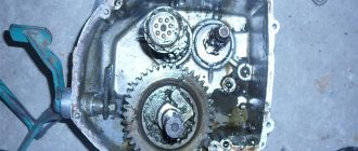
Gear shift mechanism.
Purpose: used to reliably engage the required gear.
Installation and fastening: assembled in the upper cover of the gearbox housing, synchronizers are installed on the splines of the secondary shaft.
General structure: in accordance with Figure 108, sliders 3 (3 pcs.), forks 4 (3 pcs.), clamps 2, 6 (3 pcs.), locking device (lock) 5, fuse, in accordance with Figure 101, synchronizers in accordance with Figure 101 (2 pcs.).
Fig. 108. Gear shift mechanism of the YaMZ-236U gearbox
1 – upper cover of the gearbox; 2 – clamp spring; 3 – slider; 4 – fork; 5 – locking device (lock); 6 – locking ball
Clamps serve to hold (fix) the sliders in a certain position.
Fig. 109. Latch circuit
1 – gearbox cover; 2 – spring; 3 – ball; 4 – slider; 5 – slider hole
Each of the three clamps, in accordance with Figure 109, is a spring-loaded ball 3, located in the holes 5 of the slider and holding it from moving.
When the driver acts on slider 4 when changing gears, the ball is recessed into the cover, compressing spring 2, and when another hole approaches, it drops into it, fixing the position of the slider.
The blocking (lock) device serves to prevent the simultaneous movement of two sliders and, consequently, the inclusion of two gears.
The locking device includes, in accordance with Figure 110, balls 3 (4 pcs.), pin 4.
Fig. 110. Locking device diagram:
1 - cover, 2 - sliders, 3 - balls, 4 - pin, 5 - recesses in the sliders.
The dimensions of balls 3 and pin 4, in accordance with Figure 110, are selected in such a way that the total diameter of two adjacent balls is greater than the thickness separating the partition slides in the lid.
When one of the outer sliders 2 moves, a pair of balls rolls into the recess 5 of the middle slider and stops it. At the same time, using a pin, they act on the other two balls and roll them into the recess of the other outermost slider, locking it. When the middle slider moves, the balls roll into the recesses of the outer sliders and cause them to stop (lock).
The fuse serves to prevent accidental engagement of first gear or reverse gear and includes , in accordance with Figure 111, pusher 3, rod 2, spring 1.
Fig. 111. Fuse device:
1 – spring; 2 – rod; 3 – pusher
The pusher does not allow the lower end of the tip of the gear shift lever to be inserted into the groove of the slider head. Therefore, to engage first gear or reverse gear, it is necessary to first compress the spring by moving the rod using a pusher, and only then move the corresponding slider.
Synchronizers are installed on the splines of the secondary shaft.
Purpose: used to equalize the rotation speed of connected elements when engaging gears.
Operating principle: based on equalizing the angular velocities of the included (connected) elements due to friction between the conical surfaces of the synchronizer and the gear wheel.
Characteristics: inertial, conical, cage, double-sided with locking windows, non-removable.
Device ( in accordance with Figure 112) : cage 1, coupling 5, carriage 3, cone rings 7 (2 pcs.).
The 2-3 and 4-5 gear synchronizers are similar in design and differ only in size.
Clip 4
is a hollow cylinder, in accordance with Figure 112, having shaped grooves 10.
Cone rings 7
bronze friction, riveted to the ends of the cage.
Fig. 112. Gearbox synchronizer Ural – 4320.31:
1 — carriage lock ball; 2 – clamp spring; 3 – carriage; 4 – clip; 5 – coupling; 6 – holder pin; 7 – conical rings; 8 – rivet for fastening the ring; 9 – carriage spike; 10 — figured groove of the clip
Clutch 5 is secured to four projections of carriage 3, which fit into grooves 10 of the synchronizer cage. The synchronizer is connected to the gear shift fork through the clutch.
The synchronizer carriage 3 has a spline hole that is installed on the splines of the secondary shaft (4th and 5th gear synchronizer) or on the splines of the secondary shaft spacer sleeve (2nd and 3rd gears).
To connect to the coupling, there are 4 spikes on the carriage that pass through the grooves of the cage. The neutral position of the holder and carriage is fixed using clamps, which are spring-loaded balls located in 4 drill holes in the carriage. When the gear is switched off, the balls fit into the grooves of the cage; when the gear is switched on, they are recessed into the drillings. To connect to the gear rims of the gears, external teeth are cut on both sides of the carriage.
Fig. 113. Synchronizer action:
a – neutral position; b – equalization of angular velocities of connected parts; c – engaging the gear (connection of the gear rings)
Synchronizer action . When the gear is engaged, in accordance with Figure 113 b, the fork moves the synchronizer clutch, which moves the associated carriage and synchronizer cage along the shaft. When the conical friction ring comes into contact with the cone of the gear wheel, their rotation speeds change, as a result of which the rectangular protrusions of the carriage entering the slots of the cage are shifted and enter the middle lateral recesses of the slots. Until the mutual sliding of the conical surfaces stops and the rotation speeds of the cage and gears are equalized, further movement of the carriage along the shaft axis is impossible.
After equalizing the angular velocities, in accordance with Figure 113 c, the carriage stops pressing against the middle lateral recesses of the slots and the coupling moves along with the carriage along the shaft axis, while the retainer balls are recessed into the drillings of the carriage, freeing it from connection with the holder. The ring gear of the carriage is connected to the ring gear of the gear and the transmission is engaged without shock.
Control drive.
Purpose: serves to transmit the driver’s control force to the gear shift mechanism.
Characteristic: direct.
Installation and fastening: attached to the upper cover of the gearbox housing.
Fig. 114. YaMZ-236U gearbox control drive:
1 – body; 2 – protective cap; 3 – lever; 4 – lever spring; 5 – lever support, 6 – locking pin
Device (in accordance with Figure 114) : housing 1, protective cap 2, control lever 3, lever spring 4, lever support 5, locking pin 6.
The control lever, the gear shift lever, in accordance with Figure 114, is made in one piece, without a tip. It has a ball joint 5 and is installed in a special housing 1 on a pin - retainer 6 and is pressed by a spring 4. The ball joint has a groove that allows the lever with the tip to swing in the longitudinal (along the axis of the machine) and transverse planes. The lower end of the tip moves in the grooves of the slider heads. By swinging in the transverse plane, the slider is selected, and in the longitudinal plane, the gear is engaged.
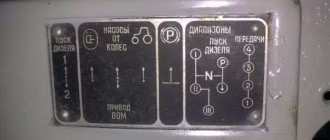
To confidently use the gear shift mechanism, the driver must clearly know the position of the lever when engaging a particular gear. To do this, a plate with a gear shift diagram is attached in a visible place on the front panel in the cab, in accordance with Figure 115.
Fig. 115. Gear shift diagram in the Ural gearbox - 4320.31
Lubrication system.
Purpose: used to lubricate under pressure the roller bearings of the secondary shaft gears.
Fig. 116. Lubrication diagram for the YaMZ-236U gearbox:
1 — input shaft channel; 2 - oil pump; 3 — crankcase channel; 4, 6 — drain plug; 5 – oil intake
Characteristics: combined.
Device (in accordance with Figure 116) : oil pump 2, oil intake 5, lines 1, 3.
Oil pump.
Purpose : used to supply oil under pressure into the system.
Characteristics: single-section, gear type.
Installation and fastening (in accordance with Figure 117) : attached to the front end of the gearbox housing and driven from the toe of the gearbox intermediate shaft.
Fig. 117. Oil pump
1 - roller; 2 - axis; 3, 11 — bushings; 4 — driven gear; 5 — pump base; 6 — valve spring; 7 - valve ball; 8 - pump housing; 9 — valve plug; 10 - drive gear
Device (in accordance with Figure 117) : base 5, housing 8, drive gear 10 with shaft 1, driven gear 4 with axis 2, pressure reducing valve 6, 7, 9.
The pump pressure reducing valve is adjusted to a pressure of 0.07 - 0.09 MPa (0.7-0.9 kgf/cm2).
The oil intake serves to clean the oil .
Installation and fastening (in accordance with Figure 116) : attached from the inside to the bottom of the box housing in the rear part.
Device (in accordance with Figure 118) : housing 1, mesh 2, magnet 3, spring 4.
Fig. 118. Oil intake
Lubrication and filling points.
The front bearing of the gearbox input shaft, located in the crankshaft bore, is lubricated when assembling the clutch and gearbox with MLi-Ka 3/13-3 grease (No. 158). During operation, replenishment of lubricant is not required.
Gearbox filling capacity 5.5 liters.
Oil used: basic at temperatures down to –30°C - TM-3-18 (TSp-15k), up to –50°C - TM-5-12RK; duplicating : up to –30°C - M-16-A (t) (MT-16p), below –30°C it is allowed to use TM-3-9 (TSp-10) oil, or TM-3-18 (k) oil with the addition of 10 -15% diesel arctic or winter fuel.
Filling is done through the filler neck (plug), level control is done using the control hole. Drain through two drain holes. After draining the used oil, clean the magnet of the front drain plug from metal particles.
Transfer case
Purpose: serves to distribute torque between the drive axles of the vehicle, increase it when driving in difficult road conditions and take power to drive additional equipment.
Characteristics: mechanical, two-stage, differential, with a permanently engaged front axle.
Installation and fastening: installed on the car frame behind the gearbox on 4 supports with rubber cushions. The transfer case is driven from the gearbox using a cardan shaft.
Device (in accordance with Figure 119): crankcase 30 with covers, gearbox, differential, gear shift and differential lock mechanism, control drive, fastening parts and seals.
Carter.
Carter 30 is cast from cast iron and is, in accordance with Figure 119, the basic part of the transfer case. The crankcase has 6 borings for the shaft bearings and hatches for mounting the transfer case. The hatches and places where the shafts exit from the transfer case, as well as the bores of the intermediate shaft bearings, are closed with covers 4, 17, 20, 23, 31, 35. For filling, draining and monitoring the lubricating oil level in the crankcase, there are filler (also known as control) and drain holes , closed with screw plugs, there is a magnet in the drain plug 8.
Gearbox.
Characteristics: gear-type, with fixed axles, four-shaft, with coaxial output shafts; gear ratios: low gear - 2.15; top gear - 1.21.
Fig. 119. Transfer case Ural – 4320.31:
1, 15, 22 - flanges; 2 - oil sump ring; 3 - nut; 4, 17 — bearing cover; 5 — rear differential bearing housing; 6- rear cage; 11 — front cage; 7 - epicyclic gear; 8 - plug; 9 — cage with the lower shaft gear; 10 — differential sun gear; 12 — differential lock clutch; 13 - bolt; 14 — front axle drive shaft; 16 - reflector; 18 — differential satellite; 19, 25 - top gears; 20, 23, 31, 35 — bearing caps; 21 - ring nut; 24, 34 — bearings; 26 — bushing; 27 - cover; 28 — gear clutch; 29, 38 — low gears; 30 - crankcase; 32 — fitting of the sealing system; 33 - input shaft; 36 — intermediate shaft; 37 — spacer sleeve; 39 — drive shaft of the intermediate and rear axles; 40 — gear shift fork rod; 41 - differential lock fork rod; 42 — clamp; 43 — differential lock fork; 44 — gear shift fork 45 — speedometer drive gear 46 — speedometer drive worm
Device (in accordance with Figure 119): input shaft assembly 33, intermediate shaft assembly 36, front axle drive shaft assembly 14, rear bogie drive shaft assembly 39.
The primary shaft assembly 33 , in accordance with Figure 119, is installed in the crankcase on two supports, which are roller tapered angular contact bearings 24 arranged barrel-shaped. The driveshaft flange 22, gear wheels of the first (low) 29 and second (high) gears 25 and the gear shift clutch of the control mechanism 28 are installed on the input shaft.
The input shaft is made of alloy steel. In the front and middle parts of the shaft, splines are cut, on which the propeller shaft flange and the gearshift clutch are installed, respectively. At the rear end of the shaft, a gear ring is cut for connection with the clutch for engaging the additional power take-off box. On the ground surfaces of the shaft, gear wheels of high (front) and low (rear) gears are mounted on bronze bushings. To supply lubricant to the gear bushings during operation of the additional power take-off box, axial and radial drillings were made in the primary shaft.
The gear wheels are helical and have an additional gear ring on the hub that connects to the gear shift clutch. To supply lubricant to the bushings in the gears, through drillings are made, through which the oil flows when the car is moving.
The shaft is secured against axial movements by bearing caps 23 and 31, and shims are installed between the front cover 23 and the crankcase. Two cuffs are installed in the front cover, sealing the shaft exit from the transfer case housing.
The intermediate shaft assembly 36 , in accordance with Figure 119, is also installed in the crankcase on two supports - tapered angular contact roller bearings 34, located barrel-shaped. The gears of the highest 19th and lowest 38th gears, a spacer bushing 37 and a speedometer drive worm 40 are installed on the shaft.
The intermediate shaft is made of alloy steel. Splines are cut on the surface of the shaft for installing gears. In places where bearings are installed on the shaft, ground journals are made. The inner races of the bearings with gears and spacer sleeve are tightened with two nuts.
Gears are helical and have internal splines for connection to the shaft. A wheel 19 of smaller diameter is installed in front (high gear), and a larger diameter 38 is installed at the rear (low gear). The long sides of the wheel hubs are directed towards each other and a spacer sleeve is installed between them on the shaft.
The speedometer drive worm 40 is installed on the front end of the intermediate shaft on a parallel key and is secured with a strip with bolts.
The installation locations of the bearings in the crankcase are closed with covers 20 and 35. Bearing shims are installed under the rear cover. The rear cover has a threaded hole into which a fitting for the tube of the unit sealing system (crankcase cavity breather) is screwed.
The front axle drive shaft assembly 14 , in accordance with Figure 119, is installed in the lower part of the crankcase. The front end of the shaft rests on an angular contact ball bearing installed in the crankcase cover 17, and the rear splined end rests on the center differential parts. The differential locking clutch 12, the differential sun gear, the oil sump ring and the front axle drive driveshaft flange 15 are installed on the shaft.
The shaft is made of alloy steel and has three splined sections. At the front end - for installing the propeller shaft flange, at the middle part - for installing the differential lock clutch, at the rear end - for the sun gear of the center differential.
The shaft exit from the crankcase cover is sealed with a self-clamping rubber seal. To reduce the load on the oil seal, an oil catch ring marked “P” is installed in front of it. When the shaft rotates, the helical grooves of the oil sump ring throw the leaked oil back into the crankcase. Axial loads on the shaft are taken by the bearing retaining ring and cover.
The rear bogie drive shaft assembly , in accordance with Figure 119, also has an angular contact ball bearing and center differential parts as supports. The driveshaft flange 1 and the ring gear (epicycle) 7 of the center differential are installed on the shaft.
The shaft is made of alloy steel and has two splined sections. The front splined end houses the differential ring gear, and the rear splined end houses the driveshaft flange. The ground journal of the shaft rests on a bearing installed in the crankcase cover. The shaft exit from the cover is sealed with a self-clamping rubber seal. To unload the oil seal, an oil sump ring 2 with the mark “3” is installed. The ring functions in the same way as on the front axle drive shaft.
The transfer case, on which the additional power take-off box is installed, has an extended input shaft and a modified crankcase in the area where the additional power take-off is attached.
The parameters of the speedometer drive gears depend on the gear ratio of the main drive of the drive axle and the size of the tires installed on the vehicle.
Transfer case differential.
Purpose: serves to ensure rotation of the drive shafts of the front axle and rear bogie at different angular speeds and distribute torque between them in a ratio of 1:2.
Characteristics: center-to-center, asymmetrical, planetary, lockable.
Installation and fastening: installed, in accordance with Figure 119, in the transfer case housing on two angular contact ball bearings. The front bearing is located in the crankcase bulkhead, the rear bearing is located in the rear differential bearing housing.
Device (according to Figure 120): front cage 2; cage with lower shaft gear 7, rear cage 8, sun gear 3, ring gear (epicyclic) gear 6, front cage support ring 4, satellites with axles - 4 pcs. 5, fastening parts.
Front race 2, race with lower shaft gear 7 and rear race
8 assembled form the differential housing, inside which its remaining elements are located.
Fig. 120. Transfer case center differential:
1 — ring gear, 2 — front race, 3 — sun gear; 4 – support ring of the front race; 5 satellites; 6 — epicyclic gear; 7 — cage with lower shaft gear, 8 — rear cage
Clip with lower shaft gear
, in accordance with Figure 119, has an elongated hub on which a ground journal is made for the bearing and a toothed rim is cut to engage with the teeth of the differential locking clutch 12. The cage disk has four holes for installing the axes of the satellites 18. The second support for the axles is, in accordance with with Figure 120, front race support ring 4, which is bolted to the race.
The lower shaft gear is helical and is in constant mesh with the low gear gear of the intermediate shaft. Thus, the housing is the leading element of the differential, to which torque is transmitted from the intermediate shaft.
Rear clip 8
made in the form of a cup with an elongated hub on which a bearing and bearing fastening nut are installed.
Front clip 2
made in the form of a ring, on the outer surface of which teeth are cut. The clips are connected to each other with bolts.
Sun gear 3
– straight-cut, has internal splines with which it is installed on the front axle drive shaft. The outer teeth are in constant mesh with the satellites.
Ring (epicyclic) gear 6
is a cup-shaped part. In the hub part of the epicycle, splines are cut for installation on the drive shaft of the rear bogie. In the widened part there is an internal spur ring, which is in constant engagement with the satellites.
Satellites 5
– spur gears made integral with the axles. The satellites are installed in the holes of the front race and support ring and are in constant engagement on one side with the sun gear, and on the other with the epicycle. The engagement of the satellites with the epicycle is internal, with the sun gear – external.
Gear shift and differential lock mechanism.
Purpose: used to change gears and lock the differential.
Device : (in accordance with Figure 119) couplings 12, 28 (2 pcs.), rods 40, 41; forks 43, 44 (2 pcs.), clamps 42 (2 pcs.).
Gear shift clutch 28 and differential lock clutch 12
similar to the clutch for shifting first gear and reverse gear of a gearbox.
Gear shift rod 40
Fork 44 is connected to gear shift clutch 28. There are three holes on the rod to fix the positions of high and low gears and neutral.
Differential lock rod 41
connected by fork 43 to differential lock clutch 12. There are two holes on the rod that allow you to fix the position of the unlocked and locked differential.
Clamps 42
They are spring-loaded balls and are similar to gearbox retainers.
Transfer case control drive.
Purpose: serves to transmit the driver’s control action to the gear shift mechanism and differential lock .
Characteristics: remote, mechanical.
Device (in accordance with Figure 121): control levers 1, 2 (2 pcs.), leads 7, 8 (2 pcs.), rods 5, 6 (2 pcs.).
Control levers 1 and 2
, in accordance with Figure 121, are installed on a bracket and brought out through the slots into the cabin. The lower ends of the control levers are connected to the leads using rods 5 and 6.
Rods 5 and 6
have threaded tips that allow you to change their length.
Leashes 7 and 8
installed on a bracket fixed to the transfer case, and using fingers connected to the rods of the gear shift mechanism 9 and differential lock 10.
Fig. 121. Transfer case control Ural - 4320.31:
Possible breakdowns
Gearbox malfunctions on YaMZ 236 can be as follows:
- the appearance of extraneous noise;
- reducing the amount of oil that is poured into the box;
- Difficulty switching gears;
- spontaneous switching off of speed modes;
- fluid leaks from the crankcase side.
In case of any of these manifestations, it is advisable to independently check the oil level in the box and how tightly all the fastening nuts and bolts are tightened. If this is not the problem, the vehicle should be sent to a service center for diagnostics. Here, technicians must use special equipment to check the integrity of the components of the gearbox (clutches, bearings, bushings, etc.) and evaluate the operating ability of the oil pump.
If necessary, mechanics at the auto center can adjust the locking clutch and the angle of the lever in the cab. In some cases, replacing faulty bearings and gears allows you to return the gearbox to an operational state. Without professional equipment, repairing a gearbox yourself will be complicated.