The gearbox cover on a UAZ loaf, like on any other car, is an important part of the gear shift control mechanism - if a malfunction occurs in it, driving the car is either impossible due to the inability to engage the gear, or is dangerous due to the fact that only some of them work from the steps.
The cover itself is the main part of the gearbox. In this regard, in case of any problems with the lever or suspicious noises from the box, it is recommended to check its condition - perhaps this part needs a complete replacement rather than minor repairs.
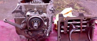
Gearbox cover UAZ loaf
The gearbox cover on a UAZ loaf, like on any other car, is an important part of the gear shift control mechanism - if a malfunction occurs in it, driving the car is either impossible due to the inability to engage the gear, or is dangerous due to the fact that only some of them work from the steps.
The cover itself is the main part of the gearbox. In this regard, in case of any problems with the lever or suspicious noises from the box, it is recommended to check its condition - perhaps this part needs a complete replacement rather than minor repairs.
Repairing the gearbox cover on a loaf
Repairing the gearbox cover on a UAZ loaf will differ depending on what problems have arisen in it.
For example, in a situation where the bushings are worn out, you can do the following: make new bushings and put the cover back, first boring out the space for it (in this case, the axles are replaced with completely new ones).
Oil dripping from axles due to worn bushings can be eliminated in another way. To do this, you will need to remove the levers, cut off pieces of small thickness from a pre-selected hose that is resistant to oils and gasoline (which is selected individually for the cover), insert them onto the axles and tighten them with the levers.
In this case, the levers will turn a little tighter, but the gear shift speed will remain the same.
Some users, if they encounter similar problems associated with wear of the splines on the axles and non-engagement of gears, advise not to repair the cover, but to purchase a new one.
In this case, the new UAZ loaf part must be upgraded before installation. To do this, fluoroplastic bushings are installed in place of the rubber bushings.
The removed bushings are cut and installed on the shafts under the levers, which ensures the absence of backlash and protects this part of the mechanism from dirt and water getting into it.
If one of the gears starts to slip out, it’s worth checking:
- the condition of the balls and springs in the gearbox cover , which fix the rods when changing gears - perhaps the cause of the problem lies in their wear, and these components require replacement;
- the condition of the gears - this can also cause gear failures;
- bushings - if the problem is in them, then this part can be strengthened.
Most often, the reason for knocking out gears lies in worn gears and balls, as well as broken springs.
In addition, before repairing the gearbox cover, you should pay attention to the general condition of the mechanism - perhaps a major breakdown, which is clearly noticeable, hides several minor problems, or the entire mechanism is so worn out that it would be wiser to replace it with a new one.
Source
UAZ car gearbox
Remove the cover with the gear shift forks. Remove the input shaft cover. Having engaged any gear, we put the copper into the teeth and unscrew the flat nut on the input shaft (it’s the left one!). Now we look inside the box - on the input shaft gear there is a cutout for a large intermediate gear. We position the shaft so that the cutout matches and press the input shaft bearing onto the shaft. The main thing is not to rush and hit in a circle so as not to distort the bearing and ruin the seat. In the photo there is a shaft that I have already taken out three times, I don’t know what happened before me. As you can see, it is hardened and does not suffer from blows. If the input shaft bearing is worn out, knock it down and install a new one. He suffers perhaps the most, so 90% of him will have to be changed. These bearings come with a closed and open cage, I don’t understand the difference - it’s still under the cover.
It lives inside the input shaft without a cage. Most likely it fell apart during disassembly. Collect it. If the last roller stands up easily, it needs to be changed. With a new set of rollers, the last one can only be inserted with great difficulty and “lengthwise”. It even seemed to me that they slipped me the wrong one :).
Remove the retaining ring from the secondary shaft and unscrew the double-row bearing stoppers. We knock out the secondary shaft. By the way, when I needed to replace only a double-row bearing, I managed to do it without disassembling anything else. I took off the retaining ring and picked it out. By the way, the box still drives.
Now we take out the 3-4 gear clutch assembly. Remember how it stood - on the contrary, it will fit onto the shaft, but the input shaft will not fit. The copper synchronizers will most likely need to be replaced, as well as three crackers with springs and balls (nowadays they sell crackers without balls, with protrusions, which are easier to assemble). When assembling the coupling, do not turn the inner part relative to the outer one. We take out the secondary shaft and repair the shaft, double row and gears.
Remove the reverse gear shaft. To do this, use a flat-head screwdriver to unscrew the locking screw from the hole (marked in red in the figure), and then knock the shaft out of the box. Inside the gear there is a multi-row bearing with a plastic cage; we take out the retaining rings, the metal tube and remove the defective bearing. The box from the 72nd edition turned out to be intact :).
Unscrew the cover of the front bearing of the intermediate shaft. Try to keep the rubber seal on the lid - it’s a problem to buy. I do not recommend unscrewing it with a core - the lid is made of silumin. I unscrewed it with duckbills with curved ends, but you can make a key like a grinder from a piece of metal and two bolts. The photo shows how the holes become deformed after a couple of unscrewings. We put a piece of copper in the teeth of the gear and unscrew the bolt and nut of the shaft. Left bolt! The nut is 36, I specifically mentioned the key for it. Now you can knock out the shaft and replace (if necessary) the gears and bearings. Well, that's all, now we assemble the box with new parts in the reverse order. The outer bearing races should not rotate in their seats. You can combat this by piercing the entire surface of the seat with a herringbone pattern every 5-7 mm (c). If this does not help, the case needs to be replaced. When installing the rollers in the input shaft, generously coat them with “Litol” or something similar and put them on very carefully (the process is fun, like threading a needle). When installing the input shaft bearing cap, pay attention to the cutout in the gasket for the oil channel - it will probably have to be modified. Before installing the gear shift cover, compare the result with the photo. It wasn't all right for me the first time :). When installing a cover with forks, make sure that the forks are in the right place.
Transfer case
First you need to loosen the nuts of the flanges and transfer case shafts - to do this, insert bolts of suitable diameter into the two holes of the flange and hold them in place. The shaft nuts are hidden under the covers; they must be unscrewed - the shafts can be removed with the nuts, but then it is very difficult to unscrew them. By unscrewing the flanges, remove the handbrake (at the same time you can check its functionality and change the pads). The soured working cylinder is disassembled and soaked in diesel fuel, checked. There are no spare parts for the brake - either pads or everything assembled.
We remove the covers with seals and change the seals (unless they are completely new), not forgetting to fill the free space with “Litol.” Unscrew the bolt by 10 and remove the speedometer drive. We unscrew the breather and replace it with a new one (100% soured). Better yet, call the phone to the salon. Unscrew the stopper of the guide forks.
Now you can “halve” the transfer case - Remove all the retaining rings from the bearings, unscrew all the bolts around the perimeter and remove the large cover. If necessary, we change the roller bearing in this cover, the inner race is pressed onto the shaft. There are two bearings on the rear axle shaft, the second one must be inspected.
The transfer case is assembled in reverse order. You need to carefully inspect the flanges and replace them at the slightest sign of wear on the splines; it progresses very quickly. Wear on the forks is also unacceptable. Don't forget to core the nuts.
Let me add one detail to your story about the repair of the RC, namely: when you change the roller bearing on the intermediate shaft, you need to knock out the plug in the RC housing that closes it, because The bearing race is pressed in 3 mm from the outer edge of the housing (you won’t be able to catch this without removing the plug). The plug itself is placed in its place on the fully assembled bearing (so that you can check the bearing tension). Before installation, straighten the plug on the plate, then a thin layer of sealant is applied to the edges of the hole in the RC body under the plug and the plug is seated in place using a mandrel (instead, you can use a piece of pipe with a diameter 6-8 mm smaller, i.e. a tight fit is achieved due to uniform indentation of the middle).
Question about the box and the loaf
Recommend where to watch:
The situation is as follows: The loaf was rolling normally until the clutch began to bleed. It was poisoning and at some point after engaging 4th gear, the reverse gear did not go out, so it got stuck in 4th speed. They crawled under the car, knocked out the transmission and pulled the lever on the box back. Speeds include 1,2,3. 4 turns on, but in 70% of cases it doesn’t come back out on its own, it also bites. However, when any gear is engaged (1,2,3,4), there is no feed to the cardan, although there is a click when engaged. The clutch was checked - the discs move away, press back, etc. . but there is no supply.
Question: What's in the box?
Re: Question about the box and the loaf IMHO due to problems with the clutch, the gear shift lever was probably twitching somewhat nervously, as a result of which the forks for moving the gears along the shafts were bent, or parts of the shift mechanism were damaged. IMHO You need to remove the cover from the box and look at the condition of the forks and the shift mechanism. Well, as for the clutch, you have to deal with it separately (to be honest, I didn’t understand what “the clutch is leaking”) means.
Best regards, aas
Re: Question about the box and the loaf The clutch releases: What I wanted to say is that when you squeeze and try to keep the pedal “to the floor”, after 5-10 seconds the clutch begins to “drive”, i.e. the rod goes back. The problem was solved by replacing the upper cylinder, because... On the old one the cuff was leaking.
Is it possible to remove the box cover without removing the box?
PS I apologize for the possibly stupid questions, but I ride a Gazelle, and then the company bought a UAZ, they asked me to “bring it to mind.” Here we have to figure it out. The engines seem to be the same, but there is a problem with the gearboxes and transfer cases.
Re: Question about the box and the loaf. I think the lid can be removed without removing the box. I didn’t take it off myself, but it doesn’t seem to interfere with anything. The only thing is that there is such a feature: the gearbox and transfer case have, in fact, a common oil bath, that is, oil can flow from the box to the transfer case and back.
Source
Before repairing the gearbox
Look at what kind of gearbox you have. If you're not familiar with the concept of double-throttle, all gears, both up and down, shift easily, and the lever travels the same distance when engaging first gear as when engaging third - you have a fully synchronized gearbox. Everything that will be written further about the gearbox does not apply to you. However, the transfer cases are the same, and you may still find some of this article useful. For off-road use, a gearbox with synchronizers only in third or fourth gears is preferable, the so-called. "old style".
Having decided on the type of your box, we will prepare the tool. To completely disassemble and reassemble the “old-style” gearbox and transfer case without any special tricks, you need the following tool:
- Open-end wrenches - 10, 12, 13, 14, 17, 19, 22. It would be better in two copies. Particular attention should be paid to the 14th key - it should not be very thick and under no circumstances bend, otherwise turning the rear driveshaft away from the transfer case flange can cause trouble.
- Socket wrenches - 10, 12, 13, 14, 17, 19, 22, 24, 27, 36. The thinner the walls, the better. The usual domestic set of heads did not fit everywhere. 36 heads are not found in all sets; I bought a hub key from a GAZelle and passed it with flying colors. And it was cheap.
- A special wrench for tightening flat nuts - these are found on the steering column of bicycles. I also picked up a bicycle key, but in general this is wrong.
- Screwdrivers - flat and Phillips. Both powerful for large screws and small ones.
- Platypuses - regular straight ones with curved noses for removing and putting on locking rings.
- Something copper to stick between the gear teeth when loosening and tightening the shaft nuts. I used an old synchronizer.
- A drift is a metal pin, preferably made of copper.
- A piece of metal pipe - for putting on keys. Sometimes the nuts and bolts are so tight that they cannot be unscrewed otherwise.
- Core and chisel. The core must be of high quality so that upon impact, its pieces do not fly into the brand new bearing.
- Mounting blade. This is how the wheels are usually mounted. A very necessary thing.
- Hammer. It should be quite heavy, sometimes you have to hit it “as hard as you can.”
- Cans for screws and other small items. The more, the better - when you put everything back together, you will appreciate this advice.
- Bearing puller. You can do without it, but it’s a convenient thing.
- A book and catalog with good pictures. Necessarily. And read before you start unscrewing anything. Pay special attention to places where there are left-handed threads and the location of washers, stops and other small items. It’s best to remember (or write down) everything when disassembling
I use red ABRO sealant for gaskets. Domestic white is only suitable for water supply, and even then not everywhere.
I use Litol as the cheapest grease. Gaskets are sold in sets “For gearbox” and “For transfer case”. All gaskets need to be changed; leaving the old ones will not work. It is also useful (but not necessary) to buy a “Gearbox Repair Kit” and a “Transfer Box Repair Kit”, which consist of retaining rings, shims and other small things that would be better to change. I really couldn’t find a distribution kit in all of St. Petersburg, but there are almost no small things there.
Removing the Gearbox-Transfer Box Assembly
In UAZ vehicles, the gearbox and transfer case are interlocked into one unit, which is very correct. But it’s very heavy (80 kg). Therefore, it is quite difficult to remove this weighty unit alone (and this is exactly what happens most often). The photo shows how I get out of the situation - using the Lika-2 manual winch. But I have a roll cage that I hook her to. Having once forgotten the winch, I got out of the situation with the help of an ordinary crowbar and rope. But I won’t undertake to put the box in place without a winch alone.
So let's begin. We place the car on a flat surface, taking into account that it will have to be rolled half a meter back and forth. We drain the oil - the gearbox and transfer case have separate drain and filler plugs, although the volume is the same.
While the oil is draining, remove the front seats. Then we unscrew and remove the two halves of the hatch in the floor. We unscrew and remove the speedometer drive away.
The oil is just glass, we wrap it in place of the plug. We unscrew the frame cross member that runs directly under the handbrake drum. We unscrew the cardans from the transfer case flanges. It is more convenient to unscrew the front driveshaft if the front axle clutches are disconnected. If your cardans have weak spline joint nuts, it’s better to remove the cardans completely, but in general it’s enough to tie them to the frame so they don’t get in the way. It is much more convenient to unscrew the rear driveshaft from above, from the hatch; this is where the car will have to be slightly rolled forward and backward. We unscrew the muffler from the transfer case and loosen the clamp on the muffler itself, otherwise it will interfere.
Unscrew the clutch pan. We unscrew the fastening of the oiler of the input shaft splines (on the right side of the bell) and push the hose inside the bell. We unscrew the four bolts securing the clutch fork housing, remove the spring, twist the adjustment on the working cylinder rod and pull out the fork.
We wrap a rope around the box with the transfer case and hang it up. We unscrew and remove the bolts of the pillows, unscrew the nuts securing the box to the bell. Do this gradually; the nuts on the left side will only be completely unscrewed when the box has already partially moved away from the bell. Help yourself with editing. In this case, it is better to support the engine with a jack, otherwise it will remain on two supports and the “rear” part will lower and interfere. When the box finally hangs, carefully lower it down. It is better to change the studs in the bell - they are under heavy loads, and it is 50/50 that the threads on them are damaged. If the car is standing on the ground, to make it easier to pull it out from under the car, the levers must be removed. When removing the gear shift lever, you need to hold the cover - there is a spring under it.
Remove the handbrake lever so it doesn't interfere. By unscrewing two bolts and two nuts, we disconnect the gearbox and transfer case. Since the gasket between them is probably sealed, they are separated by several blows to the bracket securing the unit to the frame. Don't lose the "Countershaft Thrust Washer". If it is there and differs from the photograph, I beg you to take a photograph and send the photo to me, I have never seen it. The photo shows an oil squeegee ring out of the box, the correct diameter.
how to install the cover with forks?
how to install the cover with forks?
slava_uaz_kiev » Fri Versnya 13, 2013 9:47
Good afternoon UAZ 469B. Gearbox - 4 mortar of the old style (synchronized 3/4 gear). Oil was constantly pouring from the gearbox (from the place of the cover with the gear selector lever) I decided to fix the problem, since adding 1 liter of oil after each train was not glamorous. I removed the cover with the lever, looked for no cracks and no gasket. I cut out the gasket and, like, well done, put it back. I wiped everything dry, where the lid fits to the box, washed it with gasoline... in general, everything is beautiful and good. But . when removing, I accidentally grabbed the lever itself and it flew off neutral.. that is, 1 - gearbox in neutral (the secondary shaft spins, the one that goes to the transfer case and rear driveshaft) and in the book it was written that you need to put it in neutral and only then remove 2 - forks didn’t move and are also in the neutral position (I hope I didn’t move them along the axis) 3 - and the rod itself that moves these forks - the lever - moved somewhere and now .. in general, scold me .. that I did something wrong and how to choose neutral in a car... but it turns out - I put everything back - but the lever is dead in position and doesn’t switch anywhere at all. In general, I accidentally misplaced the position of the lever. 1. how to check, just in case, whether the forks are positioned correctly in neutral 2 - how to set the lever to neutral? Thank you.
Just in case, how can I check if the forks are in neutral? — to be sure that they are in neutral. I’m just sitting and turning over different options in my head... what if
Re: how to install a cover with forks?
Airi » Friday Wednesday 13, 2013 10:50
Every person is an egoist, so he loves most what he has invested himself in most. Always smile. You will extend your life, please your friends, and annoy your enemies.
Re: how to install a cover with forks?
slava_uaz_kiev » Friday 13, 2013 11:37
Re: how to install a cover with forks?
slava_uaz_kiev » Friday 13, 2013 11:40
Re: how to install a cover with forks?
Airi » Friday Wednesday 13, 2013 11:54
Every person is an egoist, so he loves most what he has invested himself in most. Always smile. You will extend your life, please your friends, and annoy your enemies.
Re: how to install a cover with forks?
slava_uaz_kiev » Friday 13, 2013 12:02
along the way, for the future so that you don’t knock on the forum at night - if the forks are not in neutral, is it difficult to put them in neutral? the forks themselves without a stem
the box is in neutral for sure - since the secondary shaft (where the rear cardan is “soldered”) is spinning) now all that remains is to get in with the forks and the rod)
UAZ 3303 GОL0VⓐSTジ › Logbook › Replacing the shaft and gear shift lever
Hello everyone... in general, I solved my small problem. Now I’ll explain how I decided not to lose the balls that will fly out when the rods are knocked out.
If you remove or disassemble the cover, place each fork on its own stem when removing it.
To begin with, I replaced the o-ring under which my transmission was leaking.
Here is approximately the new and old lever, the new one comes with an additional washer.
The rollers... the new shaft turned out to be hardened, and the thread was no longer 8, but 10. It fit into the old coupling as if it were original, there was a slight play left, but not much at all.
The shaft is assembled with a thrust washer, a coupling and some other washer. In such an assembly it should be located in the gearbox cover.
But it’s in its proper place... I installed it without any problems. There’s a spring on top, a lid and that’s it...
Start of the process. To remove the shaft, I needed to knock out two rods that hold the forks.
The first small problem with this ball can be solved by pressing on the side and gently tapping the rod. Don't forget to lose it.
I installed the second fork... In fact, I removed the forks twice, at first I think I’ll do some hard work and install the forks... I installed it, which means I need to move on. And then, paying attention to the shaft, I understand that I’ll install it with three horseradish forks. I had to remove them again and install the shaft with the coupling.
This is exactly my first part of the assembly.
All the plugs are in place, the main thing is not to confuse which side goes where and which side goes where,
This ball can be thrown into place at the very last moment, otherwise it will interfere with the installation of the third fork.
Collected everything, business
with my slowness, and two assemblies, for a couple of hours
.
Repairing the UAZ 452 Gearbox Cover with Your Own Hands
If you are the owner of a UAZ and there are suspicions that the transmission has failed, then you should definitely undertake repairs. The unit fails when the driver has to hold the gearshift lever while driving, when they begin to shift on their own (to prevent this, drivers tie them with ropes). Squeaks are heard from time to time.
To get acquainted with the repair technology, read about repairing the UAZ 452 gearbox yourself. First you need to find the type of UAZ gearbox that is on the car. Despite the differences between car models, they are equipped with similar transfer cases. Therefore, we can assume that the repairs are carried out virtually identically. To do this, you will need a set of keys, some tools and auxiliary aids (their list is given below).
On most car models of this type, both parts are one piece. The weight of such a unit reaches 75-82 kg, so you will need an assistant. If the vehicle being repaired has a safety cage, then you can use a hand winch to remove the UAZ 452 gearbox for repair.
The machine needs to be placed on a level place, because then it will have to be moved 0.5 m forward or backward. First drain the oil. Both boxes have the same volume, but the plugs for draining the water are separate. While the oil is pouring out, you need to remove the front seats and unscrew them, and then put the hatch halves on the floor of the car. Next comes the turn of removing the speedometer rods.
When the oil has drained, screw the drain plugs into place. There is a frame cross member under the handbrake drum that needs to be removed. Disconnect the front axle clutches and unscrew the front universal joint. If you find that the nuts on it are weak, then you need to remove this part.
Loaf. By purchasing and delivering? Krishka checkpoint
If a UAZ 3303 gearbox is being repaired, you need to be careful with the clutches. The car is moved 0.5 m (in either direction) and the rear cardan is removed through the hatch. Disconnect the muffler from the transfer box and loosen the clamp on it. Then the following parts are removed alternately:
- clutch pan;
- fastening the oiler from the input shaft (it is located on the right, on the bell);
- 4 bolts that hold the clutch fork housing;
- adjusting the cylinder rod and fork.
The transfer case is wrapped with a rope and suspended. Remove the following parts:
- pillow bolts;
- nuts holding the bell box fastening.
During these actions, when repairing the UAZ 452 gearbox on your own, the engine must be supported with a jack. When the box is free, it is lowered and removed from under the car. The levers must be removed in advance. The bell pins need to be replaced with new ones.
If it is necessary to repair the UAZ Patriot gearbox, then you need to take into account that the placement of the box and bell is reversed. This also applies to the location of the rods. But in general, the development of a UAZ 452 gearbox for repair on its own is suitable for use.
Unscrew the bolts and nuts, disconnect the box and its transfer case. There is a gasket between them, reinforced with sealant, so you will have to hit the bracket securing the unit to the frame a couple of times.
First you need to remove the input shaft cover and unscrew the left nut that is on it (see figure). Now you need to remove its bearing. If it fails, it needs to be replaced. Its roller “brother” is installed inside the shaft, it also needs to be changed. Then the retaining ring is removed from the secondary roll. Unscrew the double row bearing stopper. The shaft needs to be knocked out and the part replaced.
Next comes the third gear clutch assembly. Copper synchronizers are replaced together with crackers. Then comes the turn of the reverse gear. Unscrew the front bearing box of the intermediate shaft. Do not hit it with a hammer or core: it is made of silumin and may crack.
Try not to destroy its rubber gasket, as it is difficult to remove. On the removed shaft, the gears and all bearings are replaced. Then the box is assembled in reverse order. When installing the roller on the input shaft, it is generously lubricated with Litol. All components and parts are put in place alternately, so as not to make a mistake.
Loosen the nuts of the flanges and shafts and remove them. The handbrake needs to be checked for functionality; if it becomes useful, it needs to be replaced. Remove all covers and replace seals. Unscrew the speedometer linkage drive and the breather (it needs to be replaced). Bearings are inspected and replaced as necessary.
Installation of the gearbox together with the RK on the UAZ 452 without assistants
This is a machine translation of a Ukrainian article. You can read the original here.
Installing a gearbox (gearbox) together with a transfer case (RK) on a UAZ 452 car is not the easiest thing, since the weight of the two assembled units is about 80 kg. In principle, this problem can be solved simply, if there are 1 or 2 assistants, I want to tell you how to install the gearbox along with the LCD yourself without assistants.
Let's go from the very beginning - “why remove the gearbox on a UAZ 452? ". There are many answers, here are the most typical:
- To remove the clutch basket and disc, the release bearing must be removed from the gearbox.
- To remove the engine you need to disconnect the gearbox.
- To sort through the gearbox and gearbox, you need to remove the gearbox.
In terms of the question “How to remove the gearbox on a UAZ 452,” I think no one has any questions - this is a trivial task, to remove it you need to unscrew everything that gets in the way, but “how to install the gearbox on a UAZ 452 yourself” is far from a simple task and has many options . One of these options will be discussed further.
How to install a gearbox assembled with a switchgear on a UAZ 452 independently, without assistants?
In the body of the car we make two technical holes with an 8mm drill (see Fig. 1) into which we insert a steel wire 1.5 m long.
Rice . 1
We hook the edges of the wire to the holes in the gearbox near the gearbox mounting ears (see Fig. 2).
Rice . 2
We start the hydraulic jack (5t) as shown in Fig. 3 and begin to raise the gearbox.
Rice . 3
Having raised the gearbox for the first time to the full length of the jack, we look at the gearbox shaft; it should already be close to the clutch housing; if not, you need to place a wooden scaffold under the gearbox and lower the jack. Then place a scaffold under the jack and continue lifting. When the input shaft is lower, but along with the clutch housing, you need to move the gearbox back, and then point the shaft into the clutch basket.
We directed, we lift further, but carefully so as not to damage the clutch disc and clutch release mechanisms. You need to lift until the studs securing the gearbox to the clutch housing do NOT coincide with the holes on the gearbox. Of course, all 4 holes are unlikely to coincide; this is a matter of skill and depends on many factors. It is necessary to lay pry bars, crowbars, raise or lower the engine in order to align the imaginary axis of the gearbox and engine. There is no need to try too hard, if the gearbox shaft rests on something, then it rests either on the clutch ferrode, or on the bearing on the flywheel, or on the flywheel, so you need to be careful. First, we take the flywheel with both hands and try to turn it; to make this easier, you can unscrew the spark plugs on the engine. If turning the flywheel and directing the gearbox to the studs does not give the desired result, you need to partially release the clutch basket. To do this, loosen all 6 bolts securing the clutch basket to the flywheel a few turns and turn the flywheel by hand, try to direct the gearbox, if not a single pin wants to fit into the hole, you will have to completely unscrew the clutch basket from the flywheel and partially move it back. We take a flashlight and shine it into the gap between the flywheel and the feredo, put a thin pry bar into the gap and direct the end of the input shaft into the bearing on the flywheel, and the feredo onto the teeth of the gearbox input shaft. Now we screw on the clutch basket and, using force and a pry bar, place the holes on the gearbox on the gearbox mounting studs, which are located on the clutch housing. To prevent the gearbox from falling back, we tighten the nuts.
Pay attention ! On the right side of the car, nuts with long threads are used, on the left with short threads. The left side is difficult to tighten, since the nut rests against the gearbox housing and needs to be pressed out. First you need to bait the left side, and then press the right.
Then we just attach the gearbox mounting ears to the frame, cut off the wire, connect the transfer case rods, syringe the release bearing, connect the universal joints, connect the clutch, connect the gearbox rods.
Photos on the topic:
Photo of UAZ 452 checkpoint
Photo of clutch housing UAZ 452
www.ukr-autoblog.net
Repairing the gearbox cover on a loaf
Repairing the gearbox cover on a UAZ loaf will differ depending on what problems have arisen in it.
For example, in a situation where the bushings are worn out, you can do the following: make new bushings and put the cover back, first boring out the space for it (in this case, the axles are replaced with completely new ones).
Oil dripping from axles due to worn bushings can be eliminated in another way. To do this, you will need to remove the levers, cut off pieces of small thickness from a pre-selected hose that is resistant to oils and gasoline (which is selected individually for the cover), insert them onto the axles and tighten them with the levers.
In this case, the levers will turn a little tighter, but the gear shift speed will remain the same.
Some users, if they encounter similar problems associated with wear of the splines on the axles and non-engagement of gears, advise not to repair the cover, but to purchase a new one.
In this case, the new UAZ loaf part must be upgraded before installation. To do this, fluoroplastic bushings are installed in place of the rubber bushings.
The removed bushings are cut and installed on the shafts under the levers, which ensures the absence of backlash and protects this part of the mechanism from dirt and water getting into it.
If one of the gears starts to slip out, it’s worth checking:
- the condition of the balls and springs in the gearbox cover , which fix the rods when changing gears - perhaps the cause of the problem lies in their wear, and these components require replacement;
- the condition of the gears - this can also cause gear failures;
- bushings - if the problem is in them, then this part can be strengthened.
Most often, the reason for knocking out gears lies in worn gears and balls, as well as broken springs.
In addition, before repairing the gearbox cover, you should pay attention to the general condition of the mechanism - perhaps a major breakdown, which is clearly noticeable, hides several minor problems, or the entire mechanism is so worn out that it would be wiser to replace it with a new one.
AutoNews / Reviews / Tests
Repairing the UAZ 452 Gearbox Do-It-Yourself Video
If you are the owner of a UAZ and there are suspicions that the transmission has failed, then you should definitely undertake repairs. The unit fails when the driver has to hold the gearshift lever while driving when they begin to shift on their own (to prevent this, drivers tie them with ropes). Creaks are heard.
Assembling a synchronized gearbox
Assemble the gearbox, starting with the subassembly of its components, in the following order:
Assembling the input shaft
Latch the blocking ring onto the shaft cone to a size of 0.8–1.25 mm, as shown in Fig. 36
Press the ball bearing all the way with the sealing ring towards the bearing nut.
Screw on the bearing mounting nut (left-hand thread) and lock it by centering it in the groove of the shaft.
Place grease in the shaft hole and insert the rollers (14 pieces).
Synchronizer assembly
Select a set of couplings and synchronizer hubs with minimal clearances during free movement according to Fig. 37 or use factory-selected kits 469–1701117 and 469–1701138.
Place three springs (Fig. 38), three guide springs, three balls and three crackers in the hub and install the clutch on the hub (the clutch for 1st and 2nd gears is made integral with the reverse gear).
Install the crackers with the side with the smaller diameter holes towards the coupling.
Secondary shaft assembly
Install the 3rd gear needle bearing, bearing spacer, snap ring and key.
Latch the synchronizer blocking ring on the third gear cone to a size of 0.8–1.25 mm, as shown in Fig. 39.
Lubricate the bearing with transmission oil, install the 3rd gear gear with a locking ring, a thrust ring, install the 3rd and 4th gear synchronizer and the locking ring with the cut to the hub key.
Latch the synchronizer blocking rings on the cones of the 1st and 2nd gears to a size of 0.8–1.25 mm, as shown in Fig. 39.
Install the 2nd gear needle bearing and retaining ring.
Lubricate the bearing with transmission oil, install the 2nd gear with a blocking ring, a thrust ring, and install the 1st and 2nd gear synchronizer.
Install the thrust ring, retaining ring, 1st gear gear with blocking ring and lubricated bearing, install the spacer ring (oil slinger) so that the pin of the secondary shaft fits into the groove of the spacer ring (oil slinger).
Install the lock bushing and secure it (the lock bushing will make it easier to install the output shaft assembly into the transmission housing).
Blog about UAZ
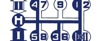
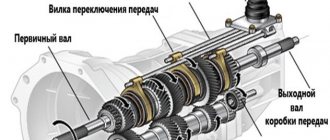
The gear shift mechanism of the four-speed semi-synchronized gearbox of the UAZ-452 family is mounted in the side cover of the gearbox. The gearshift forks are attached to the rods using a conical screw pinned with wire.
The movement of the forks when shifting gears occurs together with the rods, which have a socket for a locking screw and grooves for clamps and a locking device. The middle rod also has an intermediate pin of the locking device. When one of the gears is engaged, the rod moves and locks the adjacent rods with a rod through the cracks.
Thus, each of the remaining rods is locked with a key lock and cannot be moved out of the neutral position until the previously switched rod is returned to the neutral position. The same lock prevents two gears from being engaged at the same time.
The forks in the neutral position and in the positions with the gears engaged are fixed with balls. To switch the forks, a clutch with a lever is used, mounted on the splines of the vertical shaft. The head of the clutch lever fits into the grooves of the forks. The coupling can move along the roller in the axial direction. When the shaft rotates, the clutch rotates and its lever moves one or another fork.
In this case, in the uppermost position, the clutch is connected to the first and second gear forks, in the middle position - to the third and fourth gear forks, and in the lowest position - to the reverse fork. The middle position of the coupling is fixed by the coupling resting on the washer against which the spring rests. In order for the clutch to reach its lowest position, additional force must be applied to compress the spring. The outer end of the shaft is splined and threaded to accommodate the gear shift lever.
To move the coupling up and down, there is a control lever that rotates on the shaft and fits into the groove of the coupling. The outer end of the roller has splines and threads for attaching the outer lever. The rollers are sealed with round rubber rings.
The outer control and shift levers have a slotted hole at one end, and holes at the other end into which rubber pads with brass bushings are inserted. When installing control and shift levers on the splines, deviation from the positions is allowed within 5 degrees in any direction.
Positions of the outer gear shift levers.
Control mechanism of a four-speed gearbox UAZ-452.
This mechanism consists of two levers - control and switching, rotating in mutually perpendicular planes. Both levers are installed in a bracket that is attached to the cab. At the end of the long arm of the control lever there is a hole for connecting the rod; at the end of the short arm there is a fork into which the lever fits. In the middle position, the lever is fixed with a locking ball.
The shift lever is connected at one end to the rod, and at the other to the main gear shift lever using a forked protrusion with holes. The main lever is mounted on an axis that is screwed into the body of the shift lever. The axle is locked with a locknut. The main shift lever hinge is protected from dust by a polyethylene seal that covers the hole in the cabin air duct. The edges of the hole are sealed with foam rubber, pressed with a steel clip.
The main lever first rotates laterally relative to the shift lever and then rotates only with the shift lever to engage the desired gear. The vertical rod is attached to the control lever using a pin, cotter pin, flat and spring washers. The shift lever is connected to the vertical rod with a pin and a cotter pin.
The lower ends of both rods have threads that allow you to change their length. To adjust the length of the rods, pins are placed on their threaded ends, secured with two nuts. By unscrewing or screwing the nuts, you can change the length of the rods without disassembling the connection.
The cylindrical parts of the pins with square heads are connected to the intermediate arms using cotter pins, flat washers and spring washers. The intermediate lever assembly is mounted on the second cross member of the vehicle frame. All intermediate levers are mounted on one axis: the upper intermediate control lever is knurled, the lower intermediate control lever is secured with a radial pin, the intermediate shift lever is freely mounted on a bronze bushing. The axle has holes for lubricant supply.
The intermediate levers are connected to the gearbox levers by horizontal rods, the opposite ends of which are connected to the gearbox levers using pins with square heads.
Operation of control and gear shift mechanisms of the UAZ-452 gearbox.
The lever in the cabin can move in two planes - parallel to the axis of the car and perpendicular to it. When this lever moves perpendicular to the axis of the car, its lower end moves the control lever and, through a system of rods and intermediate levers, inserts the shift clutch into the desired position.
When the horizontal rod moves backward, the shift clutch is connected to the first and second gear forks, and when moving forward, it is connected to the reverse fork.
When the lever moves in the cabin in a direction parallel to the axis of the car, the gear selected by the previous movement is switched. The control lever of the control mechanism remains stationary, and only the shift lever rotates.
Adjustment of control mechanisms and gear shifting of the UAZ-452 gearbox.
The control mechanism and gear shift mechanism after adjustment should ensure proper operation of the gearbox and comfortable operation for the driver. The adjustment procedure is as follows:
— Set the levers on the gearbox cover to the neutral position. — By changing the length of the horizontal rods, install the intermediate levers so that their lower arms are directed vertically downward. — By changing the length of the vertical control rod, install the mechanism control lever on the clamp. — Then select the length of the vertical shift rod so that the lever handle in the cockpit is in the middle position between the instrument panel and the hood. — Securely fasten the rod nuts.
Assembling an old-style UAZ 469 gearbox
The four-speed semi-synchronized gearbox of the UAZ-469 and UAZ-452 families is mechanical, designed to change the torque transmitted to the drive wheels in order to obtain the best traction and dynamic qualities in these road conditions.
To do this, the gearbox has four gears for forward movement and one for reverse movement. The gearbox is equipped with inertia-type synchronizers to facilitate engagement of third and fourth gear.
Technical characteristics of the UAZ four-speed semi-synchronized gearbox.
— Center-to-center distance in mm: 80.5 — Maximum torque on the input shaft in kgcm: 17 — Number of pairs of constant-mesh gears: 3 — Helical gear module: 3 — Spur gear module: 3.5 — Box input shaft splines: number of splines — 10 outer diameter in mm — 35-0.075, 35-0.160 inner diameter in mm — 26.5-0.52 slot width in mm — 5.385-0.05 — Gearbox weight in kg: 34 — Crankcase filling capacity in l: 1.0
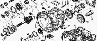
Four-speed semi-synchronized gearbox UAZ-469 and UAZ-452, device.
The gearbox is attached to the clutch housing with four studs screwed into the clutch housing. The drive gears of the intermediate shaft of the second and third gears are helical and are in constant engagement. The primary shaft has two bearings. The front bearing is located in the crankshaft housing, the rear bearing is located in the front wall of the gearbox housing.
The rear bearing is secured to the shaft with a special nut with a left-hand thread. On the inside of the crankcase, the bearing is covered with an oil deflector. There are two ring gears cut on the back of the shaft. For ease of installation, the spur ring and part of the conical surface of the shaft have an arcuate cutout.
The secondary shaft is located behind the primary on the same axis and has two supports. The front shaft support is a set of rollers placed in the input shaft. The rear shaft support is a double-row angular contact ball bearing. There is an oil deflector between the bearing and the end of the shaft.
The intermediate shaft is mounted on two ball bearings, in the front and rear walls of the crankcase. The front bearing is secured to the shaft with a special nut, which is locked by pressing its collar into the groove of the shaft. The rear bearing has a thrust ring on the outer race. The rear bearing is secured to the shaft using a Belleville washer and a special bolt with a left-hand thread.
The reverse gear block is installed with a bearing assembly on an axle, which is locked in the crankcase with a special threaded pin from the side of the crankcase hatch. The four-speed semi-synchronized gearbox of the UAZ-469 and UAZ-452 family vehicles has the following gear ratios: 1st gear - 4.124, 2nd gear - 2.641, 3rd gear - 1.58, 4th gear - 1.00, reverse gear - 5.224.
Gearbox synchronizers.
Inertial type, the synchronizer mechanism is assembled on the hub. The hub has three longitudinal rectangular grooves for placing crackers. A hole is made in the radial direction in the center of each groove.
When assembling the mechanism, springs are installed in the holes of the hub, and steel balls are installed in the holes of the crackers. To prevent the balls from falling out, the holes in the crackers are made in steps. In the synchronizer, the cotters are installed with the side with the smaller diameter holes facing the clutch.
Assembling and selection of synchronizer parts.
Gear shift mechanism.
It has three shift forks that are connected to the moving elements of the gearbox. All forks are attached to the rods using bolts that have a cone at the end. The rods together with the forks move in the axial direction. To fix the neutral position and the engaged gear, the rods have spring clamps. A locking device is installed between the rods, which prevents the simultaneous engagement of two gears. One of the rods, removed from the neutral, locks the others.
Gear shift mechanism of the gearbox on vehicles of the UAZ-469 family.
All shift forks have tabs with grooves into which the gear shift lever fits. Moving the lever in a direction across the axis of the car selects the fork, and moving the lever along the axis of the car engages the selected gear. Between the grooves of the forks of the first - second and third - direct gears, the lever moves freely.
To insert the lever into the groove of the reverse fork, you need to overcome the resistance of the fuse. The fuse is a mushroom-shaped plunger equipped with a position lock, a return spring and a locking ring that limits the stroke of the plunger. The fuse is closed from the outside with a cover.
Repair of UAZ Bukhanka gearbox (removal, repair, installation)
Rice.
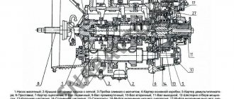
114. Installing the sealing ring of the shift shaft cover Install the rubber sealing ring into the hole under the axis of the selective lever 23 (see Fig. 105).
Rice. 105. Gear shift mechanism for cars of the UAZ-3741 family: 1-reverse fork rod; 2-reverse fork; 3-rod fork for selecting III and IV gears; 4-fork III and IV gears; 5-fork 1st and 2nd gears; 6-rod fork for 1st and 2nd gears; 7- cotter pin wire; 8 - plug; 9-washer; 10-shaft gear shift; 11-side cover; 12-gear clutch; 13-locking spring; 14-gasket; 15-oil seal cover; 16-shift lever; 17-cork; 18,20-clamp springs; 19-key plunger; 21-ball retainer; 22-gear selection lever; 23-selective lever; 24-pin; 25-reversing light switch; 26-plug
Install the clutch (Fig. 115), thrust washer, spring thrust cup and spring onto the shift shaft. Insert the shaft into the side cover body and install the oil seal cover with the gasket, secure the cover with three bolts.
Rice. 115. Gear shift shaft assembly
- Install the selective lever assembly with the axle (Fig. 116) into the cover body so that the lever fits into the groove of the shift clutch. Lock the lever with a pin, which is driven in from below.
- Turn the side cover over with the machined flange up and insert the springs and rod balls of the 3rd and 4th gears and the reverse rod into the sockets of the retainers (see Fig. 113).
Rice.
113. Device for assembling rods and clamps: a-assembly of the clamp; b-installation of the rod Install the reverse fork on the rod on the side opposite to the lock, and, having sunk the ball of the lock (Fig. 117) into the cover body using a mandrel (see Fig. 113), set the rod to the neutral position. So sequentially assemble all the rods (Fig. 118) and forks. Install locking blocks between the rods.
Rice. 117. Assembly of the rod and reverse fork Fig. 118. Assembly of the rod and fork for shifting 3rd and 4th gears
Secure the forks to the rods with conical bolts and pin them with wire (Fig. 119), which should not interfere with the movement of the forks. When attaching the forks, the shift clutch lever must be in the groove of the forks.
Rice. 119. Cotter pinning the bolts securing the forks with wire: 1-bolt; 2-pin-wire
- Insert the ball and the retainer spring into the hole in the rod of the 1st and 2nd gears and tighten the plug. Please keep in mind that the rod lock spring for 1st and 2nd gears in the free state is longer than the other two rod lock springs.
- Install six plugs into the end holes of the cover body, a plug into the hole for the shift shaft and hammer them out.
- Install the selection and shift levers (Fig. 120) onto the shaft splines and secure them with nuts and spring washers.
Rice. 120. Installation of external select and shift leversThe correct position of the levers is checked with the gears in the neutral position in the gearbox after installing the shift mechanism on the gearbox in accordance with Fig. 121.
Rice. 121. Position of the selection lever and shift lever after installing the mechanism on the gearbox: A - corresponding to reverse; B-corresponding to the inclusion of III and IV gears; B-corresponding to the inclusion of 1st and 2nd gears; 1-selection lever; 2-shift lever (in neutral position)
How to assemble a UAZ box
Disassembling a partially synchronized gearbox.
Disassemble in the following order:
Remove the side cover with the switching mechanism.
Remove the input shaft bearing cover
Turn the input shaft with the cutout towards the intermediate shaft drive gear and remove the input shaft with the rollers and the synchronizer blocking ring.
Unscrew the locking screw of the reverse gear block axle and press the axle back, removing the reverse gear block
Remove the plates securing the rear output shaft bearing.
Remove the synchronizer hub retaining ring (Fig. 5) and remove the secondary shaft back. In this case, all gears will be removed from the shaft, but the bearing will remain on the shaft.
Using a special wrench, unscrew the cover of the front bearing of the intermediate shaft.
Using a special wrench, unscrew the nut of the front bearing of the intermediate shaft and remove the intermediate shaft together with the bearing back. In this case, the drive gears of the 2nd and 3rd gears will be removed from the shaft.
Using a special wrench, unscrew the input shaft bearing mounting nut, which has a left-hand thread.
Remove the bearing from the input shaft using a puller
Remove the rear intermediate shaft bearing using a puller. The bearing mounting bolt has a left-hand thread and is secured with a disc spring.
Disassembling a synchronized gearbox
Disassemble in the following order:
Remove the side cover with the switching mechanism.
Using the M8 threaded hole in the rear end of the reverse idler gear axle, press the axle back and remove the gear.
Remove the input shaft bearing cap.
Remove the front intermediate shaft bearing cover.
Unscrew the rear intermediate shaft bearing mounting bolt (the bolt has a left-hand thread) and remove the bolt's disc spring.
Using a puller, remove the rear bearings of the primary and secondary shafts by their retaining rings.
Remove the rear intermediate shaft bearing retaining ring.
Install the box so that the intermediate shaft is at the top, move the intermediate shaft forward until the intermediate shaft gear block stops in the crankcase.
Move the intermediate shaft along with the rear bearing back until the inner race of the front bearing comes out of the rollers and the rear bearing comes out of the crankcase.
Remove the rear intermediate shaft bearing using a puller.
Install the gearbox with the hatch under the shift mechanism facing up.
Remove the input shaft, 4th gear locking ring, secondary shaft assembly (supporting the 1st gear spacer ring) and intermediate shaft assembly from the transmission housing.
Disassembling the secondary shaft
Remove the thrust washer and 1st gear with needle bearing.
Remove the synchronizer hub retaining rings using a puller and the thrust washer.
Remove the synchronizer for 1st and 2nd gears together with the 2nd gear gear.
Remove the retaining ring, key and 2nd gear bearing.
Remove the 3rd and 4th gear synchronizer together with the 3rd gear gear.
Remove the circlip, key, spacer and 3rd gear bearing.
Design and principle of operation
The gearbox diagram contains information about the main and additional elements of the system. The UAZ gearbox structure includes the following units and parts:
- Fully synchronized installation, ensuring speed equalization and smooth switching.
- Helical intermediate gears for shaft drive.
- An angular contact ball bearing, consisting of 2 rows and located on the rear of the shaft, is necessary to perceive and respond in a timely manner to loads arising during driving in the radial and axial planes.
- A transfer case consisting of a main axle shaft and a gear with a large working life.
Primary shaft on 2 supports.
Such design features make it possible to move in reverse. The mechanical type of gearbox has the main advantage of a long service life. A car with such a device copes well with difficulties while driving over rough terrain.
Malfunctions and repairs
The first signs indicating a malfunction of the automotive system should force the car owner to carry out diagnostics. In some cases, this can be done on your own. Simple breakdowns can be repaired with your own hands. It is better to entrust more complex faults to a service center.
Signs indicating the need to repair the UAZ gearbox:
In most cases, when uncharacteristic noise is observed, the cause lies in wear or defect of the bearings and gears. Stiff gear shifting indicates a malfunction of the synchronizers.
The main reason for the problems that arise is the natural wear and tear of parts.
The need to check the transfer case is indicated by deterioration in wheel adhesion to the road surface and increased noise levels from the area where the unit is located. Damage is caused by: careless operation of vehicles, untimely maintenance, use of low-quality consumables, fuel and gear oil, lack of control over the volume of working fluids.
Another group of problems is related to the leakage of the oil mixture from the gearbox. Possible reasons:
- exceeding the maximum oil volume in the box;
- water entering the system when refueling;
- a crack on the unit cover or on the crankcase.
The UAZ high-speed gearbox consists of a large number of working elements and components. Their normal functioning and interaction ensure reliable use of vehicles. Gearbox repairs will not be required if you regularly inspect your vehicle.
Mechanism adjustment
After assembling and installing the new switching mechanism, it is necessary to adjust the rods and the entire system. The goal is achieved by changing the length of the vertical and horizontal rods. Do-it-yourself setup sequence:
- Move the gear shift lever to the neutral position, and move the element responsible for selecting the gear all the way.
- Move lever 1 to positions corresponding to speeds 1 and 2. While checking that the elements are not pulled up, connect and secure the selection rod.
- Similar actions must be carried out for other gear stages.
After work, you should check that the gears are fully engaged by starting first gear and reverse. The lever must not come into contact with other parts or controls. The optimal gap size is up to 3 mm.
Source
Carrying out diagnostics of the UAZ 469 gearbox
The car is subject to diagnostics if its handling has deteriorated. At the same time, squeaking noises may be heard when changing gears. Also, it is necessary to check the condition of the box if the gears activate spontaneously. In some cases, it is necessary to replace bearings and gears to solve the noise problem. If gear shifting is difficult, the synchronizers are checked. The main reason why there is a need to replace the components of the box on an SUV is their natural wear and tear.
One of the signs that the transfer case should be checked is if the grip of the wheels on the road has deteriorated, and noise from its side has begun to increase. Improper use of the vehicle leads to repair of the gearbox on the UAZ 469. In particular, it is necessary to timely change the transmission oil.
Another problem that a UAZ driver may encounter is an oil leak from the gearbox. This manifestation is the result of an increased oil level in the gearbox. Also, if water gets into the system while filling the box with new fuel, the motorist will soon face the problem of fluid leaking from the gearbox. However, it is not only the use of low-quality oil that can cause leakage, since there may be a crack in the crankcase or in the UAZ 469 gearbox cover.
Thus, the high-speed gearbox of the UAZ 469 car includes many working units that ensure optimal functioning of the automotive system. Taking this into account, the owner of the vehicle must subject the car to regular maintenance. This will reduce the risk of premature repair of the UAZ 469 gearbox.