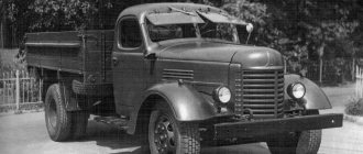
KamAZ is a Soviet-Russian automobile manufacturing company founded in 1976. Initially, it specialized in the production of trucks with a carrying capacity of 8 to 20 tons. The first truck to roll off the assembly line was the KamAZ 5320. The KamAZ engine was also developed from scratch specifically for this truck. The best foreign representatives were taken as its basis.
This is interesting! The correct spelling is not KAMAZ, but KamAZ, which stands for Kamsky (Kam) Automobile Plant (AZ). Since the KamAZ 740 engine has become the main one for this model, the focus of the article will be on this particular brand of engine.
Note!
There were many options for the KamAZ 740 engine. They differ primarily in Euro standards.
The name of such engines is approximately this: “KAMAZ 740-210 (260) engine.” It’s not particularly easy to remember numbers, so people often hear such names as “KAMAZ Euro 2 (3.4) engine.”
Since there can be several KamAZ engines of the same European standard, the tables with technical characteristics will indicate the factory name.
General characteristics of the KamAZ 740 engine series
The first engine of this family is considered to be a simple KamAZ 740 V8 engine.
This is interesting!
In the engine designations in the future, you may come across various designations for engine types. So, the English letter V means V-shaped engine. This means that the cylinders are arranged in two rows and the angle between the rows is less than 90 degrees.
In an L-shaped engine, the cylinders are also arranged in 2 rows, but at an angle of approximately 90 degrees. The English letter R in the name indicates that the engine is in-line. That is, the cylinders are located next to each other. Powerful eight-cylinder engines often have a V-shaped structure, while ordinary passenger car engines have an R-shaped structure.
Initially, the KamAZ 740 engine had an engine capacity of 10,852 cm3, with a power of 210 horsepower. Only then did later modifications come out, which had a power range from 180 to 360 horsepower.
The use of diesel fuel in the engine was far from new for trucks. This is fully justified by lower fuel consumption, improved lubrication and increased power, but for a novice driver, familiarity with engines of this type will be new.
- Firstly, there is a significantly increased compression ratio. So, on a VAZ 2107 car the compression ratio is 8 units, and on this diesel engine as much as 17!
- This is also the absence of spark plugs, which is also at least unusual. The mixture in diesel engines ignites due to high pressure. Let's remember school physics. There are 3 interrelated parameters. Temperature, pressure and volume. Thus, with a decrease in volume, a sharp increase in pressure and temperature occurs. Based on this law, a diesel engine operates.
INTRODUCTION
Joint Stock Company (JSC) KamAZ produces vehicles with 6×4, 4×2 and 6×6 wheel arrangements, differing in power, size and weight parameters. Mass production of KamAZ family vehicles and their entry into the country's motor transport complex began in 1976. During production, the design of vehicles and their components was improved, their quality increased, and best operating and repair experience was accumulated and studied.
This course work describes in detail the design of the crank mechanism in the 740.10 engines of the KamAZ vehicle. The technical characteristics of the engine are given in Table 1. In terms of its environmental performance, the 740.10 engine meets the requirements of UNECE rules at the EVRO-2 level. All necessary recommendations from the manufacturer on adjustments of the engine and its systems, main faults, methods for their detection and elimination are provided.
The purpose of the course work is to study the design of the crank mechanism of the KamAZ 740.10 engine
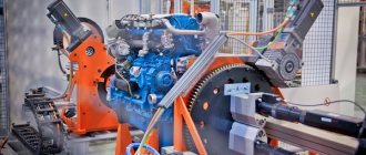
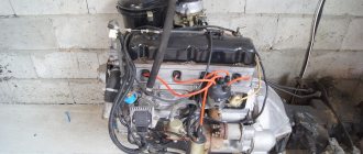
Engine KamAZ 740
What advantages does it have over similar engines of other brands, both domestic and foreign:
- The design of the KamAZ engine makes it smaller than many domestic analogues and more reliable than foreign ones. This is a kind of “golden mean” between large, gluttonous, low-power and reliable engines of Soviet/Russian production and powerful, economical (in terms of a liter of fuel per horsepower), but not so reliable and durable.
- Another advantage of the engine is that it is quite easy to start in the cold season, since these KamAZ engines are equipped with a very powerful battery and starter, which are complemented by a cold engine warm-up system.
Technical characteristics of Euro class motors
- MOTOR KAMAZ EURO 0
The KamAZ Euro 0 engine is considered the very first engine of the family. The most famous motor of the 740 series. It is good and reliable. But its problem is its non-compliance with the latest European standards.
Table KamAZ engine Euro 0
Download .xls file xls Download picture pic Send to email mail
| Engine model | 740-210 | 740-260 |
| Engine power, kW (hp) | 154(210) | 191(260) |
| Engine speed | 2600 | 2600 |
| Maximum torque, Nm (kGm) | 667(68) | 765(80) |
| Number and arrangement of cylinders | 8, V-shaped | 8, V-shaped |
| Cylinder diameter/piston stroke, mm | 120/120 | 120/120 |
| Engine displacement, l | 10.85 | 10.85 |
| Compression ratio of the fuel mixture | 17 | 16.5 |
| Cylinder operating order | 1-5-4-2-6-3-7-8 | 1-5-4-2-6-3-7-8 |
| Direction of rotation of the crankshaft according to GOST 22836-77 | right | right |
| Complete engine weight (gross) according to GOST 14846-81, kg | 750 | 780 |
| Lubrication system filling capacity, l | 26 | 28 |
| Cooling system capacity (motor only), l | 18 | 18 |
| Injection pump model | 33 YAZDA | 334 YAZDA |
| Engine injector | 271 | 271 |
| Injection start pressure, MPa | 21,3-22,3 | 22,95-23,73 (234-242) |
This is interesting: Priora sedan equipped with ESC
- ABOUT THE KAMAZ EURO 2 ENGINE
More modern and modified Euro 2 KamAZ engines. The first KamAZ 740 engine is inferior to the Euro 2 engine, primarily due to the modern design of components and assemblies, as well as other European requirements.
A total of 4 Euro 2 class motor models were produced. All of them, along with detailed technical characteristics, are presented below in the tables.
Table Engine KamAZ Euro 2. Part 1
Download .xls file xls Download picture pic Send to email mail
| Engine model | 740.31-240 | 740.30-260 |
| Power, kW (hp) | 176(240) | 191(260) |
| Engine speed | 2200 | 2200 |
| Maximum torque, Nm (kGm) | 980(100) | 1078(110) |
| Number and arrangement of cylinders | 8, V-shaped | 8, V-shaped |
| Cylinder diameter/piston stroke, mm | 120/120 | 120/120 |
| Engine displacement, l | 10.85 | 10.85 |
| Combustion chamber compression ratio | 16 | 16.5 |
| Cylinder operating order | 1-5-4-2-6-3-7-8 | 1-5-4-2-6-3-7-8 |
| Direction of rotation according to GOST 22836-77 | right | right |
| Complete motor weight (gross) according to GOST 14846-81, kg | 760 | 885 |
| Lubrication system filling capacity, l | 26 | 28 |
| Cooling system capacity (motor only), l | 18 | 18 |
| Injection pump model | 337-20 YAZDA | 337-71 YAZDA |
| Engine injector | 273-51 | 273-51 |
| Injection start pressure, MPa | 21,3-22,5 | 21,4-22,4 |
Table Engine KamAZ Euro 2. Part 2
Download .xls file xls Download picture pic Send to email mail
| Engine model | 740.51-320 | 740.50-360 |
| Engine power, kW (hp) | 235(320) | 265(360) |
| Crankshaft rotation speed, min -1 | 2200 | 2200 |
| Maximum torque, Nm (kGm) | 1020(104)) | 1147(117) |
| Number and arrangement of cylinders | 8, V-shaped | 8, V-shaped |
| Cylinder diameter/piston stroke, mm | 120/130 | 120/130 |
| Engine displacement, l | 11.76 | 11.76 |
| Combustion chamber compression ratio | 16.5 | 16.5 |
| Cylinder operating order | 1-5-4-2-6-3-7-8 | 1-5-4-2-6-3-7-8 |
| Direction of rotation of the crankshaft according to GOST 22836-77 | right | right |
| Complete motor weight (gross) according to GOST 14846-81, kg | 885 | 885 |
| Lubrication system filling capacity, l | 28 | 28 |
| Cooling system capacity (motor only), l | 18 | 18 |
| Injection pump model | 33720-03 YAZDA | 33720-04 YAZDA |
| Engine injector | 27350 | 27350 |
| Injection start pressure, MPa | 23,34-24,52 | 23,34-24,54 |
- MOTOR KAMAZ EURO 3
KamAZ Euro 3 engines are basically a transitional link from Euro 2 and Euro 4 engines, so the article will not contain their detailed characteristics.
- MOTOR KAMAZ EURO 4
Table Engine KamAZ Euro 4
Download .xls file xls Download picture pic Send to email mail
| Engine model | 740.70-280 | 740.71-320 | 740.72-360 | 740.73-400 | 740.74-420 | 740.75-440 |
| Location and number of cylinders in the engine | V-8 | |||||
| Cylinder diameter and piston stroke, mm | 120130 | |||||
| Engine displacement, l | 11.76 | |||||
| Combustion chamber compression ratio | 16.8 | |||||
| Maximum net engine power according to UNECE Rules No. 85-00, rated net power according to GOST 14846-81, l. pp., no less | 280 | 320 | 360 | 400 | 420 | 440 |
| Rated crankshaft rotation speed, min -1 | 1900 | |||||
| Maximum net torque of the motor according to UNECE Rules No. 85-00, maximum net torque according to GOST 14846-81, kgf*m, not less | 1177 | 1373 | 1570 | 1766 | 1864 | 2060 |
| Crankshaft rotation speed corresponding to maximum torque, min -1 | 1300 +/- 50 | |||||
| Minimum specific fuel consumption, g/(hp*h) | 194.5 | |||||
| Oil consumption for waste at rated power mode, % of fuel consumption | 0.06 | |||||
| Weight of the engine not filled with lubricant in the delivery set, kg | 870 | |||||
| Dimensions: Length x Width x Height, mm | 1260x930x1045 |
- CUMMINS (KAMENS) KAMAZ ENGINE
Kamens engines are foreign engines installed on KamAZ trucks of our production. In terms of power characteristics, they are equal to the Russian 740, not inferior to the latter either in reliability or power.
At KamAZ, Kamens engines have established themselves as a worthy, albeit more expensive, alternative to the Russian engine, the legendary 740.
Device Description
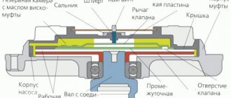
The generator set is one of the main components of a car. It provides power to the vehicle's single-wire electrical circuit while the engine is running. Its design includes a generator and a voltage regulator (the author of the video is yuriy s).
The unit is located at the top of the engine at the front. It is held by 3 paws. Two of them secure the device to the bracket, the third claw serves as a fastener to the tension bar. Driven by V-belts. They must have the rated voltage, otherwise the device will not work effectively. Therefore, two belts are installed on KAMAZ vehicles.
Principle of operation
The voltage from the battery is transmitted to the field winding thanks to brushes and slip rings, provided that the instrument switch is turned on and the starter is in position “I” or “II”. A magnetic field arises around it, due to which plus and minus appear on the rotor, corresponding to the south and north poles. When the rotor starts working, the magnetic flux changes simultaneously with it. It crosses the windings of the stator coils, in which alternating current arises and enters the rectifier block. In the block it becomes permanent.
Functions performed
To start the generator set, you need a battery. When the voltage generated during operation of the unit exceeds the battery voltage, the unit will begin to supply power to consumers and charge the battery.
Thanks to the voltage regulator and generator, the on-board network voltage is maintained within acceptable limits.
Technical specifications
The G273-A generating set has a rated voltage of 24 V and a power of 800 W. The rated voltage of the G288 generator is 28 V, and the power is 1000 W. The G288 generator is installed on KAMAZ 5320. There are other models of generators.
Device components
The main elements of the generator are the stator (2) and the rotor (5). In addition, the design includes covers (8), a brush assembly (1) and a rectifier block. The shaft on which the field winding is located rotates on 2 ball bearings. At one end of the shaft there are slip rings that are connected to the winding, at the other there is a fan (6) and a 2-strand pulley (4). The brushes slide along the rings. The rectifier block and brushes are located in the cover.
The voltage regulator is equipped with a seasonal switch. At temperatures below zero degrees, the switch occupies the extreme right position, and at temperatures above zero - the extreme left position.
Operating principle of the KamAZ 740 engine
This section will also be collective, since all engines of the 740 family have approximately the same operating principle:
- The main part of the engine is the cylinder block, which is made as a single monoblock and is a collective part on which all the main engine parts are attached.
- The crankshaft is located in the center, but with a significant shift downward. Below it is the crankcase, where the oil is located during idle times. You need to pour 26-28 liters of oil into the engine. This is exactly the volume of the crankcase. We will look at the oil change process below.
- The number of valves per cylinder is two. One inlet and one outlet. Otherwise, the operating principle of the engine is the same as other diesel engines.
This is interesting: Tire puncture repair
Marking
The abbreviated model designation in the form of an eight-digit code - the identification number of the engine and modification (740.ХХ-ХХХ) - is applied in two lines to the untreated surface of the cylinder block.
In official documents, engines are indicated with additional numbers that reflect:
- configuration data;
- high pressure fuel pump model;
- applicability.
Marking examples:
- 740.11-1000400 – basic set with injection pump YAZDA 337-40 (injector 273-51 with 5 nozzles) for KAMAZ 55111, 53215;
- 740.11-1000412-58 – set with injection pump YAZDA 337-1111005-42.08 (337-42) for KAMAZ-43114, etc.
Maintenance of engines of the KamAZ 740 family
The KamAZ 740 engine is diesel and therefore it is very difficult to repair it at home, but some small things can be done. Such things include changing the coolant and oil.
Coolant replacement
Coolant must be replaced every 3-5 years depending on operating conditions. The need to replace the coolant is indicated primarily by the fact that the coolant itself has lost its original color and has become the color of dirty water.
The KamAZ 740 engine is filled with Tosol-A40 type coolant with a total volume of 25 liters.
You need to constantly monitor the coolant level. It is advisable to check this level every time you start the engine. This is done quite simply:
- You just need to open a special tap on the expansion tank. If antifreeze begins to flow, then the level is normal. Close the tap and start the engine. If nothing flows from the tap, then you need to add coolant, and if nothing happens when adding, you need to check first the tap itself, and then the entire cooling system, coolant leaks are possible.
- If there is a shortage of coolant, do not start the engine under any circumstances. Otherwise, not just antifreeze, but antifreeze with water will circulate in the cooling system. This can lead to destruction of the impeller and costly repairs overall.
- If the fluid has leaked, but its condition leaves much to be desired, then it must be replaced. To do this, drain the liquid from the lower tap of the radiator, boiler and heater pump unit, and the cabin heater supply pipe.
- After this, close all taps and fill the system with coolant.
Change of oil
Oil, like coolant, requires periodic replacement. The oil level is checked, as on all engines, with a special dipstick. The lubricant level should be about o.
Excess, just like less oil, is not advisable. If there is too little oil in the engine, then the wear of all engine parts will sharply increase, since they will run almost “dry”. It is better not to start an engine that does not have enough oil to avoid serious damage. It's best to find and add oil.
If this cannot be done, then reduce the load on it as much as possible. Remove excess cargo and unhitch the trailer. If this is also not possible, then it is better to wait for help. Driving a loaded car with this level of oil can lead to very serious consequences.
If the oil still needs to be changed:
- Warm up the engine to a temperature of 80-90 degrees Celsius;
- We turn off the engine;
- We unscrew the plug on the crankcase (photo below);
- We wait until the oil is completely poured out;
- We change filter elements;
- Wash the rotor of the centrifugal oil filter;
- Fill the oil through the special filler neck up to about on the dipstick;
- We start the engine and let it idle for 5-10 minutes;
- Turn off the engine, and after 5-10 minutes add oil to about on the dipstick;
- After this, the oil change process can be considered complete.
3. Disassembly, repair and assembly of the connecting rod and piston group
Before the warranty period expires, do not disassemble the engine (do not remove the cylinder heads, oil sump, do not break the seals of the high-pressure fuel pump and do not disassemble it), otherwise the right to warranty repair of the engine will be lost. If necessary, it is allowed to replace high and low pressure fuel lines, hoses, oil, fuel and air filters, water pump, fan, fluid coupling switch, external fasteners, intake air lines and exhaust manifolds, water collection pipes, injectors, pushrods, turbochargers;
For disassembly, it is recommended to use a rotary stand R-770, on which the engine has the ability to rotate around the vertical and horizontal axis.
Before installing the engine on the stand, remove the oil filter with heat exchanger, fan, exhaust manifolds, front support brackets, and starter. Lubricate the rubbing surfaces of parts, unless otherwise specified, with engine oil during assembly.
For ease of assembly, install non-metallic gaskets, if necessary, with grease applied to one of the mating parts. Make sure that the gaskets evenly adhere to the mating surfaces, are tightly clamped and do not protrude beyond the contour of the mating surfaces [4, p. 10].
When installing, lubricate the rubber sealing rings and lead-in chamfers of the mating parts with grease;
Do not bend the pins when putting parts on them.
The piston with rings and connecting rod assembly is installed in a vice and, using a puller I-801.08.000, the upper compression ring, compression ring and oil scraper ring assembly are removed from the piston. If it is necessary to replace the piston or connecting rod, remove the piston pin retaining ring from the piston bosses and remove the piston and connecting rod assembly from the vice.
After heating the piston for 10 minutes in an oil bath to a temperature of 80...100 °C, press out the piston pin using a drift. Parts of the connecting rod and piston group are washed and defective.
The piston is rejected if there are cracks, burnouts, destruction of the bottom, inclusion of foreign particles, as well as wear:
- piston skirts in a plane perpendicular to the axis of the pin, at a distance of 104 mm from the bottom - to a size of less than 119.81 mm;
— holes for the piston pin — up to a diameter of more than 45.02 mm;
- grooves of the upper compression ring - up to a size measured by rollers with a diameter of 2.96 mm inserted into the groove, less than 120.25 mm;
- grooves of the lower compression ring - to a size measured similarly, less than 120.7 mm;
— oil scraper ring grooves — up to a height of more than 5.1 mm;
— outer surface — up to a diameter of less than 44.99 mm.
The piston pin is rejected if there are chips, cracks, scratches, nicks and traces of corrosion on the surface and ends, as well as if the outer surface is worn to a diameter of less than 44.99 mm. In the latter case, the part should be sent for restoration [4, p. 10].
The connecting rod assembly is rejected if there are cracks or breaks, wear of the ends of the lower head along the width to a size of less than 33.23 mm. The bending and twisting of the connecting rod is determined using device 30701. If the axes of the connecting rod head holes are not parallel over a length of 100 mm by more than 0.06 mm, the connecting rod is rejected or sent for restoration.
If the hole in the bushing of the upper head of the connecting rod is worn out to a diameter of more than 45.04 mm, the bushing is pressed out and a new bronze bushing is installed so that the oil holes in the bushing and connecting rod coincide. Before installation, the bushing is cooled to a temperature of minus 50 ° C. Pressing the bushing is not allowed. The hole in the installed bushing is bored to a diameter of 45+8; 4 mm at a boring head rotation speed of 1600 min and a feed of 0.06 mm/rev. The restored connecting rod is washed and blown with compressed air. If the hole in the upper head of the connecting rod for the bushing is worn to a diameter of more than 49.02 mm, the connecting rod is rejected or sent for restoration. If the hole in the lower head of the connecting rod is worn to a diameter of more than 85.02 mm, it is processed to a repair size of 85.5 mm, and if the diameter is more than 85.535 mm, it is rejected or sent for restoration.
Before assembling the connecting rod and piston group, the piston pins are selected to the connecting rods. The piston is heated in oil to a temperature of 80...100°C, placed in an assembly device and connected to the connecting rod with a piston pin, installing the connecting rod so that the recesses for the valves in the piston and the grooves for the whiskers of the liners on the connecting rod are located on one side. Pressing in the piston pin is not permitted. Before assembly, the mating surfaces of the piston pin and the holes in the piston are lubricated with a thin layer of clean motor oil M YuGgk [4, p. 11].
The piston pin retaining rings are installed in the piston grooves. Using a device for removing and installing rings, the oil scraper and compression rings are sequentially installed on the piston (Fig. 10). When installing the oil scraper ring, install an expander into the piston groove and then put on the oil scraper ring so that the joint of the expander is diametrically opposite to the ring lock. Compression rings are installed on the piston with the beveled side and the “top” mark towards the piston bottom. The locks of adjacent rings are positioned at an angle of 120 °C. Before installing the rings, remove carbon deposits from the piston grooves, and after installation, check the ease of movement of the rings in the grooves.
The connecting rod must also move freely around the piston pin axis. If these requirements are met, the piston and connecting rod assembly is removed from the fixture and transferred to engine assembly.
Fig. 11. Disassembling the cylinder head in device I-801.06.000
1 - screw; 2 — handle; 3 — valve plates; 4 - pin; 5 - cylinder head.
The cylinder head is installed on a disassembly/assembly jig 7831-4044 or a workbench. Having straightened the antennae of the lock washer for fastening the rocker arm, unscrew the nuts securing the rocker arm axle posts and remove the rocker arm, lock washers and rocker arm retainer, and then the valve rocker arms from the rocker arm. Having unscrewed and removed the nut 10 of the adjusting screw, screw in the adjusting screw 8 of the rocker arm, remove the cylinder head from the disassembly-assembly device and install it on the device for removing and installing valves (Fig. 11) so that the pins 4 fit into the holes for the head mounting bolts.
By rotating the handle of the device, press out the valve spring plates together with the bushings and remove the valve cotters, plates with bushings, outer and inner springs and valve spring washers. The sealing collar assembly is removed from the intake valve guide bushing, after which the intake and exhaust valves are removed from the cylinder head [4, p. 13].
If replacement is necessary, remove the following parts: intake manifold mounting screw, water pipe mounting screw, exhaust manifold pipe mounting studs, rocker arm mounting studs and injector bracket mounting studs. The cylinder head is removed from the fixture.
The cylinder head and the removed parts are washed, the valves, seats and valve guides are cleaned of carbon deposits, the parts are blown with compressed air and defects are removed.
The cylinder head is installed on a crimping stand 470.085 and checked under an air pressure of 0.3 MPa (3 kgf/cm) for 2 minutes for tightness of the cooling jacket and under a pressure of 0.6...0.65 MPa (6...6.5 kgf/cm ) — tightness of oil channels. If there is an air leak, the cylinder head is rejected. It is also subject to rejection in the presence of cracks involving internal channels, cavities of holes for the injector, guide bushings and the mating surface with the cylinder block, in case of destruction of seats for valve seats and jumpers between them, in case of damage or gravitational destruction of the mating surface with the cylinder block [4 , p.14].
If there are grooves or cavities on the working surface of the valve seats, they are processed until the defect is removed by lapping, not allowing the diameter of the exhaust valve seat to increase more than 43 mm, and the intake valve seat - 48 mm. If it is impossible to eliminate the defect, the seats are replaced.
If there are cracks, chips, mechanical damage on the surface of the valve guide bushings, as well as if the hole in the guide bushing is worn to a diameter of more than 10.04 mm, the bushing is replaced. The gas joint sealing ring must also be replaced if it burns out or is mechanically damaged.
The cylinder head cover is rejected if there are breaks or cracks. The flatness of the contact surface to the cylinder head is checked with a feeler gauge on the surface plate. It should be no more than 0.15 mm. Otherwise, the surface is treated until the defect is eliminated, removing a layer of metal no more than 0.5 mm. If it is impossible to eliminate the defect, the part is rejected.
The valve rocker arm with the bushing assembly is rejected if there are breaks or cracks, as well as if the toe of the rocker arm is worn in height. The distance from the horizontal line passing through the center of the hole in the rocker arm bushing to the toe of the rocker arm should be no more than 6.0 mm. If the hole in the bushing wears out, it is replaced and machined to a repair size in accordance with the repair size of the rocker arm strut.
The rocker arm strut is rejected if there are breaks or cracks. When the supporting surfaces are worn, they are processed to repair size; if the diameter is more than 24.66 mm, they are rejected.
The intake and exhaust valves are rejected if there are cracks, breaks, wear or burnout of the valve working chamfer. If the intake valve stem is worn to a diameter of less than 9.94 mm, and the exhaust valve is less than 9.90 mm, the valve is rejected or sent for restoration. If there is uneven wear on the end of the valve stem, it is processed until the defect is eliminated, without allowing
reducing the height from the end to the annular groove beyond 6.3 mm. If it is impossible to eliminate the defect, the valve is rejected.
After eliminating the defects, the cylinder head assembly with valve guides is placed on a disassembly-assembly device 7831-4044 or a workbench and the following parts are installed in place, if they were removed: studs for fastening the exhaust manifold pipe (the protrusion height of the studs is 52 ± 1 mm) , injector bracket mounting studs, rocker arm mounting studs, intake manifold mounting screw and water pipe mounting screw. The cylinder head is removed from the assembly device and installed on a stand for lapping valves with the valve seats facing upward [4, p. 15].
Having prepared a lapping paste from 81% granular electrocorundum and 13% paraffin, diluted in MUGgk engine oil to a creamy state, apply the paste to the working surface of the valve seats. Having installed the intake and exhaust valves in the cylinder head, grind them in until a continuous matte belt with a width of at least 1.5 mm without marks or tears on the surface of the belt appears on the chamfers of the valve and seat. When properly lapping, the matte band on the seat should start at the base of the large seat cone.
The cylinder head and valves are placed in containers, the cells of which are numbered and ensure that the belonging of the valves and seats to which they are ground is preserved. The parts are washed in KM-1 washing solution with EAP-40 defoamer. Concentration of KM-1 is 5 g/l, EAP-40 is 0.2...0.3%. Composition of the washing solution: sodium carbonate - 22.5%, trisodium phosphate - 18.9%, sodium tripolyphosphate - 50.6%, sulfonal - 2.3%, synthanol DT-7 - 5.7%. The temperature of the washing solution is 70...80 °C, holding time is 2 minutes.
After washing, the cylinder head is installed on the device for removing and installing valves (see Fig. 11), the valve stems and working surfaces of the guide bushings are lubricated with clean engine oil, and the valves are installed in their places according to the numbering after grinding.
A sealing collar assembly is installed on the intake valve guide, valve spring washers, internal and external springs, valve spring plates with bushings are installed, and by rotating the handle, the devices compress the springs with the discs and bushings. Having installed the valve cotters, release the springs making sure that the cotters fit into the bushing.
After removing the cylinder head from the device, check the tightness of the valves. To do this, the cylinder head is installed alternately with the intake and exhaust ports facing up and diesel fuel is poured into them. Well-lapped valves should not leak fuel at the sealing points for 30 seconds. If fuel leaks, tap the end of the valve with a rubber hammer. If leakage persists, the valves must be ground in again. The quality of the grinding can be checked with a pencil, for which six to eight lines are applied across the valve chamfer at an equal distance. The valve is inserted into the seat and, pressing firmly on it, is turned 1/4 turn. With good grinding, all lines should be erased.
Malfunctions
If the engine does not start, see the table below:
| Cause of malfunction | Remedy |
| No fuel in tank | Fill the fuel tank and be sure to bleed the fuel system. |
| Presence of air in the fuel supply system | Fix the leak and then bleed the system. |
| Failure to adjust the fuel injection advance angle | Adjust the lead angle. |
| Freezing of water that gets into the fuel pipes or onto the fuel tank intake screen | Warm fuel filters, tanks and pipes carefully with a rag soaked in steam or hot water; do not use open fire for heating. |