The wheeled tractor MTZ-81.1 23/12 “Belarus” is a universal agricultural machinery that is intended for agricultural work with trailed, semi-mounted and mounted machines and equipment. It is worth buying a tractor MTZ 82.1-23/12 “Belarus” (beam) for agricultural, municipal, forestry, and construction work. This is a wheeled universal row crop tractor. It can be used with heavy-duty loading equipment, larger snow buckets to remove snow. The unit can also be equipped with brushes and a communal dump for garbage collection.
KAMAZ gearbox device
The gearboxes that KAMAZ vehicles are equipped with are fundamentally no different from similar units of other tractors. However, they are not interchangeable and have certain design features.
The most common two variants of the KAMAZ gearbox are the 14th (141, 142, 144) and 15th (152, 154) models.
Three shafts are installed in the crankcase of both boxes:
- leading;
- intermediate;
- slave.
Like any modern manual transmission, they are equipped with synchronizers and have a gear transmission. Reverse gears are installed in a separate block. The speed change mechanism is located in a separate block, which is located in the upper part of the box.
Beam bridge: what are its features
Front axles for Belarus tractors are made of two types - beam and portal. The first is distinguished by fixed track dimensions, and the ground clearance is slightly lower than that of the second. Among the main features are increased rigidity and strength, so the structure is able to withstand excessive loads (from 1 ton or more).
But due to the fact that the track is fixed, the possibility of using the tractor for many agricultural works is excluded. But on the other hand, it effectively copes with activities in the field of forestry, housing and communal services, and construction work. In other words, such a tractor can be sent to places where there is no need for high ground clearance. A tractor with such equipment shows excellent resistance to long-term and significant loads. The beam bridge has a rather complex design, but excellent performance characteristics, so that it is able to cope with the assigned tasks even in the most difficult conditions.
KAMAZ gearbox divider device
A divider is a mechanism that reduces the gear ratio of a gearbox.
Its design includes the following components:
- synchronizer blocking rings installed on both sides;
- a clutch with teeth that synchronizes the rotation of elements;
- two gears;
- two shafts;
- frame;
- gear shift fork;
- lever arm;
- fork roller.
To reduce wear and increase service life, parts operate in an oil environment.
If you are planning to independently repair a KAMAZ gearbox with a divider, the device diagram should be well studied and be at hand.
Signs of malfunctions in the power steering system
There are several signs that the power steering system is airy, in which case it is necessary to bleed it. Among them:
- the appearance of strong noise in the area where the power steering or its pump is installed;
- increased pressure on the steering wheel , difficulty turning it;
- leakage of working fluid from the power steering system.
In addition, there are several other signs that indicate the system is becoming airy - the appearance of foam on the surface of the working fluid in the expansion tank, spontaneous turns of the steering wheel to one side. If you encounter at least one of the described symptoms, it means you need to bleed your power steering.
Common faults
In general, repair of the hydraulic power steering on KamAZ trucks is required very often, since it is a fairly reliable system. Especially if the rules for using the node are followed and its scheduled maintenance is performed.
- The power steering began to lose oil from the hydraulic system;
- The steering wheel stopped turning easily in one direction or the other, and began to turn with difficulty;
- There are extraneous noises or loud noises when the pump is running;
- The steering wheel began to linger on its return stroke;
- It has become difficult to hold the steering wheel when driving straight;
- Some shocks began to be transmitted to the steering wheel ;
- The steering wheel turns quickly , but the steering mechanism itself is slow or difficult to respond.
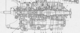
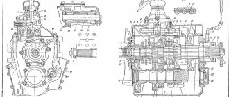
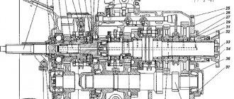
KAMAZ gearbox diagram with divider
| 1 | Nut M12x1.25-6N | 28 | Spring washer 8 |
| 2 | Lock washer 12.3 | 29 | Gear divider housing hatch cover |
| 3 | Front intermediate shaft bearing cover | 30 | Crankcase stud M16x1.5x22x45 |
| 4 | Lock washer 10 | 31 | Spring washer 16 |
| 5 | Bolt M10x1.25-6gx30 | 32 | Nut M16x1.5-6N |
| 6 | Input shaft bearing cover assembly | 33 | Gear divider synchronizer assembly |
| 7 | Input shaft cover gasket | 34 | Gear divider housing gasket |
| 8 | Adjusting gasket | 35 | Gear divider intermediate shaft assembly |
| 9 | Adjusting gasket | 36 | Intermediate shaft rear bearing seat |
| 10 | Gear divider primary shaft assembly | 37 | Screw M6-6gx16 |
| 11 | Special nut M52x2-L-6N | 38 | Roller bearing |
| 12 | Primary shaft oil injection ring | 39 | Upper clutch housing cover |
| 13 | Pin 4x12 | 40 | Gear divider intermediate shaft |
| 14 | Radial roller bearing with long cylindrical rollers, double row, without rings | 41 | Intermediate shaft gear |
| 15 | Retaining ring | 42 | Gear divider with control assembly |
| 16 | Single row radial ball bearing GOST 520-89 | 43 | Pin 12x35 |
| 17 | Gear divider primary shaft | 44 | Hairpin M16x1.5x22x35 |
| 18 | Prismatic key 6x8x13 | 45 | Single row radial ball bearing with a groove on the outer ring |
| 19 | Primary shaft rear bearing bushing | 46 | Front bearing thrust ring |
| 20 | Gear divider input shaft gear assembly | 47 | Thrust washer |
| 21 | Drain plug with magnet assembly | 48 | Hairpin M12x1.25x18x30 |
| 22 | Gear divider housing with bushings assembly | 49 | Locking bar |
| 23 | Oiler KG/8″ 45 (45916751064) | 50 | Bolt M12x1.25-6gx30 |
| 24 | Eye bolt | 51 | Front intermediate shaft bearing cover gasket |
| 25 | Plug 28 | 52 | Bearing cap sealing ring |
| 26 | Pad | 53 | Lower clutch inspection hatch cover |
| 27 | Bolt M8-6gх16 | 54 | Clutch housing cover |
GEARBOX, GEARBOX REPAIR
When checking the pneumatic system for leaks, determine the location of the air leak by ear.
Alternately moving the control switch to the HIGH GEAR or LOW GEAR position, listen to the air lines of the splitter control pneumatic system, and by pressing the clutch pedal all the way, listen to the air lines of the splitter switching system. Eliminate any detected leakage by tightening the bolts or replacing sealing washers and faulty air lines.
Adjust the engagement of the gear divider synchronizer gear couplings with compressed air supplied to the pneumatic system and the divider activation valve pressed all the way as follows:
— remove the seals, unlock and unscrew two setscrews 1 and 5 (Fig. 146) on the housing of the divider gear shift mechanism and remove cover 3 of the inspection hatch;
— move the spool of the divider control valve to the LOW GEAR position and, screwing in the rear set screw 5 until it comes into contact with the lever, tighten it another 1/4 turn and lock it with lock nut 4.
In this position, the drive shaft (with the gearbox removed) should turn easily by hand, without jamming;
— move the spool of the divider control valve to the HIGH GEAR position and adjust the engagement using the front set screw 1 as indicated above;
— through the inspection hatch in the housing of the divider gear shift mechanism, check the operating stroke of the lever until it stops at the set screws (16.5...19 mm in the center of the hole in the lever);
— lock and seal the set screws 1 and 5.
When repairing the remote transmission control drive, to reduce the effort when shifting gears, replace the lubricant in the three drive supports and the spherical heads of the lever joints.
Pump fresh lubricant into the supports through grease fittings, screwing them in instead of the plugs in the support housings.
If, after lubricating the supports, the force on the lever when shifting gears has not changed or has not decreased sufficiently, disassemble the supports in the following order:
— Unscrew bolts 19 (see Fig. 138) securing the adjusting flange; Unscrew the bolts securing the support on the clutch housing;
— remove the rubber cover of the hinge joint, paying attention to the safety of the limit ball and spring;
— unscrew the adjusting flange 18 from the intermediate rod and pull the intermediate rod out of the support;
— disconnect head 6 of the front linkage, paying attention to the safety of the ball and spring;
— disconnect covers 15 from the support located in the flywheel housing;
— remove the front link located in the camber of the cylinder block;
— remove the gear shift lever support located on the front end of the block, as described below. Remove the crackers 11, bushings 18, and spring 14 from the support housings.
Wash the parts and cavities of the supports with kerosene or diesel fuel, replace worn o-rings. When assembling, lubricate the rubbing surfaces with lubricant 158; apply fresh lubricant
in the cavity of the supports. After assembly, adjust the remote drive.
To adjust the remote control drive of the gearshift mechanism of models 14 and 15:
— set the gearshift lever to neutral position;
- loosen the tightening bolts 24 (see Fig. 138) of the tightening adjusting flange 18, unscrew the four connecting bolts 19 and screw the adjusting flange one or two turns onto
intermediate rod 17;
— unscrew the locknuts 8 and 22 of the set screws 9 and 21. Lock the tip lever 7 and the rod lever 23 by screwing the set screws into the holes of the levers;
— unscrewing the adjusting flange until its end comes into contact with the end of the rod flange along the entire plane, connect them with four bolts 19. Secure the flange to the intermediate rod by tightening bolts 24;
— turn out the set screw 9 located on the front support of the gear shift lever by 31 mm, and the set screw 21 located on the rear support of the lever by 16 mm. After
To do this, lock them with locknuts.
To remove and disassemble the gearshift lever support
tilt the cab, remove the noise-insulating cover of the gear shift lever, parts of the support seal, disconnect the air ducts
pneumatic system of the divider (gearbox model 15), generator mounting bracket, rods and fuel pump control cables, remove head 6 (see Fig. 138) of the front link, remove the bolts
fastening the support bracket to the engine and remove the support, disconnect valve 1 of the divider control and the gear shift lever.
Disassemble the support in the following sequence: remove the rubber boot 14 (see Fig. 139), cap holder 9, brake spring, pressure disc 6, brake disc 8, unscrew nut 15, remove spring 10
and pressure washer 11, remove the lever tip 4, remove the pins 16 and the axis 12 of the lever tip.
Wash the parts, lubricate the rubbing surfaces with lubricant 158. When assembling, tighten nut 15, align its groove with the groove of the bracket and open it. Fill cavity A of the support with lubricant 158.
The tip 13 of the lever must be rotated in mutually perpendicular directions with a force of 24.5...34.3 N (2.5...3.5 kgf) applied to the conical surface of the tip of the lever.
To adjust the gaps between the divider synchronizer carriage and the gear divider shift fork nuts
remove cover 6 (see Fig. 137) of the inspection hatch of the divider housing. Unlock
and unscrew the two bolts securing the gear shift mechanism fork in the divider so that the shaft 13 with the lever 16 mounted on it moves freely in the axial direction, remove the divider shift mechanism.
Center the drive shaft 2 of the divider using a special device, which consists of a housing with a centering device and two clamping levers. To do this, insert the centering cone 9 (Fig. 147) into the inner cone of the divider drive shaft, securing the device to the divider housing by turning the clamping levers 11. At the same time, the alignment pins 3 center the device relative to surface B, ensuring a displacement of the shaft axis of no more than 0.2 mm.
Move the fork 14 (see Fig. 137) to the right until the block 15 stops in the synchronizer carriage 7. Moving the roller 18 with the lever 16 attached to it to the right, ensure a gap of 0.3...0.6 mm, for which purpose between the mating plane of the crankcase divider under the housing of the gear shift mechanism and the head of the lever 16, place an installation plate 2 (see Fig. 147) with a thickness of 0.3...0.5 mm. Move the roller until the lever head rests on the plate. Screw in and secure the fork mounting bolts with bend washers. Reinstall the gear divider switching mechanism and inspection cover 6 (see Fig. 137).
Rice. 147. Device for centering the drive shaft of the gear divider: 1 - device body; 2 — installation plate; 3—locating pin; 4 — set screw; 5 - bolt; 6 — bushing; 7, 13 — springs; 8 - glass; 9 — centering cone; 10 — drive divider shaft: 11 — clamping lever; 12 — thrust washer; 14 - pin; 15 — clamping washer
To disassemble the gearbox:
— disconnect divider 4 (see Fig. 136) or clutch housing 38 (see Fig. 128) from the gearbox;
— disassemble the main gearbox in the following order: unscrew the bolts securing the upper cover 18 of the gearbox and, screwing two bolts into special threaded holes in the cover (previously
unscrew the plugs from them), remove it; unscrew the nut 26 securing the propeller shaft flange and remove the flange 27, remove the front and rear bearing caps of the drive 1, driven 35 and intermediate 33 shafts,
screwing the fastening bolts into special holes in the covers (when removing the covers, pay attention to the safety of the gaskets); remove the retaining ring 21 of the bearing: unlock and remove the two bolts
fastening the thrust washer 31 of the rear bearing of the intermediate shaft; Using I801.30.000 pullers, remove the rear bearing 22 of the driven shaft; to do this, use the I801.30.100 gripper (Fig. 148). Set grip 8
on the groove of the bearing and tighten with nuts 1. Screwing screw 4 into cross-beam 6 and resting tip 3 against the end of the shaft, remove the bearing.
Remove the cup 28 (see Fig. 128) of the rear bearing together with the bearing 30 of the intermediate shaft. To remove the intermediate shaft bearing, resting stop 3 (Fig. 149) against the wall of the gearbox housing,
Screw two bolts 7 into the threaded hole of the bearing cup until they stop. With tip 4 resting against the end of the shaft, screw screw 6 into plate 5 until the bearing and cup are completely removed.
Rice. 148. Removing the rear bearing of the driven shaft: 1 - nut; 2 - traction; 3 - tip; 4 - screw; 5 - axis; 6 — traverse; 7 — bearing; 8 - capture
Rice. 149. Device for removing the rear bearing of the intermediate shaft: 1 - glass; 2 - bearing; 3 - emphasis; 4 - tip; 5 - plate; 6 - screw; 7.8 - bolts
| Rice. 150. Reverse gear block puller I801.32.000: 1 - screw; 2 - handle |
When removing the rear bearing cup of the intermediate shaft from the gearbox housing, install a technological thrust washer between the rim of the 2nd gear gear of the intermediate shaft and the rim of the gear block
reverse gear (to avoid breaking the teeth of the 2nd gear ring). Remove the drive 1 (see Fig. 128), driven 35 and intermediate 33 shafts of the gearbox. Use puller I801.32.000 to compress axle 12 of the reverse gear block.
To do this, set handle 2 (Fig. 150) to the extreme right position, use a wrench to screw screw 1 into the axis of the gear block; then screw handle 2 onto screw 1 until the gear block axle is completely removed.
Remove the gear block 14 (see Fig. 128), bearings 15 with spacer ring and thrust washers 13.
To disassemble the gear divider: remove cover 6 of the inspection hatch (see Fig. 137), the bearing covers of the drive and intermediate shafts of the divider; remove the drive shaft 2 of the divider, having first turned it flat
on the cone ring of the synchronizer down to the intermediate shaft drive gear, remove the synchronizer, unfasten and remove the bolts securing the bearing 12 with the thrust washer; press out intermediate shaft 11
divider from the bearing, remove bearing 12 from the housing; unscrew the supplied bolts securing the rear bearing cup 10 of the intermediate shaft and remove it together with the bearing; remove the intermediate shaft 11
divider; Unfasten and unscrew the two bolts securing the gear shift fork; remove roller 13 with lever 16 and remove fork 14 from the divider housing.
To disassemble the driven shaft of the gearbox, remove the retaining ring 1 (see Fig. 132) and the front bearing 2 of the driven shaft, to do this, use the I801.30.200 gripper, install it on the bearing and pull it off
nuts 2 (Fig. 151).
Rice. 151. Removing the front bearing of the driven shaft: 1 — grip I801.30.200; 2 - nut; 3 - screw; 4 - traverse; 5 - tip; 6 - bearing
Screwing screw 3 into yoke 4 and resting tip 5 against the end of the shaft, remove the bearing, then the fourth and fifth gear synchronizer, thrust ring 4 (see Fig. 132) of the fourth gear gear. For this it is necessary
remove the lock key 21 from the groove of the washer and turn it until the splines of the washer and the shaft coincide; remove gear 18 of fourth gear with rollers 5 of bulk bearings; compress the bushing 6 of the fourth gear,
remove the lock key 21 with spring 19; remove gear 7 and bearing 8 of the third gear, synchronizer 9 of the second and third gears; remove thrust washer 15, gear 14 and first gear bearing,
clutch 12 for engaging the first gear and reverse gear, compress the spline bushing 13 of the first gear, remove gear 11 and the reverse gear bearing, compress the reverse gear bushing 17;
Remove the gear and second gear bearing.
To disassemble the upper cover of the gearbox: unscrew the nuts and remove the gearshift lever supports, remove the cups 2 (see Fig. 134), springs 3 and balls 5 of the retainers; unpin and turn out,
set screws 4 (see Fig. 133) securing the forks and rod heads, knock out three plugs 1, remove the gear shift rods, knock out the rod lock plugs, remove balls 1 (see Fig. 134) from the cover and pin 4
locking device from the middle rod; Unscrew the spring cup and remove spring 1 (see Fig. 135), fuse 2 and fuse sleeve.
Reassemble in the reverse order of disassembly, taking into account the following features:
— when installing gears into a gearbox without replacing them, do not disassemble gears that have been run in together;
— when installing gears from spare parts, it is necessary to match the mating gears according to the contact patch and noise level on gear rolling machines. The location of the contact patch must correspond
rice. 152. It is desirable to locate the contact patch in the pitch circle area.
Rice. 152. Contact patch location
When checking pairs of gears on gear-rolling machines with and without braking of the driven gear, the noise should be smooth, low-pitched, without knocking or grinding. High-pitched noise is not allowed:
— to install the rear intermediate shaft bearing with a cup on the shaft installed in the gearbox and pressed by the front cover, use puller I801.31.000. To do this, install 4 on the tip
(Fig. 153) washer 8, pass bolts 9 through the holes in the glass, screw them into the threaded holes on the gearbox housing until they stop. With washer 8 resting on the bearing, screw screw 6 into plate 5 until the cup with bearing is completely installed;
Rice. 153. Device for installing the rear bearing of the intermediate shaft: 1 - glass; 2 - bearing; 3 - emphasis; 4 - tip; 5 - plate; 6 - screw; 7, 9 — bolts; 8 - washer
— when assembling the driven shaft, pay attention to the correct installation of bushings 6, 17 and 13 bearings (see Fig. 132). The holes on the bushings must be aligned with the radial holes on the corresponding
journals of the driven shaft; when assembling the bulk bearing of the fourth gear gear, 88 rollers must be laid in two rows with an intermediate sleeve 20 installed between the rows; when installing the front
bearing 2 of the drive shaft, the attachment ring must be installed inward to the end of the shaft;
— when pressing on gear 3 (see Fig. 131) of the drive of the intermediate shaft of the gearbox and the gear of the intermediate shaft of the divider, they must be heated to a temperature of 90 ° C;
— pay attention to the serviceability of the gearbox synchronizers and the divider. The static force for removing the carriages from the neutral position should be 275...373 N for both synchronizers of the main box
(28...38 kgf), for the divider synchronizer 589...687 N (60...70 kgf). The blocking chamfers of the crankcase and pins should not show signs of significant wear.
After assembling the driven shaft of the gearbox, the end clearances at the hubs of the gears of the first, second, third gears and reverse gear should be within 0.27...0.4 mm; on the hub of the fourth gear gear -
0.265 ... 0.515 mm. The end clearance at the hub of the drive gear of the gearbox divider drive shaft should be within 0.375...0.715 mm;
— before connecting the divider to the gearbox, adjust the gap between the divider gear shift fork holder and the synchronizer carriage;
— when installing the bearing caps of the drive shafts of the gearbox and divider, as well as the driven shaft cover, ensure minimal shaft play by selecting adjusting shims, for this: measure with
with an accuracy of 0.05 mm, the absolute size a (Fig. 154) from the end of the outer ring of bearing 6 to the plane of the crankcase 4 with bearing 6 pressed in all the way.
For the covers of the drive shafts of the model 14 gearbox and the divider for the cover of the driven shaft of the gearbox, place a sealing gasket 3 on the mating surface of the cover 2, measure with an accuracy of 0.05 mm
size b, determine the required total thickness of shims 1, which should be less than the difference (b-c) by 0.2...0.4 mm. Having selected the required number of shims, install the cover.
Install the drive shaft cover of the main gearbox of model 15 without sealing gaskets, and ensure that the dimension d from the mating surface of the cover to the adjusting spacers is d=(a...a+0.1)
selection of the number of shims;
— before installing fasteners and covers, apply an even layer of the sealing composition Anaterem-4 and two or three turns of through threaded holes: crankcases, and also apply it in a continuous strip of width
2…3 mm along the contour on both sides of the gaskets, the front covers of the intermediate shaft of the gearbox divider of the model 15 and the intermediate shaft of the model 14 gearbox, the rear cover of the main intermediate shaft
gearbox, power take-off hatch covers and gear divider housing gasket;
— lubricate the working edges of the sealing cuffs of the drive and driven shafts, the friction surfaces of the spool valves of the switching valve and air distributor, the divider activation valve, as well as the cuff of the mechanism
gear shifting of the divider with lubricant 158.
After assembly, when rotating the drive shaft by hand, the shafts and gears of the gearbox should rotate freely (without jamming) both with the gear shift lever in neutral and with any gear engaged.
transmission (regardless of the engaged gear in the gearbox divider).
The rod clamps of all gears must clearly fix the rods in the neutral position and in the engaged gear position. Reverse gear and first gear should only be engaged when the
reverse fuse installed in the top cover.
The simultaneous engagement of two gears and oil leakage from the gearbox are not allowed.
When rotating the clutch release fork shaft by hand, the clutch release clutch should move freely (without jamming) along the entire length of the drive shaft guide cover.
Check the air tightness of the connections of the air ducts of the pneumatic divider control system installed on the Model 15 gearbox with compressed air at a pressure of 588 kPa (6 kgf/cm2) supplied to
pressure reducing valve; in this case, use the technological divider control valve; in both positions of the divider control valve and the divider activation valve pressed all the way (6 mm stroke) a fall is allowed
pressure in the air cylinder no more than 147 kPa (1.5 kgf/cm2) for 40 s.
Adjust the engagement of the splitter synchronizer gear couplings.
All repaired and assembled gearboxes must be tested on a special stand.*
The test bench must have the following equipment:
— a device that provides two modes of rotation speed of the input shaft: 1300 min-1 and 2600 min-1;
— a clutch connected to the drive shaft of the gearbox and disengaged when changing gears. The moment of inertia of the driven clutch parts should not exceed 12.7 N.m/cm2 (1.3 kgf.m/cm2);
* If you don’t have a stand, test the gearbox in an unloaded vehicle on level ground. The order of gear shifting and the driving time in each gear is according to the table. 20 for model 14 gearboxes and table. 22 - for model 15 gearboxes at an engine speed of 1400...1800 min-1.
Dismantling and assembling the gearbox of a Ural motorcycle
To disassemble the gearbox, proceed as follows:
- dismantle the clutch mechanism along with the bearing;
- remove the starter lever, then the rubber coupling located on the secondary shaft;
- remove the gear shift housing cover;
- Unscrew the lid of the box and carefully remove it from the shafts.
Complete disassembly of the clutch mechanism, gear selection mechanism and kickstarter is allowed only when repairing them - otherwise there is no need to disassemble them.
The Ural motorcycle gearbox is assembled with reverse gear in reverse order. After assembly, the gear shift mechanism must be adjusted, otherwise problems may arise when choosing them.
The gearbox of a Ural motorcycle with reverse speed begins to be adjusted by placing the motorcycle on the stand. Then the 2nd speed is turned on and the pedal is pressed to the 3rd gear. If the ball coincides with the well, adjustment of the lower adjustment screw is not required. After moving from 3rd speed, you need to return to the second and check the alignment of the ball, tighten the upper screw if it does not match. This completes the gear selection adjustment.
The Ural motorcycle allows you to repair the gearbox with minimal effort, thanks to the simplicity of its design, which distinguishes this model from other two-wheeled vehicles.
How does a Ural motorcycle gearbox work with reverse gear?
The two-shaft gearbox of the Ural motorcycle uses fewer gears when transmitting torque, which is the main reason for the increased efficiency. The input shaft of the gearbox has three initial speed gears, which are integral with the shaft. The purpose of the secondary shaft is to select the required gear, and the gears on it are not rigidly fixed. The gearbox of the Ural motorcycle with reverse speed has manual and foot shift methods, which makes it very convenient to use.
On later modifications of the gearbox, a removable rear cover appeared in the aluminum crankcase, allowing the gearbox to be repaired without removing it from the engine.
Among other motorcycles, it is precisely the ease of maintenance that distinguishes the Ural motorcycle - a major overhaul of the gearbox can be easily completed within a day, if the appropriate spare parts are available. It must be remembered that some parts from various modifications of the gearbox are interchangeable. This is one of the main advantages that makes it quite easy to assemble a working box from several faulty ones.