Signs of a steering problem
Almost every car driver will feel any change in the operation of his car, especially with regard to the control and movement of the car as a whole. The main element responsible for control needs repair if the following signs are present:
- Jerks when turning the steering wheel;
- Turning in one direction is easier than turning in the other direction;
- Knock at the very beginning of movement from under the hood;
- The hydraulic fluid level is determined below the required mark, despite its normal level;
- Steering wheel vibration;
- Late reaction of the car to turning the steering wheel;
- Lubricant leaking from the crankcase;
- Knocking of wheels at high speed when turning the steering wheel;
- Sounds in the steering column when making a maneuver.
These are the most common signs, but not the entire list. That is why it is important to contact a service station or car service in a timely manner for diagnostics and repair work.
_______________________________________________________________________________
Repair and maintenance of steering gear parts for Kamaz vehicles
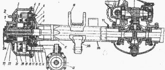
Replacing the power steering pump (power steering) Kamaz-4310, 55111, 43118 The power steering pump Kamaz-4310, 55111, 43118 must be replaced in case of the following malfunctions: - Clogged or stuck valves, as a result of which the force on the steering wheel suddenly increases or periodically changes. — Wear of pump parts, as a result of which there is a gradual increase in the force on the steering wheel at low crank speeds, as well as increased heating of the outer surfaces of the pump. — Axial movement of the Kamaz-4310, 55111, 43118 power steering pump shaft as a result of the destruction of the front bearing. — Oil leakage as a result of wear of the o-rings, cuffs and damage to the gaskets. — Mechanical damage to the pump that interferes with its normal operation. Removing the power steering pump Kamaz-4310, 55111, 43118 - Raise the cab to the first position and lock - Clean the outer surface of the pump from dirt - Drain the oil from the steering gear housing Kamaz-4310, 55111, 43118 - Disconnect the low and high pressure oil lines of the power steering drive by unscrewing the nuts and drain the remaining oil in the pump - Disconnect the low-pressure pipeline from the pump, unscrew the fastening clamp bolt and remove the low-pressure pipeline - Disconnect the high-pressure pipeline from the pump, unscrew the bolts of the two mounting clamps and remove the high-pressure pipeline - Remove three bolts attaching the pump to the flywheel housing, move the pump forward and remove it from the engine. Installation of the power steering pump KamAZ-4310, 55111, 43118 - Install the pump on the flywheel housing. Screw in the pump mounting bolts. — Install the high-pressure pipeline, connect it to the pump, screw in the bolts of the pipeline fastening clamps — Install the low-pressure pipeline, connect it to the pump, screw in the bolt of the pipeline fastening clamp — Connect the oil lines of the power steering drive KamAZ-4310, 55111, 43118, tighten the nuts — Fill oil into the steering hydraulic system and pump it. — Start the engine and check the tightness of the connections of the power steering, pump and oil cooler. Replacing the steering mechanism KamAZ-4310, 55111, 43118 The steering mechanism KamAZ-4310, 55111, 43118 must be replaced in case of the following malfunctions: — Jamming of the steering gear gear. — Increased gap in the gearing, which cannot be eliminated by adjustment. — Increased oil leakage in the steering mechanism of KamAZ-4310, 55111, 43118 due to wear or damage to the sealing rings. — Loosening the nut of the steering screw thrust bearings. — Jamming of the reaction plungers and spool in the control valve body. — Jamming or destruction of parts of the angular gearbox Kamaz-4310, 55111, 43118. — Mechanical damage to parts of the steering mechanism (cracks, holes, thread failure, etc.). Removing the steering mechanism Kamaz-4310, 55111, 43118 - Press out the ball pin of the bipod rod from the bipod eye - Unscrew the three union nuts of the heater fuel tank pipelines, disconnect the pipelines and drain the fuel from the tank and fuel lines - Unscrew the four nuts securing the heater fuel tank to the bracket and remove tank - Unbend the lock washer 4 (Fig. 1) and unscrew the nut 5 - Remove the bipod of the Kamaz-4310, 55111, 43118 steering mechanism with a puller - Unscrew the magnetic plug from the steering mechanism housing and drain the oil. Screw in the plug with a torque of 29-39 Nm (3-4 kg/cm). — Disconnect the high 8 (see Fig. 1) and low 9 pressure pipelines from the steering mechanism and drain the oil remaining in the pipelines — Unscrew the nut of the bolt securing the lower propeller shaft fork, knock out the bolt and disconnect the shaft from the steering mechanism by lifting the fork up — Unscrew the four bolt securing the steering gear housing to the front spring bracket and remove the steering gear. — Drain the remaining oil by turning the steering mechanism of KamAZ-4310, 55111, 43118 with the valve down and turning the drive gear shaft of the angular gearbox 2-3 times from one extreme position to the other.
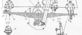
Fig.1. Steering Kamaz-4310, 55111, 43118 1— steering wheel; 2 - column; 3 — bipod thrust; 4 — lock washer; 5 - nut; 6 - bipod; 7 — steering mechanism; 8 - high pressure pipeline; 9—low pressure pipeline; 10 — cardan shaft; 11 — radiator Installation of the steering mechanism KamAZ-4310, 55111, 43118 — Install the steering mechanism KamAZ-4310, 55111, 43118 on the front bracket of the left front spring and secure it with bolts with a torque of 275-314 Nm (28-32 kg/cm). — Connect the high and low pressure pipelines to the steering mechanism — Attach the steering propeller shaft to the steering mechanism, insert the pinch bolt, tighten the nut with a torque of 13.7–16.7 Nm (1.4–1.7 kg/cm) — Install fuel tank of the heater on the bracket - Connect the three fuel lines of the heater tank - Fill the hydraulic system of the Kamaz-4310, 55111, 43118 steering drive with oil and pump it. — Install the bipod on the shaft, aligning the marks marked on the end of the shaft and on the bipod, install the lock washer, screw in the nut and tighten it with a torque of 510–539 Nm (52–55 kg/cm) — Lock the nut by bending the lock washer — Insert the ball pin bipod rod into the bipod eye, tighten the nut and pin - Check the tightness of threaded and other connections and pipelines of the power steering drive KamAZ-4310, 55111, 43118. Replacing the steering bipod rod KamAZ-4310, 55111, 43118 Steering bipod rod KamAZ-4310, 55111, 43118 must be replaced if the following malfunctions occur: — Free play. Movement in the articulated joints due to spring breakage or wear of the cotters and ball pins, the main symptom of which is increased free play of the steering wheel and unstable movement of the vehicle. — Mechanical damage to the bipod rod.
Fig.2. Bipod rod of the Kamaz-4310, 55111, 43118 steering mechanism 1 - cover; 2 — washer; 3 - spring; 4 — lower rod insert; 5 — ball pin; 6 — upper rod insert; 7 — oiler assembly; 8 - oil nipple; 9 — rod assembly; 10, 13 — protective linings; 11 — cotter pin; 12 — ball pin nut; 14 — clip Removing the steering bipod rod of KamAZ-4310, 55111, 43118 — Raise the front axle of the car and turn the steered wheels to the left until it stops — Unscrew and unscrew the nut 12 (Fig. 2) securing the ball pin of the bipod rod head on the side of the upper arm of the left steering knuckle — Unscrew and unscrew the nut securing the ball pin of the rod head on the bipod side of the Kamaz-4310, 55111, 43118 steering mechanism — Use a puller to press ball pin 5 (see Fig. 2) out of the bipod eye, disconnect the rod heads from the bipod and screw the nut onto the ball pin — Use a puller to press the ball pin out of the cone hole of the steering knuckle lever, remove the rod from the vehicle and screw the nut onto the ball pin. Installing the steering bipod rod for Kamaz-4310, 55111, 43118 — Insert the ball pin of the rear head of the Kamaz-4310, 55111, 43118 bipod rod into the cone hole in the upper arm of the steering knuckle, tighten the ball pin fastening nut with a torque of 245–314 Nm (25–32 kg/cm) and secure with a cotter pin. The rear link head of the bipod of KamAZ-4310, 55111, 43118 has a protective rubber lining 10 of a conical shape without a clip; the axis of the lubrication hole for the oiler in the rear head makes an angle of about 45° with the axis of the thrust rod - Insert the ball pin of the front head of the bipod rod into the eye of the bipod, tighten the nut securing the ball pin with a torque of 245-314 Nm (25-32 kg/cm) and secure it with a cotter pin - Lower the front axle of the vehicle Replacing the steering linkage rod KamAZ-4310, 55111, 43118 The steering linkage rod KamAZ-4310, 55111, 43118 must be replaced in case of the following malfunctions: - Free play in the articulated joints due to broken springs, wear of the crackers or ball pins, the main a sign of which is increased free play of the steering wheel and unstable movement of the car. — Bent rod and damaged threads at the ends of the rod.
Fig.3. Steering linkage rod KamAZ-4310, 55111, 43118 1, 9 - bolts; 2, 16— washers; lid; 4 - gasket; 5— spring; 6 — lower tip liner; 7 — ball pin; upper tip insert; 10 — right rod end assembly; 11 — overlay; 12 — clip; 13, 17 — nuts; 14 - cotter pin; 15 — oiler; 18 — steering linkage rod; 19 — left rod end assembly Removing the steering linkage rod KamAZ-4310, 55111, 43118 — Raise the front axle of the vehicle — Unscrew and unscrew the nut 13 (Fig. 3) securing the ball pin of the tip 10 of the steering linkage rod to the body of the right steering knuckle — Press it out with a puller ball pin 7 (see Fig. 3) of the rod from the conical hole of the right steering knuckle, disconnect the rod tip from the knuckle and screw the nut onto the ball pin - Make transitions for the left rod end of the Kamaz-4310, 55111, 43118 steering linkage and remove the rod
Fig.4. Mounting size of the steering linkage KamAZ-4310, 55111, 43118 Installation of the steering linkage linkage KamAZ-4310, 55111, 43118 - Check and, if necessary, install the mounting size of the steering linkage linkage. To set the mounting size of the steering linkage rod Kamaz-4310, 55111, 43118, loosen the fastening of the tips on the left and right threaded ends of the rod by unscrewing the nuts 17 bolts 9, and unscrew or screw in the tips until the required length of the rod is obtained. The rod length (Fig. 4) (distance between the centers of the tips) should be 1480 mm. The tips must be wrapped to the same length (the difference is no more than 3 mm). In one revolution, the left rod tip moves along the axis by 2 mm, and the right tip - by 1.5 mm - Insert the ball pin of the right rod tip of the Kamaz-4310, 55111, 43118 steering linkage into the conical hole of the right steering knuckle, tighten the nut. — Make the transition for the left tie rod end without tightening the ball pin fastening nut — Lower the front axle of the car, remove the stands Check and, if necessary, adjust the wheel toe in the following order: — check the pressure in the tires of the front wheels, which should be 294 kPa (3 kgf/cm2). If necessary, bring it to normal; — set the front wheels to a position corresponding to the vehicle moving in a straight line; — measure the distance between the side flanges of the wheel rims at the rear at the height of the wheel centers, mark the measurement points with chalk; — roll the Kamaz-4310, 55111, 43118 forward by half a turn of the front wheels; — measure the distance between the side flanges of the front wheel rims at the same points as before, at the height of the wheel centers. The difference in the results of measuring the distances between the side flanges of the wheel rims before and after rolling the car determines the amount of wheel toe. Adjust the toe-in of the wheels by changing the rod length of KamAZ-4310, 55111, 43118 in the following order: - make transitions for the right rod tip, then, screwing the tip onto the rod with large toe-in and unscrewing with small toe-in, ensure normal toe-in of the front wheels. If it is not possible to adjust the toe-in by rotating the right end of KamAZ-4310, 55111, 43118, then make the transition for the right end of the rod. Then, by rotating the left tip, establish normal toe-in - Tighten the nuts securing the pins with a torque of 245-314 Nm (25-32 kg/cm) and secure - Tighten the nuts of the bolts securing the pins on the rod with a torque of 53.9-58.8 Nm (5 .5—6.0 kg/cm) Replacing the crosspiece of the Kamaz-4310, 55111, 43118 steering propeller shaft The Kamaz-4310, 55111, 43118 steering driveshaft crosspieces must be replaced in case of wear of the needle bearings, o-rings, spikes of the crosspiece, causing increased free play of the steering wheel or increased force on it when the pump and power steering are in good working order. Removing the crosspiece of the Kamaz-4310, 55111, 43118 steering drive shaft - Unscrew the screws of the cover 10 (Fig. 5) of the steering column mounting flange 13 and remove the cover - Unscrew the nut of the coupling bolt of the upper fork of the Kamaz-4310, 55111, 43118 steering drive shaft and knock out the bolt - Lift and fix the front facing panel of the cab - Unscrew the nut of the coupling bolt of the lower fork of the steering propeller shaft and knock out the bolt - Disconnect the upper fork of the steering propeller shaft Kamaz-4310, 55111, 43118 from the splined end of the steering column shaft - Disconnect the lower fork of the propeller shaft steering shaft from the splined end of the drive bevel gear shaft of the angular gearbox of the power steering - Remove the steering driveshaft, moving it down and forward - Remove the joint crosspieces Installation of the steering driveshaft crosspieces Kamaz-4310, 55111, 43118 - Assemble the driveshaft joints. The forks of the propeller shaft of the steering wheel KamAZ-4310, 55111, 43118 after its assembly must be in the same plane, - The holes for the coupling bolts of the upper and lower forks must be located relative to the longitudinal axis of the shaft in different directions - Install the shaft in place, moving it up and back . Install the steering driveshaft onto the vehicle, pointing upward with the splined bushing fork. — Connect the lower fork of the propeller shaft of the steering wheel Kamaz-4310, 55111, 43118 with the splined end of the shaft of the drive bevel gear of the angular gearbox of the hydraulic booster, aligning the hole for the fork coupling bolt with the groove on the hydraulic booster shaft — Make a transition for the upper fork of the propeller shaft — Install and secure the coupling bolts of the Kamaz-4310, 55111, 43118 steering propeller shaft forks with nuts with a torque of 13.7-16.7 Nm (1.4-1.7 kg/cm) - Install and secure the steering column mounting flange cover - Lower and secure the front facing Cabin panel Fig.5. Installation of the steering column Kamaz-4310, 55111, 43118 1 - steering wheel - 2 - upper cover, 3 - nut; 4 — bottom cover: 6 — screw; 6, 8, 12, 14, 15 — bolts with washers; 7 — column assembly; 9 — screw with washer; 10 - flange cover; 11 - gasket; 13 — column mounting flange; 16—column mounting bracket Replacing the steering column Kamaz-4310, 55111, 43118 The steering column Kamaz-4310, 55111, 43118 must be replaced if the following malfunctions occur: — Increased wear or destruction of the ball bearings of the column shaft. — Axial movement of the steering column shaft KamAZ-4310, 55111, 43118. — Bent steering column shaft, — Wear of the splines at the ends of the shaft. — Deformation and damage to the column pipe, impairing the normal operation of the column. Removing the steering column Kamaz-4310, 55111, 43118 - Set the front wheels of the car to a position corresponding to driving straight - Turn off the car battery switch - Remove the decorative cover 2 (see Fig. 5) of the steering wheel 1 - Unscrew the nut 3 securing the steering wheel to column shaft 7 - Remove the steering wheel from the steering column shaft Kamaz-4310, 55111, 43118 - Unscrew the fastening screws and remove the combination switch from the column, disconnecting the plug connectors of the switch's electrical wires - Unscrew the screws 9 of the cover 10 of the flange 13 of the column fastening and remove the cover 10 c gasket 11 - Unscrew the nut of the coupling bolt of the upper fork of the steering propeller shaft, knock out the bolt and disconnect the fork from the column shaft - Unscrew the bolts 8 securing the column to the flange 13 - Unscrew the bolts 6 securing the steering column to bracket 16 and remove the column Installing the Kamaz-4310 steering column . 4-1.7 kg/cm). The pinch bolt is installed when the hole for it in the fork coincides with the groove on the steering column shaft of KamAZ-4310, 55111, 43118 - Install the flange cover 10 with a gasket and secure with screws 9 with washers - Secure the steering column of KamAZ-4310, 55111, 43118 on bracket 16 6 bolts with spring washers. When attaching the steering column to bracket 16, skew of the column is not allowed - Install the combination switch on the column and secure it with screws. Connect the plug connectors of the electrical wires of the switch - Install the steering wheel on the column shaft. When the position of the steered wheels corresponds to the vehicle moving in a straight line, the steering wheel spokes should be positioned symmetrically relative to the vertical plane passing through the column axis and parallel to the longitudinal axis of the car - Screw the steering wheel mounting nut onto the column shaft with a torque of 60-80 Nm (6-8 kg/cm) — Install the decorative steering wheel cover
_______________________________________________________________________________
_______________________________________________________________________________
_______________________________________________________________________________
- Clutch KamAZ-5320 and its components
- Repair of PGU and Kamaz clutch master cylinder
- Gearbox gearbox KamAZ 141
- Gearbox gearbox KamAZ ZF 16
- Gearbox 152 Kamaz with divider
- Gearbox gearbox 154 Kamaz
- Gearbox Kamaz-4308
- Clutch of a Kamaz-4308 car
- Clutch and gearbox KamAZ-65115
- Disassembly and assembly of Kamaz-4310, 55111, 43118 gearboxes
_______________________________________________________________________________
- Cylinder block, head and valves Kamaz-740
- Fuel system of Kamaz-740 diesel engine
- Adjustments and repairs of fuel injection pump Kamaz-740
- Drive axles of the Kamaz-4310 vehicle
- Repair of Kamaz drive axle gearbox
- Rear axle KamAZ-4308
- Axles and suspensions of Kamaz-65115 dump trucks
- Installation of Kamaz cardan shafts and axles
- Repair of Kamaz vehicle transfer case
- Kamaz power steering - adjustments and repairs
- Repair of Kamaz steering gear parts
- Steering parts Kamaz-4308
- Parts of the brake system Kamaz-4308
- Brake system and brake drive Kamaz
- Repair of brake valves and Kamaz compressor
- Suspension Kamaz-4310, 55111, 43118 and their parts
- Frame and suspension of the Kamaz-4308 car
- Cabin details and platform KamAZ-65115
- Cabin components Kamaz-4308
- Platform mechanism of Kamaz vehicles
- Klintsy KS 65719-5K truck crane based on KamAZ-6522 chassis
- Truck crane KC-35719-7-02 based on Kamaz-43118 chassis
- Truck crane Galichanin KC-55713-1K based on KamAZ-65115 6x4
- Ivanovets KS-45717K-1/1R truck crane based on KamAZ-65115 chassis
- Ivanovets KS-3577-3/4 truck crane on KamAZ-43253 4x2 chassis
Causes of malfunction
The steering mechanism is a reliable unit that is difficult to malfunction after driving less than 150 - 200 thousand kilometers, but it is possible. This is due to improper operation of the car, but there are also other reasons:
- Breakage of mechanism parts due to wear;
- Poor condition of roads;
- Poor quality oils and other automotive fluids;
- Lack of periodic technical inspection.
Often the problem lies in a malfunction of the steering rack with regards to the steering shaft on which the gear is attached. To overhaul it, the service carries out diagnostics. Then, if necessary, use a special new repair kit, which includes bushings, bearings, rubber rings, seals and other spare parts. At the request of the client, the craftsmen are ready to replace the damaged part with a new contract steering rack, which will fundamentally solve the problem.
Power steering device KAMAZ 4310
KAMAZ-4310 was developed as a passable army vehicle for the army with a 6x6 wheel arrangement, which brought its own changes to the design of the power steering
in terms of its increased ability and resistance to stress.
The power cylinder is made in a single crankcase with the entire steering mechanism. The control valves are equipped with a system of reaction plungers and centering springs to create reaction force on the steering wheel when turning it at high speeds.
Another design feature is the mounting of the steering bipod. On all-wheel drive KAMAZ vehicles of the 4310 family, bolts and cotter pins were replaced with nuts with lock washers.
Power steering device KAMAZ 4310
- 853354 — Bolt M8-6gх30
- 1/05166/73 — Spring washer 8
- 4310-3401079 — Front cover
- 864201 — O-ring
- 853512 — Nut M25x1.5-6N
- 5320-3401373 — Spring washer
- 1/21647/21 — Nut M10x1.25-6N
- 1/05168/73 — Spring washer 10
- 864650 — Thrust bearing
- 4310-3400020 — Steering mechanism assembly
- 4310-3401770 — Angular gearbox assembly (45342401841)
- 4310-3401090 — Steering bipod
- 853631 — Washer
- 853567 — Nut
- 864707 — Blank ball
- 1/13069/21 — Bolt M10x1.25-6gx30
- 1/05168/73 — Spring washer 10
- 251648 — Nut M14x1.5-6N OST 37.001.197-75
- 4310-3401083 — Side cover
- 4310-3401029 — Sealing cuff
- 864206 — O-ring
- 864203 — O-ring for steering gearbox
- 5320-3401791 — Bushing
- 864204 — O-ring
- 862803 — Thrust ring
- 5320-3401140 — Adjusting washer
- 5320-3401141 — Adjusting washer (453471205)
- 5320-3401142 — Adjusting washer
- 5320-3401144 — Washer
- 5320-3401163 — Adjustment screw
- 5320-3401176 — Thrust washer
- 4310-3401065 — Bipod shaft
- 4310-3401029-10 — Bipod shaft sealing collar
- 4310-3401789 — Thrust washer for bipod shaft sealing collar
- 4310-3401015 — Steering mechanism housing
- 864207 — O-ring for steering mechanism
- 5320-3401371 — Bypass valve
- 5320-3401377 — Valve cap
- 4310-3401529 — Rear steering housing cover
- 1/05168/73 — Spring washer
- 1/13069/21 — Bolt M10x1.25-6gx30
- 4310-3401076 — Crankcase bushing
- 864190 — Bipod shaft cuff assembly
- 864194 — Thrust ring
- 4310-3401030 — Outer cuff for shaft seal assembly
- 864707 — Blank ball
- 2101-2401046 — Magnetic plug assembly
- 4310-3401417 — Set screw
- 4310-3401411 — Rack-piston
- 5320-3401038 — Ball nut
- 864707 — Blank ball
- 5320-3401179 — Ball nut groove
- 4310-3401415 — O-ring for rack-piston
- 864208 — Spacer ring
- 1/35466/21 — Hairpin M10x1.25x20x35
- 1/05168/73 — Spring washer 10
- 1/21647/21 — Nut M10x1.25-6N
- 862812 — Bushing thrust ring
- 5320-3401361 — O-ring for steering screw
- 5320-3401391 — Spacer ring
- 5320-3401403 — Floating bushing
- 4310-3401359 — Steering screw
- 1/05166/73 — Spring washer 8
- 1/13438/31 — Bolt M10x1.25-6gx50
- 379432 — Seal
- 258266 — Wire
- 4310-3401780 — Safety valve adjusting screw cap
- 1/05168/73 — Spring washer 10
- 853034 — Bolt M10x1.5-6gx65
Power steering pump KAMAZ-4310
The hydraulic pump creates pressure of the working fluid in the power steering. It is usually located on the camber of the cylinder block. KAMAZ trucks mainly use vane-type, double-acting pumps. During one revolution of the impeller, both a discharge cycle and a suction cycle occur.
Typical malfunctions of power steering KAMAZ-4310
Faults are divided into 2 types: mechanical faults and hydraulic faults.
When operating in the far north, the viscosity of the working fluid increases, which in turn leads to it tearing off the system seals.
Constant drop in oil level in the pump reservoir.
• The reason is damage to the pump shaft seal.
Remedy: To solve, you need to replace the oil seal. Oil releases through the safety valve of the pump reservoir cap.
• Excessive ATF in the system. Remedy: Drain off excess liquid.
• Dirty or faulty pump filter. Remedy: Replace the filter.
• Violation of the reservoir geometry. Remedy: If the violation is minor, then align the collector. If the violations are serious, then it is better to replace the collector.
• The seal of the manifold gasket is broken, air has entered the system.
Remedy: Remove air from the system and then replace the gaskets. Increased noise during pump operation.
• There is not enough ATF in the system. Remedy: Add fluid.
• The pump filter does not perform its functions. Remedy: Replace the filter.
• There is air in the system. . Remedy: Remove air and restore seal.
• Collector deformation. Remedy: If the violation is minor, align the collector. If the violations are serious, then it is better to replace the collector.
• The seal of the computer gasket is broken.
Remedy: Replace the gasket. Knock in the steering mechanism.
• Increased clogging of the steering gear clutch. Remedy: Adjust the blockage using the adjusting screw.
• Loosening the nuts of the steering gear joint bolts. Remedy: Tighten the nuts.
• The nut of the wedges securing the propeller shaft forks is loose or there is increased wear of the spline joint.
Remedy: Tighten the nuts and replace the spline joints. The steering mechanism jams during operation
• The valve spools or jet plungers are jammed. Remedy: Disassemble the power steering, thoroughly clean and wash in solvent.
• Increased wear of the steering gear.
Remedy: The entire steering mechanism needs to be replaced. Complete lack of gain at different engine speeds
• The pump safety valve seat has become loose. Remedy: Tighten the seat.
• The valve spring has burst. Remedy: Disassemble the valve and replace the spring.
• The bypass valve has stopped working. Remedy: Disassemble the pump and clean or replace the valve.
• The steering check valve has stopped working. Remedy: Disassemble the pump and clean or replace the valve.
• The steering gear safety valve spring has broken.
Remedy: Replace the spring. Insufficient, uneven operation of the hydraulic booster.
• The steering gear is overtightened. Remedy: Adjust the steering force using the adjusting screw.
• The pump does not develop the required pressure in the system. Remedy: Clean the pump and replace it if it is very worn.
• Loss of working fluid. Remedy: Replace rubber seals and add fluid.
• Steering gear check valve leaking. Remedy: Eliminate the leak and restore the valve's tightness.
• Insufficient amount of liquid in the system, presence of air in it. Remedy: Add working fluid and remove air from the power steering.
Spare parts for KAMAZ-4310 KamAZ-5490 gearbox ZF gearbox Transfer cases Gearboxes
Buy spare parts from us:
| We complete applications of any complexity, competitive prices, and a system of volume discounts. |
| We provide a clear guarantee of the quality of spare parts from manufacturers |
| Prompt delivery throughout Russia |
| Call or write to [email protected] Information will be required: car model, year of manufacture, unit model, Euro class. |
Types of steering
In total, there are 3 types of steering depending on the gearbox: screw
,
worm
and
rack
. The most popular and frequently performed is the rack and pinion one, which is designed for passenger cars. It has a simple design, making it sensitive to any serious impact. The worm type has good resistance to any impacts, but differs greatly in price. The screw mechanism is practically no different from the worm mechanism, but has a higher efficiency.
Poor-quality DIY steering repair can lead to complete loss of control while driving, which promises additional problems and more expensive repairs.
Maintenance and repair of KAMAZ 5320 steering. Equipment and tools. Organization of the workplace.
Content.
1. Introduction………………………………………………………..……………………..…………1
2. Maintenance and repair of the KAMAZ 5320 steering system. Equipment and tools. Organization of the workplace.…………………………………………2
3. Safety precautions…………………………………………………………..…………….5
4. Conclusion…………………………………………………………………………………..…………….6
5. List of references…………………………………………….…………….7
6. Notes…………………………………………………………………………………………………………….8
| Change |
| Sheet |
| Document no. |
| Signature |
| date |
| Sheet |
| Change |
| Sheet |
| Document no. |
| Signature |
| date |
| Sheet |
| Developed |
| Check |
| Review. |
| N. Cont. |
| Approved |
| Introduction VAZ 2109 bots |
| Lit. |
| Sheets |
| ATTgr-AV-43/44 |
1.Introduction
Steering is used to change and maintain the selected direction of movement of the vehicle. The main way to change the direction of movement is to turn the front guide wheels in a horizontal plane relative to the rear wheels.
The KamAZ-5320 vehicle uses mechanical steering with a hydraulic booster. The steering mechanism with an angular gear reducer is equipped with a steering gear with working pairs of the type screw - nut with circulating balls and rack - gear sector. The steering gear ratio is 20:1.
The hydraulic booster makes driving easier and increases safety. Hydraulic booster, using engine energy to turn and hold the wheels, reduces driver fatigue, improves the vehicle's maneuverability and ensures control in difficult conditions, such as sudden tire damage.
Maintenance and repair of KAMAZ 5320 steering. Equipment and tools. Organization of the workplace.
THAT:
Car maintenance is divided into the following types:
-EO:
— designed to monitor the condition of the steering drive.
-TO-1:
– include checking the oil level in the power steering pump reservoir; if necessary, add oil to the specified level;
- Lubricate the steering rod joints using a grease nipple until fresh grease appears in the gaps.
-TO-2:
– checking the clearances in the steering rod joints and driveshaft;
– check and, if necessary, restore the free play of the steering wheel within acceptable limits;
– remove and wash the pump filter.
| Change |
| Sheet |
| Document no. |
| Signature |
| date |
| Sheet |
Removing the steering mechanism.
— Press the bipod rod ball pin out of the bipod eye.
— Unscrew the three union nuts of the heater fuel tank pipelines, disconnect the pipelines and drain the fuel from the tank and fuel lines.
— Unscrew the four nuts securing the heater fuel tank to the bracket and remove the tank.
— Unbend lock washer 4 (Fig. 1) and unscrew nut 5.
— Remove the bipod of the KamAZ-5320 steering mechanism with a puller.
— Remove the magnetic plug from the steering gear housing and drain the oil. Screw in the plug with a torque of 29-39 Nm (3-4 kg/cm).
— Disconnect the high 8 (see Fig. 1) and low 9 pressure pipelines from the steering mechanism and drain the remaining oil in the pipelines.
— Unscrew the nut of the bolt securing the lower propeller shaft fork, knock out the bolt and disconnect the shaft from the steering mechanism by lifting the fork up.
— Remove the four bolts securing the steering gear housing to the front spring bracket and remove the steering gear.
— Drain the remaining oil by turning the steering mechanism of the KamAZ-5320 with the valve down and turning the shaft of the drive gear of the angular gearbox 2-3 times from one extreme position to the other.
| Change |
| Sheet |
| Document no. |
| Signature |
| date |
| Sheet |
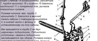
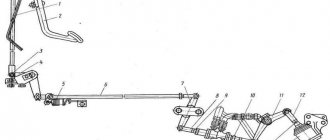
Rice. 1. Steering control of the KamAZ-5320 car:
1 — steering wheel; 2 — steering column; 3 - clamp; 4 - flange; S—adjusting nut; 6 — cardan transmission; 7—radiator; 8 — control valve; 9 — angular gearbox; 10 — steering mechanism; 11 — longitudinal steering rod; 12 — bipod; 13 — bipod shaft; 14 - pump; 15 - tank
| Change |
| Sheet |
| Document no. |
| Signature |
| date |
| Sheet |
.
Content.
1. Introduction………………………………………………………..……………………..…………1
2. Maintenance and repair of the KAMAZ 5320 steering system. Equipment and tools. Organization of the workplace.…………………………………………2
3. Safety precautions…………………………………………………………..…………….5
4. Conclusion…………………………………………………………………………………..…………….6
5. List of references…………………………………………….…………….7
6. Notes…………………………………………………………………………………………………………….8
| Change |
| Sheet |
| Document no. |
| Signature |
| date |
| Sheet |
| Change |
| Sheet |
| Document no. |
| Signature |
| date |
| Sheet |
| Developed |
| Check |
| Review. |
| N. Cont. |
| Approved |
| Introduction VAZ 2109 bots |
| Lit. |
| Sheets |
| ATTgr-AV-43/44 |
1.Introduction
Steering is used to change and maintain the selected direction of movement of the vehicle. The main way to change the direction of movement is to turn the front guide wheels in a horizontal plane relative to the rear wheels.
The KamAZ-5320 vehicle uses mechanical steering with a hydraulic booster. The steering mechanism with an angular gear reducer is equipped with a steering gear with working pairs of the type screw - nut with circulating balls and rack - gear sector. The steering gear ratio is 20:1.
The hydraulic booster makes driving easier and increases safety. Hydraulic booster, using engine energy to turn and hold the wheels, reduces driver fatigue, improves the vehicle's maneuverability and ensures control in difficult conditions, such as sudden tire damage.
Maintenance and repair of KAMAZ 5320 steering. Equipment and tools. Organization of the workplace.
THAT:
Car maintenance is divided into the following types:
-EO:
— designed to monitor the condition of the steering drive.
-TO-1:
– include checking the oil level in the power steering pump reservoir; if necessary, add oil to the specified level;
- Lubricate the steering rod joints using a grease nipple until fresh grease appears in the gaps.
-TO-2:
– checking the clearances in the steering rod joints and driveshaft;
– check and, if necessary, restore the free play of the steering wheel within acceptable limits;
– remove and wash the pump filter.
| Change |
| Sheet |
| Document no. |
| Signature |
| date |
| Sheet |
Removing the steering mechanism.
— Press the bipod rod ball pin out of the bipod eye.
— Unscrew the three union nuts of the heater fuel tank pipelines, disconnect the pipelines and drain the fuel from the tank and fuel lines.
— Unscrew the four nuts securing the heater fuel tank to the bracket and remove the tank.
— Unbend lock washer 4 (Fig. 1) and unscrew nut 5.
— Remove the bipod of the KamAZ-5320 steering mechanism with a puller.
— Remove the magnetic plug from the steering gear housing and drain the oil. Screw in the plug with a torque of 29-39 Nm (3-4 kg/cm).
— Disconnect the high 8 (see Fig. 1) and low 9 pressure pipelines from the steering mechanism and drain the remaining oil in the pipelines.
— Unscrew the nut of the bolt securing the lower propeller shaft fork, knock out the bolt and disconnect the shaft from the steering mechanism by lifting the fork up.
— Remove the four bolts securing the steering gear housing to the front spring bracket and remove the steering gear.
— Drain the remaining oil by turning the steering mechanism of the KamAZ-5320 with the valve down and turning the shaft of the drive gear of the angular gearbox 2-3 times from one extreme position to the other.
| Change |
| Sheet |
| Document no. |
| Signature |
| date |
| Sheet |
Rice. 1. Steering control of the KamAZ-5320 car:
1 — steering wheel; 2 — steering column; 3 - clamp; 4 - flange; S—adjusting nut; 6 — cardan transmission; 7—radiator; 8 — control valve; 9 — angular gearbox; 10 — steering mechanism; 11 — longitudinal steering rod; 12 — bipod; 13 — bipod shaft; 14 - pump; 15 - tank
| Change |
| Sheet |
| Document no. |
| Signature |
| date |
| Sheet |
.