Repair manual for tractors from the Minsk plant. The nuances of repair work
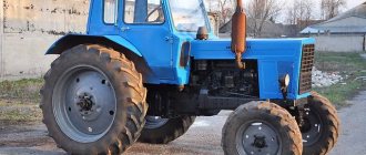
MTZ tractors are the best examples of agricultural machinery available on the domestic market. They are not only reliable, multifunctional, unpretentious in care and maintenance, but also quite economical, which is especially important in modern conditions. But no matter how fail-safe the equipment is, as it is used, natural wear and tear occurs on its individual components and assemblies. In this situation, there is only one solution - repair of MTZ tractors, the specifics of which we will talk about.
Repair of tractor engine MTZ-80, MTZ-82
The diesel engine assembly (Fig. 2.1.6) is removed from the tractor for repair or replacement if cracks are detected in the cylinder block, suspicious knocking of the main or connecting rod bearings, or a maximum gap in at least one of the crankshaft journal-liner interfaces.
What type of MTZ engine repair to perform (major or current) is decided by measuring the main parameters: piston pins, pistons, cylinder liners, connecting rod bearings.
First, check the condition of the connecting rod bearings and crankshaft journals.
For this purpose, remove the oil pan, oil lines, oil pump (Fig. 2.1.7), connecting rod caps, and measure the diameter of the crankshaft connecting rod journals (see Fig. 2.1.8).
Rice. 2.1.6. MTZ-80, MTZ-82 tractor engine assembly: 1— oil pan; 2 - crankshaft; 3 — connecting rod; 4 - flywheel; 5 - camshaft; 6 — cylinder block; 7 — cylinder head; 8 — cylinder head cover; 9 — cap; 10 - valve; 11 — valve spring; 12 - piston; 13 — rod; 14 - fan
The diameter of the connecting rod journals MTZ-80, MTZ-82 must be measured in two planes - parallel and perpendicular to the longitudinal axis of the connecting rod.
If the ovality of the journals exceeds the permissible value or if their diameter becomes less than the lower tolerance of the corresponding size group, the crankshaft must be removed (Fig. 2.1.9, 2.1.10) and sent for regrinding to the next repair size.
| Rice. 2.1.7. How to remove the oil pump MTZ-80, MTZ-82: 1 - discharge pipeline; 2 - oil pump | Rice. 2.1.8. How to measure the diameter of the connecting rod journals of the crankshaft MTZ-80, MTZ-82: 1 - micrometer; 2 - crankshaft connecting rod journal |
| Rice. 2.1.9. How to remove the crankshaft MTZ-80, MTZ-82 | Rice. 2.1.10. How to remove the rear crankshaft support MTZ-80, MTZ-82 1 - rear support; 2 - rear support mounting bolts |
Nominal and repair dimensions of the crankpins of the D-240 engine crankshaft
| Designation of size group | Size size, mm |
| H1 | 68,16—68,17 |
| H2 | 67,91—67,92 |
| D1 | 67,66—67,67 |
| P1 | 67,41—67,42 |
| D 2 | 67,16—67,17 |
| P2 | 66,91—66,92 |
| DZ | 66,66—66,67 |
| RZ | 66,41—66,42 |
In fact, in addition to the repair dimensions (P1, P2, P3), alternating every 0.5 mm and installed by the engine manufacturer, in case of minor wear, the crankshaft journals are sharpened to additional dimensions (D1, D2, DZ), replaced with repair dimensions every 0 .25 mm. Inserts of repair sizes for additional sizes (D1, D2, DZ) are processed in approximately the same way. The ovality of the connecting rod journals of the D-240 engine should be no more than 0.06 mm.
If, after measuring the connecting rod journals, it turns out that all dimensions are within normal limits, disassembling the engine continues (Fig. 2.1.11—2.1.14) by removing the cylinder head and removing the pistons and connecting rods assemblies.
To determine whether it is worth changing the connecting rod bearing shells, measure the diameter of the connecting rod bearing hole with its cap assembled with the shells tightened (Fig. 2.1.15).
| Rice. 2.1.11. How to remove the cap of the cylinder head cover MTZ-80, MTZ-82 |
| Rice. 2.1.12. How to remove the cylinder head cover MTZ-80, MTZ-82 |
| Rice. 2.1.13. How to remove the rocker shaft assembly and disconnect the MTZ-80, MTZ-82 pipelines |
| Rice. 2.1.14. How to remove the cylinder head MTZ-80, MTZ-82 |
| Rice. 2.1.15. How to measure the diameter of the connecting rod bearing hole MTZ-80, MTZ-82: 1 - indicator bore gauge; 2 — connecting rod assembly with liners |
The difference in the measurements of the diameters of the crankshaft connecting rod journal and the connecting rod bearing bore shows the actual diametrical clearance in the connecting rod bearing. The calculated clearance in the connecting rod bearings is in the range of 0.05-0.12 mm, the permissible clearance should not exceed 0.3 mm.
If the surface of the liners is in satisfactory condition, an important reason for replacement may be the size of the diametrical clearance in the bearing. When inspecting the condition of the liners, it should be remembered that the surface of the antifriction layer is considered acceptable if there are no scuffs on it, there are no changes in the antifriction material and there are no foreign inclusions
When inspecting the condition of the liners, it should be remembered that the surface of the antifriction layer is considered acceptable if there are no scuffs on it, there are no changes in the antifriction material and there are no foreign inclusions.
Next is the cylinder head MTZ-80, MTZ-82.
Recommendations for routine repairs of MTZ-80, MTZ-82 tractors
Belarus tractor diesel repair
The complete diesel engine (Fig. 2.1.6) is removed from the tractor and replaced with a new one or repaired in case of cracks in the cylinder block, emergency knocking of the main or connecting rod bearings, the maximum value of the gap, and in at least one crankshaft journal-liner interface.
Rice. 2.1.6. Diesel assembly: 1— oil pan; 2 - crankshaft; 3 — connecting rod; 4 - flywheel; 5 - camshaft; 6 — cylinder block; 7 — cylinder head; 8 — cylinder head cover; 9 — cap; 10 - valve; 11 — valve spring; 12 - piston; 13 — rod; 14 - fan
The type of repair - major or current - is determined by measuring the main parts of a diesel engine: piston pins, pistons, cylinder liners, connecting rod bearings.
First of all, check the condition of the connecting rod bearings and crankshaft journals.
To do this, remove the oil pan, oil lines, oil pump (Fig. 2.1.7), connecting rod caps, and measure the diameter of the crankshaft connecting rod journals (Fig. 2.1.8).
The diameter of the connecting rod journals is measured in two planes - parallel and perpendicular to the longitudinal axis of the connecting rod.
If the ovality of the journals exceeds the permissible size or their diameter is less than the lower tolerance of the corresponding size group, then the crankshaft must be removed (Fig. 2.1.9, 2.1.10) and ground to the next repair size.
| Rice. 2.1.7. Removing the oil pump: 1 - discharge pipe; 2 - oil pump |
| Rice. 2.1.8. Measuring the diameter of the crankpins of the crankshaft: 1 - micrometer; 2 - crankshaft connecting rod journal |
| Rice. 2.1.9. Removing the crankshaft |
| Rice. 2.1.10. Removing the rear support of the crankshaft: 1 - rear support; 2 - rear support mounting bolts |
Nominal and repair dimensions of the connecting rod journals of the crankshaft of the D-240 diesel engine
| Designation of size group | Size size, mm |
| H1 | 68,16—68,17 |
| H2 | 67,91—67,92 |
| D1 | 67,66—67,67 |
| P1 | 67,41—67,42 |
| D 2 | 67,16—67,17 |
| P2 | 66,91—66,92 |
| DZ | 66,66—66,67 |
| RZ | 66,41—66,42 |
In practice, in addition to the repair dimensions (P1, P2, P3), alternating through 0.5 mm and determined by the diesel manufacturer, in case of minor wear, the crankshaft journals are ground to additional dimensions (D1, D2, DZ), alternating with the repair dimensions through 0.25 mm. In the same way, inserts of repair sizes are bored to additional sizes (D1, D2, DZ). The ovality of the connecting rod journals of the D-240 diesel engine is allowed no more than 0.06 mm.
If the dimensions of the connecting rod journals are within normal limits, (disassembly of the diesel engine continues (Fig. 2.1.11—2.1.14) remove the cylinder head and remove the pistons and connecting rods assemblies.
To decide whether it is necessary to replace the connecting rod bearing shells, measure the diameter of the connecting rod bearing hole with its cap assembled with the shells tightened (Fig. 2.1.15).
| Rice. 2.1.11. Removing the cylinder head cover |
| Rice. 2.1.12. Removing the cylinder head cover |
| Rice. 2.1.13. Removing the rocker shaft assembly and disconnecting the pipelines |
| Rice. 2.1.14. Removing the cylinder head |
| Rice. 2.1.15. Measuring the diameter of the connecting rod bearing hole: 1 - indicator bore gauge; 2 — connecting rod assembly with liners |
The difference in the diameter measurements of the crankshaft connecting rod journal and the connecting rod bearing bore gives the actual diametrical clearance in the connecting rod bearing. The nominal clearance in connecting rod bearings corresponds to 0.05-0.12 mm, the permissible clearance is no more than 0.3 mm.
In cases where the surface of the liners is in satisfactory condition, the only criterion for the need to replace them is the size of the diametrical clearance in the bearing. When assessing the condition of the liners by inspection, it should be borne in mind that the surface of the antifriction layer is considered satisfactory if there are no scuffs, chipping of the antifriction material, or inclusions of foreign materials.
Field repair
However, transportation to repair shops is not always required. Quite often, a tractor breakdown is quite minor, and its correction is quite possible in the field. As practice shows, field repairs most often concern the following: replacing gaskets on the head block, replacing injectors or adjusting them, adjusting the mechanisms responsible for the operation of the gas distribution in the engine, replacing valves with their subsequent grinding in, installing new rubber rings and seals. In addition, the fuel pump and cylinder head, faulty temperature sensors, hydraulic hoses, distributor and pump of the tractor hydraulic complex, as well as much else that does not require serious intervention in the mechanisms, can be quickly replaced.
Malfunctions and repair gaps
The main list of malfunctions leading to stopping the operation of the tractor and subsequent disassembly and repair of mechanisms at intervals:
- Sometimes clutch linings slip when the main oil seal on the input shaft wears out. Oil flows between the flywheel and the driven movable disk.
- There is no braking of the gearbox input shaft. Shifting gears is difficult or makes a grinding noise. Adjust or replace the clutch brake.
- Spontaneous shutdown of the independent PTO rotation speed
- Transmission oil leaks from the housing at intervals.
The overall operation of the unit depends on the condition of the support bearings of the drive power and driven PTO shafts. Due to the increase in play in the supports, the gaps in the engagement of gear blocks of the gearbox and splined joints increase, which leads to increased wear of parts, the appearance of a hum, beating during operation, and spontaneous knocking out of the PTO speed position.
To replace support bearings, shafts and gears in between, complete dismantling of the unit is required, followed by disassembly and replacement of worn parts.
Replacing oil seals in between
To replace the oil seals on the shaft supports in the front partition of the housing, the gaps on the power shaft, the driven PTO shaft and the hydraulic system pump drive axis, the following steps must be performed:
- We remove the hood.
- Disconnect the transfer case driveshaft.
- Unscrew the nuts securing the unit with the motor.
- Using the front wheels, we roll the engine away from the gap.
- Remove the lifting mechanism with the bracket.
- We change the seals.
- We collect cuttings.
- We roll up the tractor.
- We fasten the gap.
- Install the hood.
In the upper front support of the pump drive axis, the rubber sealing ring is replaced. The fixing bolt is unscrewed from the axle. Then remove the bushing and replace the o-ring. If the bushing and seat are broken, grind a new one of a larger size.
In the middle front support between the power shaft and the PTO drive shaft, the oil seal is replaced, clamped by a sleeve and a bushing.
The lower support is sealed with an oil seal and closed with a cup-shaped cover with four bolts.
The tightness of the seals between the dry clutch compartment and the lubricated part of the gap ensures the tightness of the general lubrication system of the tractor transmission and isolates the clutch friction discs from oil, which causes slipping.
Repair of the drive and speed change gear of the independent PTO
Malfunctions of the unit include knocking out the on position of the PTO rotation speed. One of the reasons is a malfunction of the spring-ball retainer of the fork on the shift axis installed in the lower housing cover.
- Remove the cover with the switching drive
- Disconnect the shift fork and axle, gaining access to the spring-ball retainer
- Inspect or replace parts of the retainer
- Reassemble the axle and fork in reverse order
Clutch brake repair
The working mechanism of the brake consists of movable and fixed disks and a rod system connected to the pedal. The surface of the discs is protected by friction linings, which, when compressed, stop the clutch and the input shaft of the unit.
The main malfunctions of the device arise in the event of incorrect adjustment of the levers or premature wear of the ring linings. The recommended thickness of the friction plates is 5 mm, the amount of wear is no more than 3 mm. Work to restore the brake is carried out simultaneously with changing the oil seal.
To get to the mechanism disks, in addition to the work listed above, you need to remove the lift bracket and the middle top cover on the housing. The factory-made linings are connected to the surface of the disc using special glue. The repair procedure in this case consists of replacing the fixed and mobile disks with new assembled products.
Correction of the rod length is carried out using a threaded coupling located on the rod of the device. Just below there is a working spring, the size of which must also be adjusted (≤ 35 mm).
The technical condition of the gap mechanisms affects the operation of the entire tractor transmission. In the event of problems during the operation of the tractor gearbox and difficulty engaging gears, the reasons should first be sought in the mechanisms of the described unit.
Sequence of repair work
As a rule, experienced machine operators are able to assess the technical condition of the MTZ-82 by a number of external signs: the nature of the functioning of the power plant, the color of the exhaust emissions, aspects of crankshaft rotation, the speed of operation of the hydraulic cylinder rod with the aggregated equipment connected to it, unauthorized shutdown of the gearbox under the influence of loads, and so on. If making a “diagnosis” causes certain difficulties, special measuring and control instruments are used to identify existing problems as accurately as possible. Directly on the tractor, without dismantling its parts, the hydraulic system components are inspected and, if necessary, adjusted.
At the same time, the condition of other adjacent parts and mechanisms is monitored, their wear, the need for lubrication, etc. are determined. If malfunctions are detected, they are corrected immediately. If necessary, faulty parts, assemblies and entire units are dismantled, installing new and functional analogues in their place.
Upon completion of the repair and complete assembly of the tractor, start the engine, run in the vehicle and adjust those mechanisms in which the intervention was carried out.
