But it must be taken into account that in some circuits voltage may be present if the ignition key is turned to a certain position. If one of the belts fails, replace both belts as a set with a difference in length of no more than 3 mm. That's basically it.
The high beam headlight circuit is protected by a separate fuse of the same type. Perhaps the lack of contact is due to a wiring break, contact burnout, or oxidation directly at the terminal. How to Read a Car Wiring Diagram
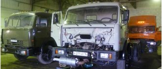
The specific features of the dump truck determine its popularity not only in construction, but also when carrying out minor repairs with the need to replace or rebuild any large-scale elements that require the removal of waste and the supply of new materials in large quantities, as well as in agriculture.
Such malfunctions are quite rare, however, they can also occur. It is possible to equip vehicles with electrical equipment with type markings that differ from those specified in this Manual. Wheel formula 6x4, engine power l.
Electrical diagram of the power supply system Two rechargeable lithium-ion batteries are used to store the generated energy. If you do not have a WebMoney wallet and you want to pay in another way, you need to select any of the methods that WebMoney offers and make the payment. After specifying the payment details and confirming the payment, payment for the goods will occur.
The remaining sections of the electrical circuit are checked in the same way. Quick check of the generator outside the car
Description of the circuit operation.
The electrical circuit diagram of all such cars is identical and differs only in design. The KamAZ brake light circuit includes sensors, an intermediate relay, a buzzer and a parking brake warning lamp, and of course warning lamps in the rear lights of the tractor and trailer.
The sensors are installed on the brake system circuits in the area of the brake valve and are triggered when the pressure in the circuit changes. On the latest models, a push-button switch installed under the pedal is used as a brake light sensor, as on most cars. When you press the pedal, the pressure in any of the circuits changes, which leads to the closure of the sensor contacts. If there is a push-button switch, the contacts close mechanically due to the action on the button. In this case, the intermediate relay winding is connected to the vehicle ground. In this case, the current from the fuse passes through the relay winding, the contacts of one of the sensors or the switch under the pedal. The relay contacts close and supply power to the warning lamps in the rear lights.
When the parking brake is applied, in addition to the warning lights, the parking brake warning light begins to flash. This occurs due to the fact that the parking brake switch and control lamp receive a minus signal through the parking brake sensor.
Since all sensors are connected to the intermediate relay coil, when any sensor is shorted, a minus appears on all sensors. In order to prevent the warning lamp from turning on when other sensors are triggered, a diode is included in the circuit, which prevents the minus from reaching the parking brake sensor wire.
Electrical circuit malfunctions.
During operation, some malfunctions are possible. The most common, for all cars, is when the brake warning lights do not light up. In this case, you need to check whether the lamps are lit when the parking brake is applied or not.
If the lamps are on, then the sensor is faulty or the wire from it to the relay is broken. To check, you need to disconnect the wire from the sensor and connect it to the vehicle ground. If the warning lights come on, the sensor is faulty. Otherwise, there is a break in the wire. If the lamps do not light up when the parking brake is applied, it is necessary to check the serviceability of the fuse, warning lamps and relays. Defective elements must be replaced.
The cause of the malfunction may also be a break in the wire connecting the relay to the warning lamps. If the warning lights come on when you press the brake pedal, but do not light up when you apply the parking brake, then you need to check the serviceability of the sensor, connecting wire and diode. It’s better to start by checking the diode, which is located on the board of the instrument panel warning lights, near the parking brake control paw. If, when applying the parking brake, a minus appears on the diode, then the sensor and connecting wire are in good condition. Otherwise, you need to disconnect the wire from the sensor and connect it to the vehicle ground. If a minus sign does not appear on the diode, then it is necessary to eliminate the break in the wire; if it appears, replace the sensor.
Another malfunction is when the warning lights are constantly on. Unlike those described earlier, this is typical only for the KamAZ stop signal. There may be several reasons. The first is the shorting of the positive wire to the signal lamp wire; in practice, it occurs if the wiring was melted in the process of shorting the positive wire to the ground of the car. The second reason is sticking of the signal lamp relay contacts.
To check, just remove and put this relay back into the socket. If the relay is working properly, a characteristic click will be heard. A faulty relay must be replaced.
Electrical system of KAMAZ-6511, 6520, 5510 and 5511: required diagram and wiring description
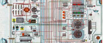
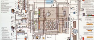
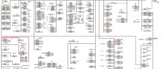
To connect all the electrical systems and devices in the car, an electrical network is used, which allows you to bring all the components together. The KAMAZ-65115 color wiring diagram is a diagram indicating all electrical elements, the use of which is important when repairing wiring. You can learn more about the elements of the circuit, as well as wiring faults, from this material.
Glass cleaning and auxiliary heater
The windshield is cleaned by brushes driven by an electric motor.
It has two rotor speeds. The wiper motor is controlled by a combination switch. The windshield wiper system includes an electric washer motor.
To maintain the required temperature in the cabin, KamAZ 431185 is equipped with an autonomous heater. Air circulation through the heating radiator is carried out using an electric fan.
From the above it follows that the KamAZ 43118 color wiring diagram is necessary for performing maintenance and repair of electrical equipment. The machine's wiring consists of several subsystems. The wiring is protected by fuses.
Features of electrical equipment
Now let's move on to the description of the KAMAZ electrical circuit.
All models of KAMAZ 6520, 55102 and other trucks are equipped with the following subsystems:
- Starting the power unit.
- Turning lights and hazard warning lights.
- Heating unit, power supply system, windshield cleaning mechanism.
- Vehicle interior lighting.
- Head lighting. It includes low and high beam headlights, fog lights if they are installed on the car, brake lights, and dimensions.
- Tidy. This node is considered one of the main ones in the on-board network, since it contains the main sensors, devices and instruments, including a tachometer, speedometer, fuel level sensor, etc. In addition, the control panel has light indicators that turn on when the lighting is activated , handbrake, etc. Thanks to the indicators, the driver can indirectly determine the status of some components.
- Vehicle anti-theft system, if installed.
- Fuse block. This component protects the car's electrical circuits from possible voltage surges. It contains fuses responsible for the operation of the main electrical equipment.
- A control unit, thanks to which the normal operation of the main units and equipment of the car is guaranteed.
- Audio system, if the car is equipped with one.
In order for the KAMAZ electrical circuit to operate in normal mode, the condition of the wiring must be at least satisfactory.
In addition, the operation of the electrical circuit is possible if:
- Rechargeable batteries. There are two of them in KAMAZ vehicles, they are connected to each other in series. The positive terminal of the battery is connected to the starter terminal, and the negative terminal is connected to the switch, and through it to the vehicle body. Both batteries are mounted in a special box located on the machine frame, behind the cab. Thanks to the batteries, normal operation of the ignition is ensured when the engine starts. In addition, thanks to the battery, it is possible to operate electrical equipment when the engine is turned off.
- Generator. The generator unit allows you to power electrical devices and systems while the engine is running. In addition, the battery is charged using the generator unit.
Consumer power
Power supply to consumers is provided by two batteries and a DC generator. The batteries and the generator are connected in parallel in the circuit. The negative wire from the battery is connected to the car body via a ground switch. It has a remote control and, if necessary, disconnects the battery terminal and the car body.
The on-board power supply voltage is 24 volts. To do this, 2 12-volt batteries are installed, which are connected in series with a jumper. Batteries are necessary to supply electricity to consumers when the internal combustion engine is turned off. After starting the power plant, consumers are powered from a DC generator.
ATTENTION: To prevent fire in the event of a short circuit, the electrical wiring is equipped with a fuse box.
How to determine the malfunction?
There are several options for diagnosing the health of a car's electrical circuit, which can be done at home. For example, you can check the presence of voltage in a certain area; for this you can use a multimeter or a test light.
So, if the circuit is faulty, the procedure is as follows:
- First, you need to connect one of the probes of the tester or warning lamp to the “-” terminal of the battery; it can also be connected to the truck body.
- The second probe must be connected to the connection of the area being diagnosed, and it is desirable that it be installed as close as possible to either the battery or the fuse.
- If, as a result of the connection, the control light starts to light up or voltage appears on the multimeter display, this means that this section of the circuit is working normally. That is, all elements are connected as needed, and no wiring repairs are required. But it must be taken into account that in some circuits voltage may be present if the ignition key is turned to a certain position.
- Next, the remaining sections of the circuit are diagnosed, the procedure is carried out in a similar way.
- If you find a point where there is no voltage, then most likely the cause of the problem lies between this point and the last area where there is voltage.
- It should be noted that in most cases, problems with wiring are caused by poor contact.
Troubleshooting in the KamAZ electric starting system
The engine starting system of a KamAZ vehicle can be in three alternative states: serviceable, operational and faulty (failure).
When in good condition, the starting system ensures the engine starts, and the condition of all devices meets the requirements of the technical specifications.
When in working order, the system ensures reliable engine starting, but the technical condition of some devices does not meet the technical conditions.
In the event of a malfunction (failure), starting the engine is impossible due to a malfunction of one or more system devices.
We will not consider the serviceable state of the system, since we are not tasked with determining the failure-free operation period of the system by the number of starts or by the mileage of the vehicle. To perform most tasks, it is enough to have the system in working order, when the system ensures reliable engine starting. Therefore, first of all, we will consider system failure and possible malfunctions, and indicate ways to quickly identify and eliminate them.
The system consists of seven devices, each of which affects the operation of the entire system. Therefore, in order to optimize the troubleshooting process, it is necessary to time each test and evaluate its impact on the performance of the starting system:
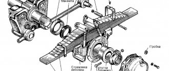
Checking batteries
Remove the cover from the battery socket. By external inspection, check the condition of the terminals of the tips and the tightness of their fastening to the pole terminals (Fig. 1). Based on the density of the electrolyte, the degree of discharge of the battery should be determined. Check time is about 5 minutes;
Checking the presence of voltage on the ammeter
Unscrew the bolts securing the prior shield and tilt the shield towards you or place it on the steering column. In this case, free access to the ammeter leads is available. Connect a test light in series to the input and output of the ammeter. If the light on the “+” of the ammeter is on, then the circuit up to the ammeter is working, and vice versa. Then check the “-” ammeter. If the control lamp is on, it means that current is passing through the ammeter, and faults should be looked for further along the circuit. If the light does not light, then the ammeter is faulty. This test without replacing the ammeter takes up to 2 minutes;
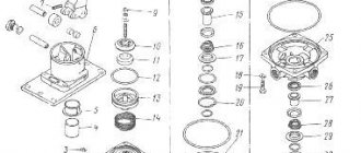
Checking the instrument switch and starter
Before checking this device, it is necessary to carry out preparatory work to ensure access to the terminals. To do this, you need to remove the guard panel for the electric motors of the cabin heating system, unscrew the nut securing the instrument switch and starter and remove the device from the panel, leaving it on the wires (Fig. 2). Remove the red wire from the “AM” terminal and check the presence of voltage with a test lamp. If the lamp is on, it means that the circuit to the instrument switch and starter is working. Then you need to connect the red wire to the “AM” terminal, turn the key in the instrument and starter switch to the second position and check the “ST” terminal (green wire) with a light bulb. If the lamp is on, it means that the instrument and starter switch is working properly.
Starter Interlock Relay
This relay is installed under the hinged fuse panel. The relay is assembled on semiconductor devices and it is impossible to check it with a test lamp. A special device is used for checking. A malfunction of the starter interlock relay does not necessarily lead to loss of functionality of the starting system, so this test should not always be performed when troubleshooting;
Possible wiring faults
Electrical wiring breakdowns are a problem that many of our compatriots face.
The following electrical circuit malfunctions are typical for KAMAZ 55111 and other models:
- If a device refuses to work, first of all it is necessary to diagnose the safety element. As mentioned above, the block contains devices for the normal operation of the equipment. So if a fuse fails, this may be due either to its wear and tear, which is quite normal, or to voltage fluctuations in the system. If the fuse was changed relatively recently, you need to make sure that its failure is not associated with power surges.
- Failure of the equipment itself. For example, if the stove or headlights do not work, but their electrical circuits are intact, and there are no short circuits or breaks in the wiring, then the heater itself may have broken down or the lighting lamp has burned out. Such malfunctions are quite rare, however, they can also occur.
- Charging the battery. If all the equipment immediately refuses to work, then perhaps the reason is a discharged battery or insufficient liquid level in its banks. It is necessary to check the charge of the device, as well as the electrolyte level.
- Another problem that can occur is the generator failing or not working properly. Since this unit is responsible for the performance of all equipment while driving, you will immediately know about its breakdown. Insufficient voltage in the on-board network may be due to weak tension of its belt; perhaps, by tightening the belt, you can correct the situation. But if the malfunction consists of wear or failure of the structural elements, then the generator unit will have to be removed and repaired.
- Current leakage, which is usually associated with a breakdown of the wiring insulation. Using a tester, you can identify a bad wire and change it. When replacing wiring, remember that it is better to insulate the cable several times before installation.
- Lack of contact between the device and the wiring. In this case, the reasons may be different. Perhaps the lack of contact is due to a wiring break, contact burnout, or oxidation directly at the terminal. In case of burning and oxidation, the fault can be eliminated by cleaning or replacing the contact.
External and internal lighting
External lighting includes headlights and side lights. The exterior lighting is controlled by a combination switch mounted on the steering column.
REFERENCE: External lighting includes the lampshade, the space under the KamAZ 43118 body and the engine compartment lighting lamp.
The KamAZ 43118 electrical circuit includes interior lighting in the form of a lamp installed in the cabin and dashboard lighting. It is possible to adjust the brightness of the backlight.
Relay box behind switch panel
p, blockquote 8,0,0,0,0 —>
Scheme
p, blockquote 9,0,0,0,0 —>
p, blockquote 10,0,0,0,0 —>
Purpose
p, blockquote 11,0,0,0,0 —>
- ABS relay
- Starter Interlock Relay
- Brake relay
- Clutch relay
- Fuel heating relay
- EFU relay
- Daytime running light relay
- Platform Stop Sensor Relay
- Rear fog lamp relay
- Oil separator relay.
Kamaz starter lock relay
Bibliographic link to the article:
// Modern equipment and technologies. 2012. No. 5 [Electronic resource]. URL: https://technology.snauka.ru/2012/05/946 (date of access: 06/07/2018).
Ph.D. tech. Sciences Gumelev V.Yu.,
Ph.D. tech. Sciences Kartukov A.G.,
The starter blocking relay 2612.3747 is used to automatically turn off and block the starter when the engine is running. It is installed on engines of vehicles of the KamAZ and URAL families [1, 2].
Second relay block
Scheme
p, blockquote 20,0,0,0,0 —>
p, blockquote 21,0,0,0,0 —>
Decoding
p, blockquote 22,0,0,0,0 —>
- power control relay after locking the instrument switch and starter
- instrument switch and starter relay
- battery switch relay
- brake signal relay
- reverse relay
- horn relay
- low beam relay
- high beam relay
- rear fog lamp relay
- fog light relay
- side light relay
Fuse F1
Scheme
p, blockquote 23,0,0,1,0 —>
p, blockquote 24,0,0,0,0 —>
Description
p, blockquote 25,0,0,0,0 —>
- nutrition
- radio equipment
- ECU circuit wiring harness
- to fuse block F2
- dryer cable
- instrument and starter switch
- starter relay
- to fuse block F3 after the instrument switch and starter
- to fuse block F3 to the instrument switch and starter
- fuse 60 A
- fuse 30 A