On vehicles with engines of environmental class 5 and 6, an electronic control unit for electrical equipment (ECU) is installed (see Fig. Location of fuses and relays with an electronic control unit).
Location of fuses and relays with electronic control unit
1 - Relay behind the switch panel; 2 - fuse block (F3, F7, F6); 3 — electronic control unit for electrical equipment; 4 - fuse F1, 5 - horn relay; 6 — relay for turning on the coupling headlight; 7 – starter relay; 8 – alarm relay.
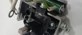
Relay behind switch panel
Relay behind the switch panel for vehicles with engines of environmental class 5 1 - ECU relay (for certain configurations); 2 — ECU relay (for individual configurations); 3 — braking relay; 4 — fuel heating relay; 5 — relay for switching on instruments and starter; 6 — battery switch relay; 7 - power control relay after locking the instrument switch and starter; 8 - 12 V socket relay; 9 — windshield wiper stop relay; 10 - radio disconnect relay
Relay behind the switch panel for vehicles with engines of environmental class 6 1 - Clutch relay; 2 — starter blocking relay; 3 — pump power relay; 4 — relay for the heated line to the nozzle; 5 — relay for the heated line from the pump to the tank; 6 — fuel heating relay; 7 — relay for switching on instruments and starter; 8 — battery switch relay; 9 — power control relay after locking the instrument switch and starter; 10 - 12 V socket relay; 11 – relay for the heated line from the tank to the pump; 12 — radio disconnect relay; 13 — windshield wiper stop relay; 14 - heater relay
The main symptoms of a malfunctioning starter
To determine possible starter malfunctions, you will have to pay attention to its behavior, as well as the sounds it makes.
- So, if the traction relay is activated, but the crankshaft does not turn, let's start by checking the battery charge. The reason may be that the brushes or commutator are clogged with dirt and dust. In this case, the traction relay itself may have burnt or oxidized contacts.
- After the engine starts, the starter armature may continue to rotate. This may mean that the relay springs are broken and need to be replaced with new ones. Welding of the contact disc to the bolts may occur. In this case, we will need a KAMAZ wiring diagram in order to clean the disk itself and the bolts, or replace them. If necessary, the starter interlock relay may need to be replaced.
- Another situation is that when you try to start, characteristic clicks are observed that the traction relay makes. In this case, you need to start by checking the contact connections in the circuit of the relay itself and restoring the reliability of the contacts. If necessary, it may be necessary to replace the retractor itself.
Note! There may be no contact between the brushes and the commutator, in which case either the brushes themselves or their springs are replaced.
- If the wiring on the KAMAZ was assembled with a violation of the contact adjustment at the moment of closing, turning on the starter will be accompanied by the grinding of the drive gear. You will need to adjust the gap between the thrust washer and the gear. When you try to start the engine, gears may grind, but the engine will not start.
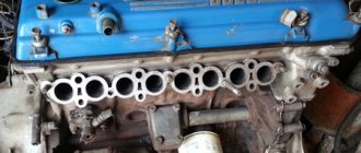
We visually check the condition of the contacts and wiring harnesses.
This means that the issue may be an incorrectly adjusted moment of closing the contacts of the traction relay . Or the ends of the teeth of the flywheel gear or drive are clogged. In this case, you will have to either replace the gears with new ones or try to restore the teeth. They are reanimated by surfacing.
Tip: At a minimum, try to smooth out any rough spots on them first.
It is possible that the armature continues to rotate, but the crankshaft does not rotate, which means that there is no interaction between them. First of all, check that the starter is adjusted correctly. After this, make sure that the teeth of the drive gears and the flywheel ring are in unworn condition.
We begin to dismantle the KAMAZ starter
In order to carry out repair work, we will need a special stand on which we will disassemble this unit, and a KAMAZ electrical wiring diagram.
The diagram is clickable - 1600x1088
Dismantling this block begins with turning off the ground. If difficulties arise, read the article problem with the “mass” on our website.
After this, we raise the cab and disconnect the wiring that goes to the starter relay.
So, our actions will be as follows:
- unscrew the nuts on the starter housing and on the relay cover;
- remove the jumpers connecting the exciter winding and the output bolt of the traction relay;
- Next, you need to unscrew the nuts securing the traverse, located on the collector side;
- unscrew the lock washers;
- remove the cover from the side of the collector after unscrewing the bolts;
- Unscrew the screws that secure the brushes to the traverse;
- you can finally remove the brushes themselves;
- Unscrew the screw of the adjusting flange and dismantle the lever axis;
- the drive cover is secured with a screw - unscrew it;
- remove the relay simultaneously with the anchor;
- bend the lock washers and unscrew the bolts;
- we dismantle the drive cover simultaneously with the drive itself and the lever;
- We finish by removing the thrust washer, after which the starter armature is removed.
Now the device is ready for diagnostics or repair, if the rest of the wiring on the KAMAZ is in good condition.
What to pay attention to
How to check a disassembled starter
Let's look at the main stages of testing functionality:
- Checking the traction relay. To do this, we bring the “+” from the battery directly to the terminal that draws in the relay winding. The relay will be operational if a click is heard and the motor rotates. If the engine does not rotate, then you need to check with a test lamp whether there is voltage at the contact bolt. Civilian owners also need a similar check.
Important! If the lamp is on, it means the relay is working properly.
- Checking the starter switch relay. It is located under the fuse panel. We bring “+” to terminal “K”. If there are clicks from the contacts and the indicator lamp lights up when connected to a black wire, this indicates that the switching relay is working.
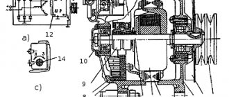
Internal elements of the starting device
- Checking the device locking relay. It cannot be checked with a conventional test lamp, because... it is assembled from semiconductor devices. Its performance can only be determined using a special device. However, its failure will not necessarily lead to engine starting problems.
- Checking the starter motor. It is necessary to check its serviceability on a stand, in disassembled form. This procedure is the most complex and time-consuming and takes about half an hour.
As a rule, the performance of this starting device is checked by factors such as the amount of current used and the idle speed. The obtained data is compared with those provided for this type of starter.
Fuse F5
Fuse F5 is installed on the front panel of the cab.
Fuse F5 1 - to fuse block F4; 2 - fuse F5; 3 - jumper; 4 — “Generator-fuse” wire; 5 — wire “Battery - fuse”; 6 - fuse wire; 7 - to fuse block F1; 8 - fuse wire
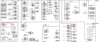
Electrical circuits of KamAZ have a single list of elements; the location zones of elements in semi-assembled circuits may differ slightly (Fig. 328-337).
Auxiliary brake sensor MM125D-3810600 TU37.003.546-76
Fuel level sensor SYAMI 407 611-114-01 (or SYAMI 407 611-114-02) TU4573-002-12258598-93
Speedometer sensor 2001.3843 TU37.003.1270-75
How to determine the malfunction?
Detecting breakdowns in equipment operation is possible with the involvement of a specialist or at home.
In general, there are two vehicle conditions in which a circuit failure can be determined:
- The engine does not start and the vehicle cannot be operated. There can be many reasons for the breakdown in this case. Equipment diagnostics should begin with the switchgear, spark plugs, high-voltage wires, starter unit and, of course, the battery. In most cases, the cause can be solved by charging the battery or replacing high-voltage wires. In addition, the reason may be a failed generator. Before you begin dismantling and disassembling the unit, you should check the quality of the generator belt tension. Perhaps the strap is loose or its tension is very strong, which is also not very good for the car.
- The engine can be started, but the equipment does not work or only works partially. A group of devices may not be working. For example, in your car the turn signal and windshield wiper blades stopped working at the same time. It would seem, how can these devices be connected to each other? But you need to take into account that these two systems operate from the steering column switch. And if it fails or there is a bad contact on its circuit, then the nodes simply cannot be started. If the engine starts, then some of the components do not work, then you should first check the fuses in the block; it is quite possible that one or part of them has simply blown. If the safety elements are working, and you are 100% sure that the electrical equipment is working, then you need to start diagnosing the wiring (the author of the video is the CarEnergy channel).
Consumer power
Power supply to consumers is provided by two batteries and a DC generator. The batteries and the generator are connected in parallel in the circuit. The negative wire from the battery is connected to the car body via a ground switch. It has a remote control and, if necessary, disconnects the battery terminal and the car body.
The on-board power supply voltage is 24 volts. To do this, 2 12-volt batteries are installed, which are connected in series with a jumper. Batteries are necessary to supply electricity to consumers when the internal combustion engine is turned off. After starting the power plant, consumers are powered from a DC generator.
ATTENTION: To prevent fire in the event of a short circuit, the electrical wiring is equipped with a fuse box.
KAMAZ electrical wiring to help when troubleshooting and replacing the starter
KAMAZ trucks are equipped with a St-142b starter with a voltage of 24V and an idle current of up to 130 Amperes. To start it, you need to turn the key to a non-locking position. As soon as the start has taken place, the key is released.
Its action goes like this:
- The current from the batteries passing through the traction relay engages the flywheel ring gear and the drive gear while simultaneously closing the starter power contacts.
- rotation of the armature is created with transmission of torque to the flywheel through the drive gear.
- they are disconnected after the engine begins to operate in autonomous mode.
Light signaling model 431185
In order to safely use the car and indicate the maneuvers being performed, the manufacturer equipped the model with a light signaling system. Light alarms include:
- Direction indicators;
- Alarm;
- Car brake lights;
- Lamp for reversing vehicle;
- Road train lights.
The blinking of the direction indicator lamps is carried out due to the operation of the breaker relay. The turn signal and hazard warning relays are housed in one housing.
Turning on the direction indicators is carried out using a combination switch located on the steering column of the car. A separate switch is provided to turn on the hazard warning lights.
The brake lights are switched on using a pneumatically driven switch. When you press the brake pedal, compressed air pressure acts on the switch membrane. The membrane closes the contacts for turning on the brake lights.
IMPORTANT: Thanks to the pneumatic drive of the switch, the brake lights come on both in the service brake system mode and when the parking brake is applied.
Trailer lights are used to identify a vehicle and trailer on public roads. The lights are turned on by a switch located on the front panel of the car. You can also read about KamAZ 55111.
External and internal lighting
External lighting includes headlights and side lights. The exterior lighting is controlled by a combination switch mounted on the steering column.
REFERENCE: External lighting includes the lampshade, the space under the KamAZ 43118 body and the engine compartment lighting lamp.
The KamAZ 43118 electrical circuit includes interior lighting in the form of a lamp installed in the cabin and dashboard lighting. It is possible to adjust the brightness of the backlight.
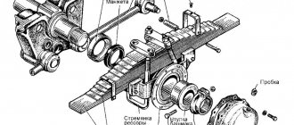
Anchor
As for the anchor, it includes the following elements:
The latter is made from sheets of electrical steel. The manifold is designed to maintain constant torque. The winding is wave type. 2 wires are placed in the grooves with a core.
Moreover, their turns are isolated from the core. The end of the wires is placed in the slot in the copper plate of the collector and soldered.
Glass cleaning and auxiliary heater
The windshield is cleaned by brushes driven by an electric motor.
It has two rotor speeds. The wiper motor is controlled by a combination switch. The windshield wiper system includes an electric washer motor.
To maintain the required temperature in the cabin, KamAZ 431185 is equipped with an autonomous heater. Air circulation through the heating radiator is carried out using an electric fan.
From the above it follows that the KamAZ 43118 color wiring diagram is necessary for performing maintenance and repair of electrical equipment. The machine's wiring consists of several subsystems. The wiring is protected by fuses.
Other electrical circuit features
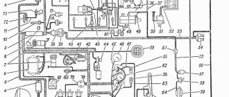
The KamAZ-5320 color wiring diagram shows:
- two 6ST-190TR brand batteries;
- remote switch type VK-860;
- switch button inside the cabin;
- remote switch “Thermostart”;
- a relay that is responsible for disconnecting the device’s power-on wires;
- device that generates energy: G-272;
- a device that regulates voltage;
- fuse;
- starter and device switch;
- contactor;
- special ammeter.
The main feature of the electrical equipment of the KamAZ-5320 is the presence of an additional device, with the help of which the platform is raised on the vehicle. The circuit contains the following components:
- two solenoid valves for raising and lowering the platform;
- hydraulic distribution solenoid valve;
- electromagnetic power take-off device;
- PTO switch;
- hydraulic distribution button.