Middle drive axle
General information.
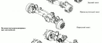
To reduce the load on the rear axle, two drive axles are used: middle (intermediate) and rear. On trucks with three axles, a center differential is installed.
Center differential.
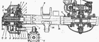
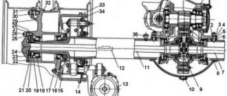
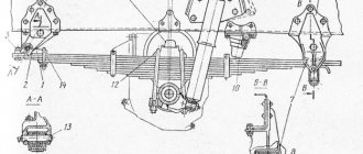
To distribute torque evenly between the two drive axles and reduce tire wear, a center differential is used, which is installed in the middle (intermediate) axle in a separate housing 13 (Fig. 8), attached to the main gear housing through the bearing housing of the drive bevel gear. The housing contains the rear 10 and front 11 cups, bevel gears 12 and 14 for driving the middle and rear axles, respectively, between which there is a cross 16 with satellites 15 mounted on bronze bushings. The differential locking mechanism is also located here, consisting of a locking clutch 9, fork 8 and diaphragm chamber 6. Clutch 9 is placed on an internal gear coupling, rigidly connected to bevel gear 12 of the middle axle main gear drive.
Locking mechanism
.
Designed for forced differential locking when driving on slippery and wet roads. When it is turned on by the handle of the control valve located in the cabin under the steering column, air from the pneumatic system enters the diaphragm chamber 6. The diaphragm bends, overcoming the resistance of the spring, and moves the rod 7
with the fork and the locking clutch 9 forward. The latter finds splines on the gear ring of the rear differential cup and blocks it, rigidly connecting the differential housing with bevel gear 12. The blocking should be applied at low vehicle speeds or before starting to move.
When the locking mechanism is turned off, the air from under the diaphragm of chamber 6 escapes into the atmosphere, and the diaphragm spring moves the rod, fork and coupling to its original starting position.
Rice. 8. Middle (intermediate) axle and center differential of a KamAZ vehicle:
1 — intermediate axle differential; 2 and 18 - driving and driven cylindrical gears, respectively; 3 — driven bevel gear; 4 — rear axle drive shaft; 5
- drive bevel gear of the intermediate bridge; 6 - diaphragm chamber;
7
— rod;
8 - fork; 9
— differential lock clutch; 10 - rear cup; 11 — front cup with drive shaft; 12 — bevel gear of the middle axle drive; 13 — body;
14 — bevel gear of the rear axle drive; 15 — satellite; 16 — cross; 17 — left axle shaft; 19 — crankcase; 20 — right axle shaft of the intermediate bridge
When driving on dry paved roads, you should not lock the center differential, as this results in increased tire wear and excessive fuel consumption.
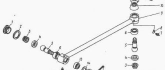
Axle shafts 17 and 20 (see Fig. of the intermediate bridge) are installed in the axle housing and are made with splines at the ends. The differential side gears are mounted on the axle shafts with splined holes. The outer ends of the axle shafts are connected by flanges to the hubs of drive wheels 1 (Fig. 9)
Depending on the nature of the installation of the axle shafts in the axle housing, they can be completely or partially unloaded from bending moments arising under the influence of forces acting on the wheel.
On trucks, fully balanced axle shafts are used. Such an axle shaft is only affected by torque, and all other forces are perceived by the axle shaft casing, since the wheel hub is mounted on bearings mounted directly on the casing.
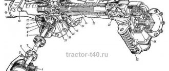
Rice. 9. Schemes of axle shafts:
a - semi-loaded axle shaft; b - completely unloaded axle shaft;
1 - drive wheel; 2 - axle shaft; 3 - casing; 4 - bearing; 5
— hub; G is the force acting on the casing and axle shaft; M - torque
General information.
To reduce the load on the rear axle, two drive axles are used: middle (intermediate) and rear. On trucks with three axles, a center differential is installed.
Center differential.
To distribute torque evenly between the two drive axles and reduce tire wear, a center differential is used, which is installed in the middle (intermediate) axle in a separate housing 13 (Fig. 8), attached to the main gear housing through the bearing housing of the drive bevel gear. The housing contains the rear 10 and front 11 cups, bevel gears 12 and 14 for driving the middle and rear axles, respectively, between which there is a cross 16 with satellites 15 mounted on bronze bushings. The differential locking mechanism is also located here, consisting of a locking clutch 9, fork 8 and diaphragm chamber 6. Clutch 9 is placed on an internal gear coupling, rigidly connected to bevel gear 12 of the middle axle main gear drive.
Locking mechanism
.
Designed for forced differential locking when driving on slippery and wet roads. When it is turned on by the handle of the control valve located in the cabin under the steering column, air from the pneumatic system enters the diaphragm chamber 6. The diaphragm bends, overcoming the resistance of the spring, and moves the rod 7
with the fork and the locking clutch 9 forward. The latter finds splines on the gear ring of the rear differential cup and blocks it, rigidly connecting the differential housing with bevel gear 12. The blocking should be applied at low vehicle speeds or before starting to move.
When the locking mechanism is turned off, the air from under the diaphragm of chamber 6 escapes into the atmosphere, and the diaphragm spring moves the rod, fork and coupling to its original starting position.
Rice. 8. Middle (intermediate) axle and center differential of a KamAZ vehicle:
1 — intermediate axle differential; 2 and 18 - driving and driven cylindrical gears, respectively; 3 — driven bevel gear; 4 — rear axle drive shaft; 5
- drive bevel gear of the intermediate bridge; 6 - diaphragm chamber;
7
— rod;
8 - fork; 9
— differential lock clutch; 10 - rear cup; 11 — front cup with drive shaft; 12 — bevel gear of the middle axle drive; 13 — body;
14 — bevel gear of the rear axle drive; 15 — satellite; 16 — cross; 17 — left axle shaft; 19 — crankcase; 20 — right axle shaft of the intermediate bridge
When driving on dry paved roads, you should not lock the center differential, as this results in increased tire wear and excessive fuel consumption.
Axle shafts 17 and 20 (see Fig. of the intermediate bridge) are installed in the axle housing and are made with splines at the ends. The differential side gears are mounted on the axle shafts with splined holes. The outer ends of the axle shafts are connected by flanges to the hubs of drive wheels 1 (Fig. 9)
Depending on the nature of the installation of the axle shafts in the axle housing, they can be completely or partially unloaded from bending moments arising under the influence of forces acting on the wheel.
On trucks, fully balanced axle shafts are used. Such an axle shaft is only affected by torque, and all other forces are perceived by the axle shaft casing, since the wheel hub is mounted on bearings mounted directly on the casing.
Rice. 9. Schemes of axle shafts:
a - semi-loaded axle shaft; b - completely unloaded axle shaft;
1 - drive wheel; 2 - axle shaft; 3 - casing; 4 - bearing; 5
— hub; G is the force acting on the casing and axle shaft; M - torque
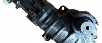
Rear axle gearbox KamAZ 43118 diagram
Quick links (click): Price for KamAZ 43118 rear axle gearbox diagram DELIVERY IN RF WARRANTY 6 MONTHS
WATCH A VIDEO!!!
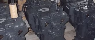
Our company specializes in: - trade in spare parts for KAMAZ vehicles; — sales of new factory gearboxes produced by KAMAZ OJSC; — repair of KAMAZ gearboxes (experienced professionals will do high-quality repairs, you will be happy); — sale of repair KamAZ gearboxes assembled from new components on a used crankcase (there is no point in overpaying for a new gearbox produced by KAMAZ OJSC when our main gears will be used no less than the factory ones).
We will send the KamAZ 43118 rear axle gearbox diagram throughout the Russian Federation and Kazakhstan: Sochi Novosibirsk Segezha Stary Oskol Klin Tuymazy Chita. Magadan Berdsk Sovetsky Lisichansk Syktyvkar Pskov Moscow Nalchik. Nikolaev Ulan-Ude Ussuriysk Dedovsk Omsk Orekhovo-Zuevo Rossosh Domodedovo Bratsk. Yakutsk Astrakhan Liski. Irkutsk Armavir Taishet Kharkov Tolyatti Kirov Sumy Sovetsk Kropotkin Novy Urengoy Gomel Tver Vladimir Astana Ust-Ilimsk Kirensk Troitsk Chekhov Lipetsk Belgorod Angarsk Kimry Kurgan Vladikavkaz Grodno Komsomolsk-on-Amur Abakan Yelets Dimitrovgrad Blagoveshchensk Smolensk Kostanay Nadym Brovary Kumertau Glazov Penza Uralsk Nizhnyaya Tura Taganrog Gatchina Volkhov . Dzerzhinsk Buzuluk. Zhukovsky Krasnoturinsk Shebekino Orsk Malin Rostov-on-Don Rudny Kostroma Nizhny Tagil Ekaterinburg Kaliningrad Achinsk. Vsevolozhsk Ivanovo. Ufa. Dnepr Sestroretsk Samara Inta Tomsk Voznesensk Chernivtsi Grozny Nyagan Dmitrov Petropavlovsk Arzamas Georgievsk Solnechnogorsk Cheboksary. Nevinnomyssk Bryansk Vologda Prokopyevsk Noyabrsk Stavropol Karaganda Nefteyugansk Mikhailovka Krivoy Rog Kogalym. Kokshetau Barnaul Usinsk Chisinau Petrozavodsk Kyzyl Gelendzhik Belorechensk. Krasnodar Neftekamsk Labinsk Chelyabinsk Saransk Verkhnyaya Salda Yuzhno-Sakhalinsk Minsk Vidnoye Lomonosov Naberezhnye Chelny Perm Saratov Kazan Oktyabrsky Lobnya Voronezh Zlatoust Novorossiysk Ryazan Chernigov Kropivnitsky Veliky Novgorod Khabarovsk. Kotlas Norilsk Miass Lukhovitsy Salavat Kramatorsk Iskitim Podolsk Nizhnevartovsk Magnitogorsk Novokuznetsk Kaluga Aktobe. Langepas Semikarakorsk Kandalaksha Sergiev Posad Melitopol Kherson. Sizran. Volgodonsk Lakes Satka. Tuapse Uman Salekhard Arkhangelsk. Makhachkala Krasnoyarsk Zelenograd Vladivostok Volgograd. St. Petersburg Surgut Volzhsky Balashikha Sterlitamak Olenegorsk Yoshkar-Ola Vinnitsa Mirny Cherkassy Tula Khanty-Mansiysk Ulyanovsk Kursk Mineralnye Vody Lyubertsy Tyumen Murmansk Berdyansk Serpukhov Naryan-Mar Mines Biysk Kemerovo Murom Elista Orenburg Velikie Luki Reutov Zaporozhye Alexandrov Slavyansk Orel Tem ryuk Voskresensk Khimki Poltava Cherepovets Atyrau. Izhevsk Zhirnovsk Ust-Kut Verkhnyaya Pyshma Simferopol Tambov Severodonetsk Yaroslavl Ukhta Nizhny Novgorod Almaty Aldan Yeniseisk Mytishchi Lesosibirsk, etc.
Rear axle gearbox KamAZ 43118 diagram
How to reassemble
The assembly process is carried out in the reverse order of the dismantling described above:
- The transfer case returns to the installation area and is raised by the lift to its previous height.
- Align the holes of the RC and the supporting structure to screw the bolts and nuts back into place.
- Pneumatic hoses are attached.
- The ground wire and control lighting wires are connected.
- Speedometer plug, driveshafts are attached.
Please note that when installing cardan shafts, it is necessary to tighten the self-locking nuts to the required torque values according to the instructions; for this you need to use special torque wrenches. When the transfer case is installed, oil is poured back into the housing through the hole. The oil level must correspond to the position of the lower control plug.
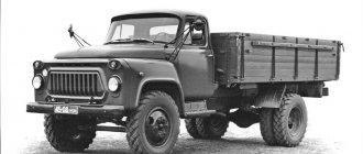
The KamAZ-4310, 43118 car is reliable and proven over long kilometers of Russian roads. It is believed that this is a car with increased cross-country ability, produced at the Kama Automobile Plant since the beginning of 1981. At first, these cars were supposed to be used for the needs of the Secular Army, but then they were firmly entrenched in the national economy. Now they are confidently winning competitions, proving the indisputable advantage of our cars.
How does a transfer case work?
After turning on the switch, compressed air is not able to enter the pneumatic chambers, and therefore the diaphragms return to their original position. The torque between the shaft gears is transferred to the races and satellites. The gears, carried by the satellites, allow you to move along a good, damage-free road as a single unit. If the road becomes uneven, for example, off-road, the front axle and the bogie move differently, and then the epicycle with the sun gear rotates at different speeds, and the satellites rotate not only around the main axis, but also around their own axes.
Both gears can turn on at the same time, and to prevent this, a lock is supposed to prevent this from happening. If we take into account the differential lock, then when locked, the pneumatic chamber moves the clutch, which serves as a connecting element between the cage and the drive shaft on the front axle. This allows you to move on roads of different quality, both good and poor quality, as a single mechanism, the torque is proportionally distributed between the front axle and the bogie, as are the loads on them.
To eliminate the load on the transmission, the differential is constantly active, that is, unlocked. Only in a situation where you are driving on slippery roads should you use a lock, as this reduces the risk of wheel slipping and guarantees the safe movement of the vehicle.
Lubricating the RK is quite simple. It is enough to spray the oil, and about five liters of oil of a certain brand are poured into the crankcase.
Transfer case KAMAZ-4310,43118
Box device. The main components are the following:
- Carter;
- Main or drive shaft;
- Intermediate or secondary shaft;
- Shaft located on the front axle;
- Shaft for driving axles at the rear of the car;
- Shaft intended for power take-off;
- Center differential;
- Central control drive;
- The gear is responsible for overdrive.
Transfer case KamAZ 4310
The KAMAZ 4310, 43118 is equipped with a transfer case, usually two-stage, the differential on it is usually lockable and has an electro-pneumatic drive. In first gear the number is set to 1.692, in second – 0.917. The fastening of the box is usual, on rubber pads and brackets and is fixed on the frame spar, as well as on the cross members located between the two.
The crankcase on the KAMAZ 4310.43118 motor vehicle is made as a cast structure on which a vertical connector is located. A power take-off box is installed on the upper section of the crankcase using a hatch. This is the structure of the box.
The crankcase is closed with a lid; the manufacturer provides for oil filling through this connector, which is closed with a plug. The driver can easily check the level of consumed oil; this can be done through the lower hole, which is also equipped with a magnetic plug. The crankcase is protected on top by a lid, that is, the crankcase hatch, and it is intended for power take-off.
The operation of the drive shaft involves two types of bearings: ball bearings (1 piece) and cylindrical roller bearings (2 pieces). The bearings located in front have a seal, and the rear bearing is located inside the crankcase, in a special compartment.
There is a gear on the shaft; it is not only a drive gear, but it is also pressed in, and the gear responsible for power take-off is already welded onto the hub.
The intermediate shaft moves thanks to bearings, both roller and cylindrical, which are protected by covers. The intermediate gear, as well as the first gear, are fixed to the shaft and move differently on it. From the oil sump, which is located above the intermediate shaft, oil flows onto the gear rollers by gravity. Both gears have teeth embedded in them, and it is on them that the clutch is attached, which is responsible for the first gear, and specifically for engaging it.
How does a center differential work? As you know, the wheels of the front axle and the wheels on the trolley spin differently, especially if the movement occurs on an unpaved road, on a country road, or equipped only with crushed stone backing. The differential distributes the torque between them in a percentage ratio of 1:2; it is installed at the very bottom of the crankcase on two bearings: roller and cylindrical. Also provided:
- Main, drive gear;
- Rear clip, and front;
- Solar, as well as in a pair of epicyclic gears;
- Satellites.
Both cages are fixed on the drive gear, while the sun gear is located on the splines of the front axle shaft, and the epicyclic gear is paired with the bogie shaft. The satellites are mounted on bushings made of bronze, in the front differential race and support washer. Their task is to always be in conjunction with the gears, as mentioned above with the solar and epicyclic ones.
On the holder in front there are two roller bearings, and the gear responsible for second gear also rotates there. A gear coupling helps connect to the front cage. The coupling allows you to lock the differential, and on the front shaft of the axle drive there is a gear to drive the sensor, which reflects the readings of the speedometer, which is located on the crankcase.
Using the switch, which is located in the driver's cabin, you can control the gearbox (RK), the system is responsible for this action, which includes a switch, electric pneumatic valves, two pneumatic chambers and pneumatic actuators, and a sensor responsible for switching on.