Classic “loaf”
UAZ 3741 or 452, called by the people “loaf”, is the most famous creation of the Ulyanovsk Automobile and is remembered as a reliable ambulance, emergency gas service, police, water utility vehicle. She has many positive qualities. It is unpretentious in maintenance, has excellent maneuverability and endurance.
But for all its advantages, like any machine, sooner or later it needs partial or major repairs. For this purpose, it is not necessary to contact service centers. The structure of a domestic car is not very complicated, and you can figure out how to repair some of its parts yourself.
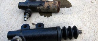
Repair kit for master brake cylinder
It was decided not to change it, but to purchase a repair kit for the main brake cylinder and repair it ourselves. After two days of operation, the cylinder literally jammed. After disassembling it turned out that the rubber bands were swollen. The same thing happened with the second repair kit. The third one lasted a week, but still refused, since the rubber bands had simply worn out.
The main brake was inspected for damage and scratches. We were unable to find anything suspicious. Repair kits were purchased in different price categories, in different stores, and everyone praised the product. Conclusion, they are selling Mr. It's a pity for the money spent, almost a third of the price of a new one.
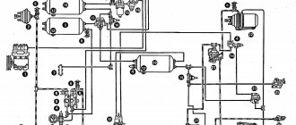
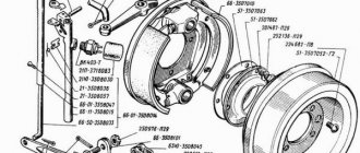
Working brake system of UAZ Bukhanka
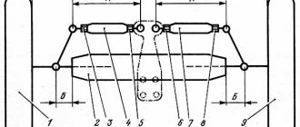
Service brake system diagram
The diagram allows you to study how the brake system of the UAZ Bukhanka works more clearly.
Fig. 1 Diagram of the working brake system of the UAZ Bukhanka: 1 – brake disc; 2 – front wheel brake bracket; 3 – outline of the front part; 4 – main brake cylinder; 5 – reservoir equipped with a brake fluid movement sensor to the emergency level; 6 – amplifier with vacuum; 7 – pusher; 8 – brake pedal; 9 – light switch when braking; 10 – rear wheel brake pads; 11 – rear wheel braking cylinder; 12 – outline of the rear part; 13 – casing of the axle axle at the rear; 14 – load spring; 15 – pressure regulator; 16 – rear cables; 17 – equalizer; 18 – central cable; 19 – parking brake lever; 20 – indicator of brake fluid movement to the emergency level; 21 – parking brake warning switch; 22 – front wheel brake pads.
Hydraulic drive of the service brake system
Since 1985, the hydraulic drive of the UAZ service brake system began to be produced with two separate branches, one of which extends to the brake mechanisms of the front wheels, and the second extends to the brake mechanisms of the rear wheels. The drive design includes:
- master brake cylinder;
- a brake pedal, which is connected to the cylinder through its piston;
- wheel cylinders of wheel brake mechanisms, both in the front and rear of the car;
- pipelines and hoses that connect all cylinders;
- control pedal and drive force amplifiers.
The lines, the inside of the master cylinder, and all wheel cylinders contain brake fluid.
When installing a brake force regulator and an anti-lock braking system modulator on a UAZ, they are also placed in the hydraulic drive structure.
The principle of operation of the UAZ brake system
When you press the pedal, the brake system operates in the following sequence:
- The master cylinder piston moves fluid into the lines and wheel cylinders;
- in the wheel cylinders, the brake fluid causes all the pistons to move, as a result of which the brake pads move closer to the drums;
- when there is no distance left between the pads and the drums, the release of fluid from the main brake cylinder will stop;
- When you press the pedal harder, the fluid pressure in the drive rises and braking of all wheels starts at the same time.
Greater force applied to the pedal results in greater pressure exerted by the master cylinder piston on the fluid, as well as greater force exerted by all the wheel cylinder pistons on the brake shoe.
This suggests that the simultaneous operation of all brakes and the regular relationship between the force on the brake pedal and the driving forces of the brakes are created thanks to the hydraulic drive system.
When the brake pedal is released, it returns to its original position due to the functioning of the return spring. In addition, due to the spring, the piston of the main brake cylinder also moves to its original position. And the tension springs of the mechanisms, in turn, move the pads away from the drums. Brake fluid from the wheel cylinders is pushed through pipelines into the master cylinder.
Advantages and disadvantages of hydraulic drive
Advantages of hydraulic drive:
- quick response provided by the impressive rigidity of the pipelines;
- high efficiency, since energy is wasted as a result of pouring low-viscosity liquid from one device to another;
- not a complex design;
- low weight and dimensions as a result of high driving pressure;
- comfortable layout of drive devices and pipelines;
- a chance to achieve the required distribution of braking forces among the vehicle axles, obtained due to the difference between the diameters of the pistons of the wheel cylinders.
Among the disadvantages of the hydraulic drive are:
- requires special brake fluid with a high boiling point and low thickening point;
- the threat of malfunctions due to depressurization as a result of liquid leakage when damaged, or malfunctions when filling the drive with air;
- a strong decrease in efficiency at low temperatures, usually below minus 30 °C.
Brake fluid
Special brake fluids are sold for use in hydraulic drives. They are produced on alcohol, glycol or oil bases. It is prohibited to mix them with each other; this can lead to a deterioration in their quality and the appearance of flakes. Brake fluids made from petroleum products may only be used in hydraulic drives whose seals and hoses are made of oil-resistant rubber. This is done in order to prevent the destruction of rubber parts.
Steering
On cars there is steering both with and without power steering, as well as steering columns with and without a cardan.
Adjusting the steering column
Adjusting the steering gear to remove play in the steering wheel proceeds as follows:
- Align the wheels straight and disconnect the steering rod from the bipod.
- Eliminate the gap between the worm and the roller using the adjusting screw.
- Return the lock washer to its place and tighten the screw so that the washer and pin match.
- Assemble the structure and check the adjustable steering column.
If it is not possible to achieve normal operation using adjustment methods, the UAZ steering column needs to be repaired.
Car owners sometimes install tuning steering shock absorbers. This improves the car's handling and road stability.
How to remove the steering wheel
Removing the steering wheel on a Bukhanka is a difficult task. In most cases, a special three-legged puller helps. It may take a few hits with a hammer on the steering wheel. It is advisable to pre-moisten the joint with kerosene or VD-40.
Parking brake system of UAZ vehicles
Parking mechanism diagram
Rice. 2 Parking brake system: a – view with brake drum; b – view without brake drum; 1 – adjustment fork; 2 – lock nut; 3 – drive rod; 4 – expansion cracker; 5 – plug; 6 – drive lever; 7 – adjustment screw; 8 – block support; 9 – pusher of the expansion unit; 10 – ball body; 11 – housing of the expansion unit; 12 – brake drum; 13 – first block; 14 – tension spring of pads; 15 – cap; 16 – expansion unit ball; 17 – bolt; 18 – second block; 19 – brake shield; 20 – housing of the adjustment mechanism; 21 – rod; 22 – spring; 23 – spring cup.
Operating principle of the parking mechanism
The brake mechanism of the parking system is equipped on the transfer case and brakes the rear propeller shaft of the Bukhanka. Its design includes a support disk with two pads installed on it, connected by springs. The pads act on the brake drum, which is fixed on the centering belt of the propeller shaft flange. Attached to the top of the support disk is the housing of the expansion unit with pushers, which are attached to the top of the pads. Inside, the pushers are equipped with recesses filled with balls that are located in the rod. The housing of the adjusting element is installed at the bottom of the support disk. The recesses of the housing contain pad supports that can move due to the work of the block and the adjusting screw.
The brake mechanism drive includes a lever mounted on the support disk and an expansion element supporting the rod of the balls. The free end of the lever is attached to the fork, which in turn is attached to the rod using a lock nut. The drive rod is attached to the parking brake lever, which is installed in the driver’s cab.
In addition, on the UAZ Bukhanka, the parking brake system drive is supplemented with an extension located between the parking brake lever and the brake mechanism. This extension cord is a steel cable with elements for its fastening.
Power unit
Since 2022, UAZ will be equipped with UMZ 421 engines in injection or carburetor versions. The most common engine breakdowns:
- Thermal clearances of the timing valves go away;
- the connecting rod bearings are rotated;
- the ignition system fails;
- The thermostat breaks;
- the pump does not pump;
- The engine is heating up.
Coolant replacement
After 2 years of operation or 60,000 km, the coolant in the car needs to be replaced. Replacement is carried out on a cold engine and on a level surface.
If there is crankcase protection, you will have to remove it. Open the heater tap, place the container and unscrew the cap on the radiator. We unscrew the cap of the expansion tank and the plug in the cylinder block.
You can use water to flush the system several times. Fill the antifreeze through the expansion tank, start and warm up the engine. If necessary, add fluid to the maximum mark.
Where is the charging relay located?
The charging relay protects the generator from overload and is located with it under the hood on the right side of the engine.
How to remove a radiator
The radiator on the car is initially mounted poorly - the top is on the body, and the bottom is on the frame. Mechanical stresses are created, which lead to microcracks and product leakage.
The order in which to remove the cooling system radiator is intuitive. Through the cabin and from the bottom of the machine, we unscrew the pipes and fasteners, and remove the assembly.
Copper radiators are well soldered. In aluminum devices, you can try to seal the tubes with sealants, for example, “dry welding”.
Changing the engine oil
Engine oils are used recommended by the manufacturer. Change every 10 thousand km.
See » How to make a snow plow for an UAZ with your own hands
If the crankcase guard is installed, it may need to be removed. Depending on the engine brand, the location of the drain plug differs.
Replacement is carried out with the car warmed up.
To avoid strong pressure from below, it is recommended to first place the container and unscrew the magnetic plug and only then open the oil filler hole.
The system should be flushed periodically before adding new oil. A cleaning agent is used for this purpose.
When the waste or flushing has drained, tighten the plug and fill in fresh oil to the upper mark of the dipstick. The car is started and the pressure is checked.
To reduce oil consumption on ZMZ engines, the valve cover of the cylinder block, the crankcase ventilation system, and the labyrinth connection of the oil deflector are modified.
How to remove the engine
The engine from the car can be lowered into the pit or removed through the passenger compartment. There is no need to remove the boxes from the car.
Before starting the procedure, it is necessary to remove the attachments, generator, fuel pump, wires, hoses and pipes, and unscrew the fastenings of the product to the body.
For safe work, it is better to use devices with a crane beam. The engine is lifted into the cabin and removed through the doors or lowered into the pit on a stand.
How to remove the starter
In order not to remove anything unnecessary, the UAZ starter is replaced from two positions - from under the car and from the cab.
Use a spanner wrench to unscrew the fasteners using short movements. We move aside the electric starter connection wires. We turn the device with the retractor relay down and remove it. The starter retractor relay is located on the side of the device body, the control relay is in the engine compartment on the left in the direction of travel. There is also a locking relay installed in the cabin.
How to connect a generator
Connection diagrams for a car generator differ depending on its modifications and engine type. Timing belts can also be different.
To replace the product, you will need an electrical circuit that matches your brand of car, or a service center specialist.
Before working with electrical wiring, turn off the onboard power. In all cars, you need to connect the battery (plus) to the generator, connect the ignition switch and a light bulb with a voltmeter on the instrument panel.
To optimize the on-board network, car owners install an additional battery through an isolation device.
Replacing the alternator belt
For the ZMZ engine, tension is performed by the power steering pump, and the procedure for replacing the belt is as follows:
- Loosen the pump fastenings to the bracket, tighten the adjustment bolt and move the assembly to the right.
- Remove the belt from all rollers.
Some models have a tension roller. The belt is removed by adjusting its position.
How to install the ignition
The ignition is adjusted by aligning the marks using the starting handle on the crankshaft and cylinder block (with an advance angle of 5º). It is necessary that the marks coincide at the end of the compression stroke of the first cylinder. This is determined by the distributor slider - it should be directed to the contact of the desired cylinder.
To set the ignition, there is a red mark on the sensor rotor, and an arrow on the stator. We relax the octane corrector and move it to the zero position. After this, by turning the distributor body, we align the marks and tighten to fix the setting.
Check the correct installation of the ignition on the UAZ by sharply pressing the accelerator while driving at a speed of 50 km/h. Detonation knocks should be no more than 3 seconds. Their absence or long duration is a sign that additional adjustment is required.
Parking brake UAZ-469
Contents of the material
Schematic diagram of the brake circuit of UAZ 3163
On an SUV, the braking system is hydraulic, that is, the functioning of the working elements occurs by increasing the fluid pressure in the brake circuit. In the diagram, number 1 shows the front brake disc, with the help of which the wheels are braked when the brake pads (22) act on it. The caliper (2) serves as the main element in which the front pads are installed, as well as cylinders with pistons. The pistons act on the pads as the pressure in the chain increases.
Number 9 shows a contact that closes when you press the brake pedal and the stop light comes on. Pushrod 7 is a steel base that connects the brake pedal to the working piston. The working drive is located in amplifier 6, through which fluid is supplied to the main components of the braking circuit. The chain contains a plastic transparent tank (5), which is filled with liquid. When the liquid level in the tank drops below normal, electrical contact 20 is triggered and the warning light on the UAZ Patriot instrument panel lights up.
From the main cylinder 4, fluid flows through lines 3 to all working units (front and rear wheels). Pressure regulator 15 is designed to automatically change the amount of force. The pressure regulator supplies brake fluid to the rear circuit. The rear circuit consists of a cylinder 11, a piston, two pads 11. They are installed in a drum, and when you press the brake pedal or when you press the handbrake, the pads are pressed against it.
The parking system is presented in the form of a lever or handbrake 19, when released, contacts 21 are closed and the warning light on the instrument panel is activated. A steel cable 18 is connected to the handbrake, which is tensioned when the lever is pressed. Under the bottom of the UAZ Patriot there is an equalizer 17, to which two steel cables 16 are connected from the rear wheels. When you squeeze the handbrake, the main cable is tensioned, and it activates the rear devices. The cables activate the blocks, thereby securing the car in a stationary state.
Amplifier
The vacuum booster is a steel housing located under the hood. The body is divided into two parts - vacuum and atmospheric. The vacuum booster also has a chamber connected to the device thanks to a check valve and an intake manifold. The design of the vacuum amplifier has a piston that moves under the influence of a pusher. Thus, the operating principle of this product is based on the formation of a pressure difference in both chambers. Thanks to this difference, the impact is exerted on the pusher and the cylinder piston. As a result, a slight application of force creates pressure in the circuit that is capable of stopping a moving vehicle.
The vacuum amplifier becomes unusable over time and needs to be replaced. The catalog number of this product for the UAZ Patriot car is 3163-3510010. You can check the serviceability of the product by pressing the brake pedal all the way 2-3 times. With the pedal pressed all the way, you need to start the engine and see if the pedal moves forward, then the device is working properly, and if not, then you need to check the tightness of the product and its serviceability.
In conclusion, it should be noted that the serviceability of the brake chain on a Patriot SUV is the key not only to a sense of confidence on the road, but also to the safety of the driver and passengers.
Types of pads
The pads differ in glued and riveted ones. On newer models, disc brakes are installed on the front axle. They are more efficient, but replacement with drum brakes will be discussed here.
In riveted ones, linings made of friction material are attached to the body using rivets, and in the second version they are glued. Drivers still have more confidence in riveted ones. For glued ones, having “ran into” a fake, the lining may come off when heated or wet. Which sometimes leads to wheel jamming and an emergency situation.
The front and rear pads installed at the front have an article and catalog number - 469-3501090, 3151-3501090. The rear one is shorter and has the number 3151-3502091. There are many manufacturers, but I preferred Expert.
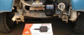
Replacing UAZ 469 brakes, UAZ 469 brakes, 31512, 31514, 31519
Task: replace drum brakes with disc brakes on the UAZ 469 and eliminate the squeaking noise when braking.
Progress of work on replacing brakes on UAZ 469
Preparing calipers for installation
I cleaned it, painted it with thermal paint, and installed a new repair kit.
Dries quickly, but according to the instructions you need to heat it up for full effect.
The complexity of the process is “3” if you prepare well beforehand and, as always, you won’t be able to do it without an angle grinder.
We remove everything unnecessary
The first to be the plan washer (the back wall was smeared with sealant)
We place a special ring inside the trunnion
We put on the trunnion
Screw on the oil deflector
We change the military hub, repressing the bearings and installing the Kortek oil seal
oil seal marking
Next is the drive from 3160
Next, we install the bracket and begin to try on the caliper. The fact that it won't fit is a fact. You will have to remove both from the caliper itself and from the final drive.
Achieving free movement of the caliper
We make an adapter for the Volga hose for UAZ or VAZ 21021
We tighten the hub nuts and install the clutch
A bit of a rut
Result: disc brakes are installed on the UAZ 469.
https://www.drive2.ru/l/6397395/
next article:
Symptoms of a problem
You can determine that you need to replace the pads without removing the wheels based on several signs:
- when braking, the car pulls to the left or to the right;
- the disgusting sound of metal rubbing against metal;
- creaking when braking;
- The drum and wheel disk heat up.
Friction against metal is, of course, a very bad situation. Pads or linings need to be replaced when they are worn out, when the rivets are recessed into the lining by less than 0.5 mm and the friction material is damaged.
When the drum with the wheel disk heats up significantly, this may also be due to a faulty pad. For example, the tension spring burst, the lining came off and jammed, but more often it is due to other reasons. An article about such heating is here.
To monitor brake wear, there are holes in the shield.
UAZ-469 car - characteristics, design, repair
Possible options:
- Controls of UAZ-469
- Preparing for work UAZ-469
- Engine mount UAZ-469
- Crank mechanism of the UAZ-469 engine
- Gas distribution mechanism of the UAZ-469 engine
- Lubrication system UAZ-469
- Engine crankcase ventilation system UAZ-469
- Gas exhaust system of the UAZ-469 engine
- UAZ-469 engine cooling system
- Preheater for UAZ-469 engine
- UAZ-469 engine malfunctions
- UAZ-469 frame
- Steering of UAZ-469
- Electrics UAZ-469
- Generator UAZ-469
- Voltage regulator PP132
- Battery UAZ-469
- Starter UAZ-469
- Control and measuring instruments UAZ-469
- Tools and accessories UAZ-469
- Marking UAZ-469
- Lubricants UAZ-469 and UAZ-469B
Utility vehicles UAZ-3741, UAZ-3962, UAZ-3909, UAZ-2206, UAZ-3303 are equipped with working, parking and spare brake systems. A service brake system with drum brake mechanisms on the front and rear wheels, with two separate hydraulic drive circuits to them from a two-chamber master cylinder: one to the brake mechanisms of the front wheels, the other to the brake mechanisms of the rear wheels.
The parking brake system with a drum brake mechanism located behind the transfer case and acting on the rear driveshaft has a manual mechanical drive. The spare brake system consists of each of the hydraulic drive circuits.
Installation of the service brake system of UAZ-3741, UAZ-3962, UAZ-3909, UAZ-2206, UAZ-3303, installation of front and rear brakes.
The front service brakes have two wheel cylinders, each of which acts separately on the pad. Cylinder diameter 32 mm. The rear brakes have one wheel cylinder acting on both pads. Cylinder diameter 25 mm.
Front wheel braking system.
Two wheel cylinders are secured to the brake shield using support pins and nuts. The support pins have eccentrics on which brass pad support bushings are installed. By turning the support pins with eccentrics, you can move the support ends of the pads relative to the brake shield. They adjust the brakes using support pins when assembling them at the factory or when repairing brakes with replacing pads or linings.
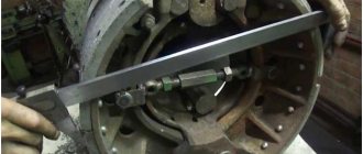
When correctly installing the pads with unworn linings and the brake drum, the “a” marks on the support pins (cores on the outer ends) should be located as shown in the figure above, or with deviations from this position in one direction or another up to 50 degrees. The friction linings of the pads are attached to the rim with aluminum rivets recessed into the body of the lining.
The moving ends of the brake pads fit into the grooves of the piston tips of the wheel cylinders. The pads, with the inner surface of their rims, rest on adjusting eccentrics, movably mounted on the brake shield. The eccentrics are kept from arbitrary rotation by strong springs. The pads are pressed against the eccentrics by tension springs.
The hexagonal heads of the adjusting eccentric axes are located on the outside of the brake shield. Using eccentrics, the required gap is established between the pads and the drum. The pads are kept from lateral displacement by the ends of the axes of the adjusting eccentrics and by springs installed in the middle part of the pads.
Inside each wheel cylinder there is a piston with two rubber O-rings and a spring that presses the wheel cylinder piston against the thrust end of the pad rib. The wheel cylinder has two holes. One hole is used to supply brake fluid from the hydraulic drive system, and the other is to release air from the system during bleeding.
It is closed by a bypass valve, which in the closed position ensures a tight seal. To prevent clogging, the valve opening is closed with a protective cap. The internal cavities of the wheel cylinders are protected from moisture, dust and dirt by rubber caps.
Rear wheel braking system.
In the lower part of the brake shield there are support pins, which are fitted with brass bushings similar to those of the front brakes, against which the pads swing. When correctly installing the pads with new linings and drums, the “a” marks on the supporting pins (cores on the outer ends) should be located as shown in the figure below, or with deviations from this position in one direction or another up to 50 degrees.
The rear brake pad lining is shorter than the front brake pad lining. This is designed to ensure that the wear on the rear and front pads is equal. Brake drums are the same on all wheels of the car. The drums are attached to the hub with three screws, which are unevenly spaced around the circumference.
This ensures that the drum is installed on the hub in one specific position, in which the drum assembly with the hub is processed. It is not recommended to move brake drums from one hub to another, as this will lead to increased runout of the working surfaces of the brake drum.
Hydraulic drive of the service brake system of UAZ-3741, UAZ-3962, UAZ-3909, UAZ-2206, UAZ-3303, device.
Consists of a suspended pedal, a vacuum booster, a two-chamber master cylinder, pipelines with connecting fittings and wheel working cylinders. The hydraulic drive pedal to the wheel brake mechanisms, as well as the clutch release pedal, swings on an axle on a plastic bushing, requiring no lubrication during operation.
The axis is fixedly fixed in the bracket. The return spring constantly holds the pedal in its original position by pressing it against the brake light switch cap mounted on the pedal bracket. The brake pedal is connected through a system of shafts and rods to the pusher of the vacuum booster.
Vacuum booster of the service brake system.
Serves to increase the efficiency of hydraulic brakes when the engine is running. If the amplifier fails, only the force from the driver's foot is transmitted to the pistons of the master cylinder through the brake pedal, pushrod, control valve, buffer and rod. The vacuum booster does not require adjustments.
Maintenance consists of checking the reliability of fastening, washing or replacing the amplifier air filter during seasonal maintenance before the winter operating season.
Service brake system pressure regulator.
Automatically adjusts the brake fluid pressure in the rear wheel brake circuit depending on the load on the vehicle, preventing the vehicle from skidding due to the rear wheels locking during heavy braking. It may not be installed on some modifications of UAZ-3741, UAZ-3962, UAZ-3909, UAZ-2206, UAZ-3303 vehicles.
Double-chamber master cylinder of the service brake system.
Serves to simultaneously create pressure in both circuits of the hydraulic brake drive when pressing the brake pedal. The master cylinder chambers are supplied with brake fluid from a reservoir mounted on the cylinder body. Each of the pistons has its own return spring. The relative position of the pistons is limited by a limiter sleeve and a screw.
Sources used:
- https://avtoremontnikam.ru/hodovaya/zamena-tormoznogo-cilindra-uaz.html
- https://pulyaet.ru/remont/tormoznaya-sistema-uaz-452-buhanka
- https://7gear.ru/avtomobili/glavnyj-tormoznoj-cilindr-uaz.html
- https://auto.kombat.com.ua/rabochaya-tormoznaya-sistema-uaz3741-3962-3909-2206-3303-pered-zadn-tormoza-gidroprivod-torm/
Replacing front pads on a UAZ
Before starting replacement work, to comply with safety regulations, put the car on the handbrake and place chocks under the wheels. Further:
- loosen the nuts, jack up the car and unscrew the nuts completely and remove the wheel;
- turning the adjusting eccentric with a key of 17, bring the pads together;
- unscrew and remove the drum;
- remove the pressure springs with cups;
- remove the tension spring;
- Using a 19mm wrench, unscrew the support pin nuts and remove them.
Replacing the front pads of a UAZ
This completes the disassembly, but before replacing, do several operations:
- Check the integrity of the protective caps.
- Place a little grease under the protective cap; this will prevent rust from forming inside the cylinder.
- Grind down the bead on the drum. Check the inner diameter of the drum, its maximum value is 281 mm.
Assembly proceeds in reverse order, but there are several nuances:
- Not everyone has special pliers to install the tension spring. I do it this way: I make a ring with a piece of wire and hook it onto the spring. I pull it out and use pliers to guide it into the seat.
- The support bolt marks work for new pads and drum. In practice, after replacement, you will have to adjust.
- Do not install the wheel until the pad clearances have been adjusted.
After replacement, press the pedal 2-3 times to return the brakes to working condition. Periodically, to maintain the gap between the pads and the drum, it must be adjusted manually.