Some time ago, I noticed that the clutch began to slip and literally a week after that the loaf almost stopped moving, it started with great difficulty, and did not accelerate beyond 70. And then I decided to change the clutch. No sooner said than done.
On Saturday morning I quickly removed the universal joints, rods, etc. First I removed the steering gear, then the gearbox,
I went to the store and bought a new Weber disk.
The next day, Sunday, I started putting it back together and installed the clutch (it’s not difficult - the kit included a thing for centering the disc). I brought together the Republic of Kazakhstan and the checkpoint. The book said check how the gears are engaged after assembly, but I didn’t do this, and as it turned out, it was in vain.
Then he began to install the gearbox and control valve in place. I lifted the gearbox and the steering wheel using belts with ratchets that secure the load; the rest is impossible to describe.
It turned out that the recipe for installing a gearbox is simple - “you climb under the car, curse loudly for three hours and the gearbox is in place.” I screwed on the gearbox and supports, and that was the end of Sunday.
Then during the week I collected the rest, filled in the oil and everything seemed to be...
Changed gears - everything was fine. I started the engine - the gears did not shift... and the downshift did not shift... The next day, I replaced the fluid in the clutch system, adjusted the free play of the clutch pedal. After this, the gears began to engage with the engine turned on. “Well, finally, everything is fine,” I thought. I threw all my things into the back and started driving. And then it turned out that the loaf only moves in low gear, neutral is not switched on in the RK.
The next day (it was Saturday again), in the evening, I quickly removed the steering gear and it turned out that when I was assembling the steering gear and gearbox, the gear for engaging direct and low gear fell out of the fork... I adjusted the fork, turned on the direct gear on the steering gear, then the gear was pressed with the fork and did not dangle. And he began to install the RK in place. It took about 3 hours, I couldn’t get the shift rod into the hole in the bracket for a long time, I had to unscrew the support. Before installation, I changed the gasket and applied sealant. After 3 hours the RK was installed. The rest is just trifles. On Saturday night we managed to start moving. Replacing the clutch took more than a week... (our motto is “dementia and courage”)
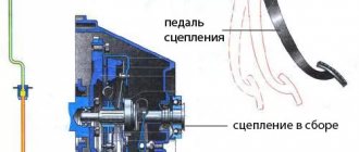
The clutch serves to briefly disconnect the engine shaft from the gearbox when changing gears and smoothly attach it when moving away.
UAZ loaf cars or officially UAZ-452 are equipped by the manufacturer with a dry mechanism with one disk. This device has a torsional vibration damper.
The device ensures the transmission of torque from the power unit to the transmission with a force of 17 kg/cm.
Legendary UAZ Loaf
The seemingly unprepossessing, primitive UAZ loaf , which is also called the UAZ tablet , UAZ tadpole , is capable of great “feats”.
The car feels great on bad roads or completely off-road. Many car enthusiasts will prefer more comfortable and expensive versions of minibuses to the UAZ, including well-known foreign cars such as the Mercedes Sprinter, Volkswagen LT or Ford Transit. Descriptions of the UAZ loaf model
History of the UAZ Bukhanka model
These cars look more presentable, have superior dynamics and speed characteristics, and are easy to operate and maintain. However, you can be 100% sure that the owners of such equipment will never drive their “iron horse” through mud and water, and it is unlikely that these cars will be able to get out of there “without losses.”
UAZ Bukhanka models
The only thing that is not encouraging is the fact that the car is still equipped with outdated units and systems, which makes their owners “suffer”. The level of equipment of the new UAZ Bukhanka remains the same as many years ago. Global automakers have long been installing modern braking systems and electronic engine control systems on their cars. On a domestic UAZ, the UED system only causes trouble, since if it breaks down it requires special repairs, accessible only to specialists. Because of this, the practicality factor of the car is significantly reduced. Craftsmen in most cases are engaged in re-equipment of UAZ Bukhanka to improve technical characteristics.
Tuning a UAZ Bukhanka car It’s also surprising how the manufacturer neglects modern trends. Many specialized Internet sites offer quite interesting tuning and modernization options, developed by ordinary car enthusiasts or tuning bureaus. It would be very helpful if these models were used immediately in factory production.
Advice for future owners Of course, the cost of a car equipped with additional equipment may increase. But you can install those accessories that will bring great benefits during operation, and at the same time will not require significant capital investments from the plant. In particular, this applies to body kits, bumpers, and heating systems.
Manual
True, considering how far foreign competitors have gone from our UAZ in price, you can not even pay attention to the increase in the cost of a fully equipped Loaf. By thinking about this, company managers could significantly improve the image of their products among the public, even at a slightly higher cost. This would make it possible to finally convince the buyer that the domestic automobile industry has begun to slowly move away from Soviet traditions.
Clutch functions
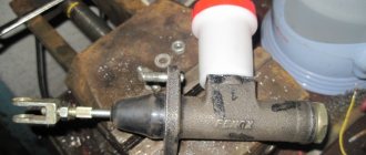
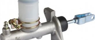
By pressing the pedal, the driver acts on the fluid in the line. The fluid transfers pressure from the master cylinder piston to the slave cylinder piston. The working cylinder moves the shutdown fork with its rod.
Together with it, the release bearing is pressed, transmitting force to the clutch mechanism, which disconnects the transmission from the power unit.
By releasing the pedal, the driver returns the entire mechanism to its original state. Under the influence of the return springs, all parts involved in the process of squeezing the clutch take their normal position.
UAZ 2206 Uazka › Logbook › Removing and replacing manual transmission
At home I quickly unscrewed everything, fortunately there wasn’t much there, and removed the box into one, exactly as in the video:
I discovered that I had a dead release bearing, oil leaks from the shanks, from under the gearbox and manual gearbox connections, a dead gearbox bearing where the front driveshaft is screwed, and the reduced gearbox also came out under load.
I twisted the purchased used box, opened the manual transmission cover, the teeth were all intact, everything seemed to be moving. I found a completely dead bearing on it in the place where the drum with the brake pads is. It will be interesting to see her in action, whether she is alive or dead, as I put it, we will see.
I didn’t have time to take a photo because... repaired one and was in a hurry. In the near future it will also be assembled into one. With God's help, I'm thinking of rebuilding the manual transmission, which is 76 kg.
Clutch functions
By pressing the pedal, the driver acts on the fluid in the line. The fluid transfers pressure from the master cylinder piston to the slave cylinder piston. The working cylinder moves the shutdown fork with its rod.
Together with it, the release bearing is pressed, transmitting force to the clutch mechanism, which disconnects the transmission from the power unit.
By releasing the pedal, the driver returns the entire mechanism to its original state. Under the influence of the return springs, all parts involved in the process of squeezing the clutch take their normal position.
Briefly about the design of the unit on the car
The Patriot has a single-plate dry clutch with a hydraulic drive. The operating principle of the unit is based on the transmission of torque from the engine flywheel to the input shaft of the gearbox due to friction.
The clutch mechanism consists of the following elements:
To separate the engine and manual transmission, it is necessary for the force from the driver’s foot to act on the release bearing, which will press the petals of the diaphragm spring and separate the discs.
For this purpose, a drive system is used, which consists of:
When you press the pedal, the force is transferred to the GCS piston, which displaces the hydraulics from the cavity and sends it through the tube to the RCS. The piston of the latter moves and with its rod acts on the release fork, which moves the release bearing and disengages the clutch.
Due to the production of friction material, the discs may not fit tightly together, and at high engine speeds an unpleasant odor will occur.
This contributes to rapid abrasion of the material and complete failure of the mechanism. In this case, it is necessary to replace the unit. And this involves dismantling the catalyst, gearbox and some other equipment.
Leveling up
After successful installation and assembly of the element, it is necessary to fill in new hydraulic fluid. The same one is used as for the brake system. After this, unscrew the air valve of the working cylinder several turns and press the clutch pedal 5-7 times. To avoid running to the salon several times, call an assistant who will bleed the system. Be careful - when you press the pedal, hydraulic fluid will flow out of the valve. Therefore, prepare the container first. This could be an ordinary mineral water bottle.
Removing air from the drive hydraulic system
Quite rarely, but it happens that the clutch needs bleeding. This can be understood from the fact that it does not turn off completely and the pedal is not pressed so softly. Bleeding is the removal of air from the hydraulic system. This process is carried out when the liquid in the tank is at a normal level.
During work, it is necessary to remove the rubber cap located on the bypass valve and install a hose in this place. Then the other end of the hose is lowered into a 0.5 liter container containing brake fluid in a ratio of 1:3.
Afterwards, the bypass valve must be turned one turn while another person presses the pedal all the way. You need to press the pedal until the air bubbles stop being released. The bypass valve must then be tightly closed.
Some UAZ owners may recommend tightening the bypass valve after each pedal press. This will help to significantly increase the pumping speed and achieve complete neutralization of air. Usually the air disappears from the system after the third or fourth repetition of the operation.
UAZ cars are very reliable. It doesn't take much effort to fix clutch related problems. You can carry out all the work yourself or contact a technical service. Clutch repair or adjustment is not an expensive service. As the owner of one of the UAZ series of cars, you need to carry out timely and constant care of the car, since an unscrupulous attitude can lead to severe pollution and lead to a number of difficult-to-solve problems.
Signs of trouble
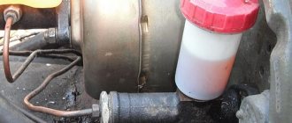
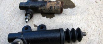
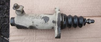
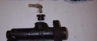
How do you know if your car needs to replace the clutch slave cylinder? UAZ is a very reliable car, but this part can also fail. A breakdown can be determined by several signs. Firstly, this is a sharp decrease in the liquid level in the tank. If there is a leak, the cylinder boot may have broken through. Damage may also affect rubber or aluminum tubes. Check their integrity. Secondly, the pedal stroke becomes softer. “Clutch failures” are observed. This indicates the presence of air in the system.
Repair
The presence of a diagram of the internal structure of the structure allows you to carry out independent repairs in case of simple malfunctions. Increased fuel and oil consumption, coolant leakage, uncharacteristic noises and knocking in the mechanism are the first indications for repair. Maintenance and replacement of worn-out components helps prolong the functioning of parts and vehicles.
How to adjust the clutch pads
In order to adjust the clutch on a UAZ, you will need to carry out the following repair work:
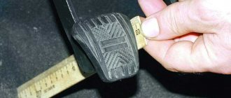
Adjustment of the free play of the clutch pedal is required if the distance between the rotating part located on the release levers and the adjusting screws and elements of the device does not lie within the range of 50.75-52.25 mm. The screws can be removed and put back in until the correct size is established.
The diaphragm spring connection does not require free play adjustment and does not require adjustment of the mechanism release system. The correct dimensions of the gaps and strokes are ensured by the design features.
How to bleed the clutch
Bleeding the hydraulic drive will be required if the pedal is pressed too softly and it is not possible to completely turn off the mechanism. All this indicates the presence of air in the hydraulic drive unit. Repair measures are carried out through the bypass valve in the same way as work with a hydraulic brake drive. Having an assistant will make the task easier. Sequencing:
Air will escape from the system into the container with liquid. When the movement of bubbles stops, you need to press the pedal and turn the valve all the way. During activities, the presence of the mixture in the master cylinder tank should be constantly monitored to avoid re-entry of air into the system.
The described procedures are performed several times until the bubbles completely disappear.
After pumping, add liquid to the tank and return the protective cap to the valve. Do not use liquid from the container into which the hose was placed for this purpose. It contains air that disappears on its own after 24 hours or after filtration.
Read more: Car door seals
How to install the clutch disc correctly
The functionality of the vehicle, smooth movement, absence of noise and vibration, and comfortable movement along the highway depend on the correct installation of the part. Sequence of actions on how to correctly install the clutch disc:
One of the clutch disc surfaces protrudes more than the other. This side should be facing the gearbox. Installation of elements is carried out in reverse order. To adjust the disks, you will need a special mandrel. After completing the work, it is better to apply lubricant to the splined end of the main shaft.
How to change the clutch
The clutch is a means of disconnecting the engine shaft from the gearbox for a short period during a gear change, a method of smooth transition when starting and starting to move.
The UAZ 452 clutch is distinguished by a dry mechanism and the presence of one disc with a torsional vibration damper. The system is characterized by the transmission of torque from the engine to the transmission with a coefficient of 17 kg/cm. During repairs, you can update the system and install a petal mechanism.
The first stage is preparatory work. To dismantle and subsequently install the structure, you will need the following materials and tools:
Clutch installation is carried out in the following sequence:
A special mandrel will help in assembling the clutch.
Before installing it, the disk and flywheel housing must be degreased. Install the driven disk on the mandrel and insert the resulting structure into the flywheel. Pre-lubricate all fasteners with thread locker. Tighten the bolts in several stages. After installation, you can remove the mandrel. The gearbox and transfer mechanism are mounted in the reverse order. Upon completion of the work, it is necessary to carry out measures to adjust the clutch pedal travel.
Traction is an important component of transportation. Timely replacement of old elements, regular diagnostics and monitoring of operation are the key to long service.
Communities › UAZ drivers › Forum › removing the box on Bukhanka
In general, share your experience, I plan to remove the transfer case and transfer case separately, but I think I heard that it’s hard to install them later, they say you need to do it together, how hard is the work and what pitfalls are there?
full of crap. worked on a loaf for 1.5 years, the car is great if not in repair. if you remove it separately, you will have more problems for two hours. but in one place it’s a hard ass.
Yes, and it’s a little difficult to climb under it to separate the transfer case from the box. Words can’t describe it; you have to try it. Just mats.
I cut a special hatch in the floor, now I can remove it and install it normally using a hand winch.
can you post pictures of what kind of hatch I didn’t see in your BZ or describe the process
I didn’t take a photo, and even now there’s a seat above it. Briefly about the process. I found a hatch, well, which we have above the tanks. I removed the gearbox from the RK, and there you will see on the cross member, well, where the airbags are still attached, there is a square hole in the middle. I drilled 4 holes from the bottom with a screwdriver so that I could see the boundaries. I measured the dimensions of the hatch, drew a square on the floor, leaving drilled holes inside the square, and cut it out with a grinder. All. I fasten the hatch with screws for metal, and I attach the winch to the roof of the car through a corner, there is just a fastener for a stretcher, and I screw the corner into its place while I’m working.
I understand, I think I’ll also think about something
I’ve been driving my UAZ since 1996. When I was younger, I took off the box with the drawer from the bottom one and put one on. But now I’m almost 57 years old, I took it off from the bottom, but I can’t put it on anymore, I groaned, groaned, spat on everything , not sparing the floor, I carefully made a window in the floor, having first removed the Lenolium and plywood on the floor. I cut out the window with a grinder. I made a small winch and installed it easily with the winch.
I recently removed and installed it, it’s completely more convenient. You remove all the rods, unscrew the bolts, put the Zhiguli tank on it and drop it on it. It’s also better to install everything together, drill a 12 mm hole in the floor, there is a square technological hole in the center between the frames below, it exactly coincides with the center of the box and transfer case. In the cabin, you place a pipe on the bars, mine is 32 mm, and weld a handle to it so that you can turn it just so it doesn’t touch the floor. You tighten the cable with a noose between the box and the transfer case, thread it through the hole, wind it around the pipe and calmly swan. The child doesn’t have to put any effort into lifting it up, but you calmly stick the slots in from below, catch it by turning on the gear, and that’s all. Installed in a couple of hours.
I want to completely seal the floor, maybe I can make some kind of lift to lift the entire box
You can build something like a small car from an old jack, weld a fork and a frame on wheels like a rolling jack. There are plenty of options.
Yes yes I was thinking about something like that
I filmed almost the same way only without the block - it’s just that in the cross member on which the gearbox hangs, apparently the previous owner cut a window into it and let an old rag tow halyard through.
I've already seen this somewhere, BUT if necessary, everything goes haywire, you're not going to shoot every day, so I think there's no point in fussing
Read here how a person installed the gearbox and the gearbox assembly - uaz-glafira.indeep.ru/node/1013, you can remove it using the same principle. You can also remove it separately, but it will take longer; you can also install it separately, but again it will take longer and the gasket at the joints of the gearbox, control gear and “helicopter” may not fit well (after all, it is quite problematic to control how well it fits) and for this reason oil will drip at the joint (this happened to me when I installed it separately). Using the method described above, I recently removed the gearbox and control gear assembly alone, with minimal effort. Or as an option - www.drive2.ru/cars/uaz/33…/288230376152090269/#post
I liked the option with rollers, now I’ve just removed the floor, it’s time to weld the rollers
I took it off in the fall: I unscrewed the transfer case from the box and removed it; there was no need to work with the cardans and the navel for an hour. Look carefully at where in the plate there is a window for the transfer case levers (one lever (which is closer to the box, you need to move forward, and the second one should be pushed into the transfer case so that the levers are inline!). Everything goes in and out great, without outside help. In the future, you can have a bigger window do.
This is all good, but when I pulled out the engine with the gearbox, they dropped down in the transfer case, is that very bad?
How it went down in more detail.
This is my first time removing an engine. and decided to remove it with the box because it’s hard to unscrew the box from the bell in 3151... well, I separated the transfer case from the box while they were also pulling and unscrewed the transfer case support from the steering wheel... when they pulled out the box with the engine. I looked into the transfer case and there the gears in it were lowered below the center and fell through to the bottom... I’m thinking maybe they broke something while they were pulling the engine... for example, with the shank of the box they tore off a thread in the transfer case, and now I’m going through this for the second day.
No, I don’t think it dropped, probably because the shaft went away, I’m not an expert on boxes, create a separate topic on your issue with photos, maybe someone more experienced can tell you.
Well, yes. In principle, I looked at the photos, there’s nothing to worry about... the gear selection paw and the cardan at the back are on a bearing... as if the bearing would not be torn out. Although the cardan is straight
REMOVAL, REPAIR AND INSTALLATION OF PEDAL ASSEMBLY
REMOVAL, REPAIR AND INSTALLATION OF PEDAL ASSEMBLY
The pedal assembly is a collapsible structure that combines the clutch, brake and throttle pedals on a common bracket. If the pedals squeak or jam, or if the pedal return springs break, remove the pedal assembly to lubricate the rubbing surfaces or replace parts.
You will need: all the tools necessary to remove the steering column, as well as a “13” wrench, pliers, a bit, and a hammer.
If you are removing the pedal assembly to replace it, remove the brake light switch from it (see “Replacing the Brake Light Switch”).
3. Disconnect the brake booster pusher fork from the brake pedal (see “Replacing the brake booster”).
4. Unscrew the three nuts that simultaneously attach the vacuum brake booster and the pedal assembly bracket to the front panel, and one nut of the left side fastening of the bracket.
6. Disconnect the cables from the throttle pedal (see “Adjusting and replacing the throttle cable”).
8. Unscrew the two nuts of the lower fastening of the pedal assembly bracket to the front panel.
10. To remove the clutch and brake pedals, pry them up with a screwdriver.
12. Remove the clutch pedal from the axle.
15. Remove the pedal axle and remove the brake pedal from the bracket.
18. Remove the clutch pedal servomechanism retainer.
20. Remove the servo guide clamp.
Remove the throttle pedal only if absolutely necessary, since its axis is additionally fixed in the bracket by welding.
22. If you need to remove the throttle drive pedal, remove the weld seam using any available method (see note above) by prying it off with a screwdriver.
24. If it is necessary to replace the plastic pedal bushings, press them out of the pedal lugs using a mandrel of a suitable diameter (for example, a socket from a tool kit). Press in the new bushings in reverse order.
25. Reassemble the pedal assembly by replacing:
– worn or damaged spacer bushings;
– pedal return springs that have lost their elasticity or are broken;
. and a heavily compressed servo spring.
UAZ 3303 Camel › Logbook › No pedals?! Part two. Clutch pedal
So, the ill-fated clutch pedal is already gone. I began to wonder what was here and how...
Where then do such requests come from: the pedal travel is 210 mm (taken from the instructions), in my case on the car it is 220 mm. Against theirs, foreign 140 mm?
To thoroughly understand what is here and how it works. I like this Russian trait: not to think about what, how and why it works there - it works! Then I decided to deal with this radically, calmly identify the causes, and figure out methods for eliminating them. Purely arbitrarily, the pedal height figure of 150 mm was chosen (any one could have been chosen, but this one is kind of average, beautiful). In addition, if possible, I will adjust the brake pedal to this number. And as usual, I didn’t want to turn the repair of one part into the repair of the entire machine and make any drastic changes to the design of the machine. Minimum costs and time for repairs.
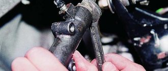
The pedal axis is secured to two plastic ball joints. The first one is closer to the pedal. By the way, you can see a homemade stop there, which I used to eliminate the generally prohibitive pedal travel. The movement of the pedal did not perform any useful work, and the rod did not even move. The second one is closer to the clutch cylinder. I didn’t remove the cylinder, I just removed the fork from the GCS rod. I knocked out the clutch pedal mounting pin, unscrewed the bushings, and then the axle and fork were quite easily removed from the car. Ah, this is where the problems started
I found a suitable sheet of paper. I made a life-size clutch pedal template. I drew a diagram of the operation, rotating the upper lever 180 degrees for convenience. Set the desired clutch pedal height. I calculated it so that with this smaller pedal stroke the piston stroke remained the same. So, I’ll leave the axle the same, but I’ll redo the upper arm. Plus, I bought a roller, a fork, and plastic bushings at the store. The result of the reflections pleased me - there is a prospect of meeting the given dimensions.
It could have been collected. But there was one more problem that I would like to solve at the same time. This is moving the clutch pedal to the right, closer to the steering column. In principle, you could simply move the ball joint to the other side and drill a new hole. It turned out to be about 30 mm, and there were no problems here
But I wanted more, to move the pedal significantly (by 70 mm). As a result of the torment, only 67 mm was achieved.
Principle of operation
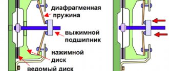
UAZ Patriot cars have the following type of clutch: single-disk with a centrally located diaphragm spring. By the type of friction it is dry, by the mode of activation it is constantly closed. Diaphragm clutch is also called petal clutch. This type is also used in other UAZ models: 3741 “loaf”, SUVs 469, 3151. Petal is also used for cars of other brands.
It consists of the following parts:
The pressure plate is housed in a stamped steel housing, bolted to the engine flywheel. The driven disk is clamped by a spring, it is located between the flywheel and the pressure plate. During operation, the closed type bearing does not require lubrication.
clutch release drive on UAZ Patriot vehicles Its composition:
The purpose of the drive is to transmit force from the pedal to the fork. When the pedal is applied, a piston located in the master cylinder moves and forces fluid through a pipeline into the slave cylinder. A piston placed in the slave cylinder acts on the clutch release fork. Then the fork moves the bearing along the guide. The bearing, in turn, acts on the diaphragm spring, which stops pressing the pressure plate against the flywheel. The clutch switches off.
Paddle clutch has the following advantages:
Clutch adjustment UAZ 469
Clutch control drive for UAZ-469 car
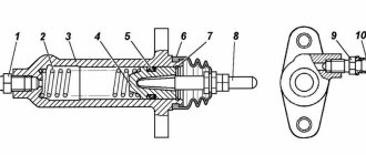
The drive (Fig. 53) is a system of levers and rods that connects the clutch release fork, coming out of the clutch housing, with the clutch pedal at the driver’s workplace.
Clutch pedal 1 is secured with a pin at the left end of pedal shaft 3.
With the clutch pedal on the shaft, brake pedal 2 is freely installed.
The upper position of the pedals is determined by the emphasis on the buffer on the inclined floor of the body.
To lubricate the pedal assembly, a grease fitting 5 is installed on the shaft.
The drive lever 4 is connected to the intermediate lever 8 using an adjustable rod 16.
The intermediate lever on the axle is locked with a spring ring and lubricated through a grease nipple. The smaller arm of the intermediate lever is connected to a pusher, which, with its spherical end, rests against the heel of the clutch release fork. Springs select gaps in the mechanism and hold its parts in the “clutch on” position.
Rice. 53. Clutch control drive: 1 — clutch pedal; 2 — brake pedal; 3 — pedal shaft; 4 - drive lever; 5 — grease fitting; 6 — pusher; 7 and 17 — tension springs, 6 — intermediate lever; 9 — clutch release fork; 10 — ball pin: 11 — pull lever; 12 — clutch release bearing; 13 - sealing coupling. 14 - buffer; 15 — intermediate lever bracket; 16 — adjustable draft; 18 — pin with a square head; 19 — free play adjustment nuts
Clutch maintenance consists of cleaning dirt, tightening bolted connections, adjusting and lubricating in accordance with the lubrication table. After driving on muddy roads, clean the hole in the bottom of the clutch housing. Lubricate the clutch release bearing in a timely manner through the grease cap located on the right side of the clutch housing.
Adjust the clutch mechanism with the clutch pressure plate removed in the following sequence:
1. Install a driven disk template in the form of a 9.5 mm thick ring between the plate and the pressure plate. Secure the assembled pressure plate to the housing with six bolts.
2. Adjust by screwing and unscrewing the adjusting bolts until the size is 51.5 ± ±0.75 mm - the distance of the bolt heads from the surface of the plate (Fig. 54). The difference in distance from the plate to the bolt heads should not exceed 0.2 mm.
3. After adjustment, lock the lever bolts by bending the edge of the lever into the groove of the bolt shank, as shown in Fig. 55.
Maintenance of the clutch control drive is reduced to adjustment and periodic lubrication of friction units through two grease fittings. The frequency and type of lubricant must correspond to the instructions in the lubrication table.
Source
Step-by-step instruction
The hydraulic lifting mechanism that the UAZ will be equipped with consists of several components: a semi-frame, a subframe, an electrically driven hydraulic pump, a hydraulic crane, an oil tank, a hydraulic cylinder and high-pressure oil lines.
Half frame, subframe, hydraulic cylinder
Let's start with the half frame, it is needed to install the body. It is this that allows the body to tip over.
The half-frame consists of two parts. One part is rigidly fixed to the UAZ frame. By means of pin hinges on one side it is connected to the second part, to which the loading platform is attached.
It is better to make the longitudinal beams of both half-frames from T-beams and I-beams, and position them so that the upper part of the folded beams rests on the beams of the lower part of the half-frame.
The lower part of the semi-frame is strengthened with cross members. The top one, in addition to the crossbars, should also have transverse projections on the sides, which will provide support for the cargo platform along its entire width.
At the end where the pin hinges will be located, lugs are attached to the parts of the semi-frames, which must match with their holes. The pins will need to be installed in these holes, and they will need to be secured in the holes to prevent them from falling out.
To connect the half-frame structure, you can use welded joints, but it is better to secure the lower part of the half-frame to the car frame using bolted connections.
The hydraulic cylinder is taken from a GAZ-53 car. Its length is quite enough to overturn the body of a UAZ. This cylinder has ball joints on both ends, so installation will require two ball joints under the cylinder. One of these supports is fixed to the cross member of the upper part of the half-frame.
The second ball joint is the lower one, fixed to the subframe. This subframe should be in the shape of a bracket. This shape is made so that the hydraulic cylinder, when folded, does not interfere with the complete lowering of the body and the landing of the upper part of the semi-frame on the lower part. The dimensions and method of fastening the hydraulic cylinder subframe are selected experimentally. After this, the hydraulic cylinder is installed in place.
Hydraulic pump, its drive and control valve
Next we move on to the hydraulic pump and its drive.
Most often, the pump is NSh-10, from MTZ-80. Its performance is quite sufficient for the operation of a hydraulic cylinder. There are several pump drives, so we will describe the simplest one, namely from the starter. To do this, a starter from MTZ-80 is taken and slightly modified to allow operation for a long time. Next you need to connect the starter shaft to the pump shaft. To do this, you can use the hinge from the steering of any passenger car. Next, the starter and pump are fixed on the platform to prevent them from moving relative to each other.
The pump and drive are fixed to the cross member of the car frame, so as to prevent their damage. Then the wiring is thrown from the car’s battery to the starter, making sure to include a switch in the circuit.
An oil tank is also attached to the frame of the car; a volume of 10 liters will be enough. Then the lines are connected from the oil tank to the pump, and from it to the hydraulic cylinder.
A hydraulic valve is installed in the pipeline connection diagram behind the pump, which can be purchased at any agricultural spare parts store. technology. During lifting at one of the valve positions, it will allow oil to flow in one direction and prevent its return. After turning the tap, the oil will be able to move back.
Frequent malfunctions and their causes
The clutch system of a UAZ vehicle is characterized by various malfunctions: the clutch is strengthened, the mechanism does not disengage, slips or does not pump. Timely maintenance, replacement of worn parts, lubrication and monitoring of the liquid level in the tank, diagnostics of all systems and components of the mechanism help to avoid such problems.
The operating instructions provide basic information about the operation of transport units, their preparation for operation, the rules and frequency of monitoring the functionality of the units, the main malfunctions and the decoding of error codes. Following the manufacturer's recommendations will extend the life of the equipment. Simple breakdowns can be fixed yourself.
For more complex system malfunctions, it is recommended to contact a service center.
The first category of reasons relates to the problem when the system cannot start completely when the pedal is lowered. The algorithm of actions is as follows:
If the system starts up jerkily or with vibration, the reasons may be as follows:
If an extraneous noise occurs when you press the pedal, this may indicate that the bearing has become unusable or lacks lubrication. If using oil does not help, you will need to purchase a new element. A break in the release spring makes it impossible to lock the pedal in the upper position. The spring needs to be replaced.
Clutch disappears
Often the mechanism does not start or disappears after the vehicle has been idle for a long time. The probable cause is “sticking” of the driven disk to other structural elements. If several attempts to start the car do not lead to success, it is better to contact a service center. In this case, you will not be able to correct the situation on your own.
Drives the clutch
A common group of malfunctions is associated with a situation where the clutch is driven and there is no way to completely disengage the mechanism. There could be several reasons:
Increased clearances in the drive also indicate the need to replace worn components.
Carrying out replacement
Step-by-step replacement instructions:
- Place the UAZ loaf car on high supports made of bricks and wooden blocks. Avoid falling from supports.
- Drain the operating oil from the gearbox and gearbox.
- Unscrew the rear driveshaft from the drive shaft. Place tags. When reassembling, install exactly the same as it was. Otherwise vibrations will appear.
- For the convenience of further work, unscrew the rear cardan completely - from the rear axle too. Place tags. Unscrew the front driveshaft only from the drive shaft. Place tags.
- Remove the muffler.
Repair
The presence of a diagram of the internal structure of the structure allows you to carry out independent repairs in case of simple malfunctions. Increased fuel and oil consumption, coolant leakage, uncharacteristic noises and knocking in the mechanism are the first indications for repair. Maintenance and replacement of worn-out components helps prolong the functioning of parts and vehicles.
How to adjust the clutch pads
In order to adjust the clutch on a UAZ, you will need to carry out the following repair work:
Adjustment of the free play of the clutch pedal is required if the distance between the rotating part located on the release levers and the adjusting screws and elements of the device does not lie within the range of 50.75-52.25 mm. The screws can be removed and put back in until the correct size is established.
Measure the distance from the plate to the heads of each claw screw; it should not differ from each other by more than 0.2 millimeters. Tighten the adjusting screws to set the distance with the required difference. Fixation of each claw screw occurs by pushing the edges of the claws into the grooves of the screw shanks.
The diaphragm spring connection does not require free play adjustment and does not require adjustment of the mechanism release system. The correct dimensions of the gaps and strokes are ensured by the design features.
Clutch adjustment on the UAZ “Bukhanka”
“Loaf” is what the common people call van-type UAZs of the 452 model series, which were produced from 1965 to 1979; as well as UAZ 2206/3741/3909/39094/3962/3303.
Let's consider one of the most popular cars of the Ulyanovsk brand today - UAZ 3303. It has versions 330394 and 330364, differing in that they are equipped with a more powerful injection engine ZMZ-409 with 112 hp; whereas the basic configuration of the flatbed truck is equipped with a ZMZ-417 4-cylinder gasoline engine with a power of 76 hp. and volume 2.445 liters.
The internal combustion engine of this “loaf” is equipped with a dry single-plate clutch, with a central diaphragm-type pressure spring with retractable tabs. For proper operation of the engine, you need to know how to engage the clutch on a UAZ 3303.
For clarity, we suggest that you familiarize yourself with the video of the Kolupaiev channel:
It is also worth noting that UAZ vehicles with a ZMZ-409 engine are equipped with a clutch pedal contact sensor, which is adjusted so that the gap between the buffer and the sensor rod is 0.5 millimeters.
Clutch adjustment UAZ 469
The old-style UAZ 469 is equipped with a spring-lever clutch mechanism. Setting the gap of the release levers is similar to setting the clutch of a UAZ 3303.
In order for the clutch system to work correctly, it is also necessary to ensure the required gap of 2.5-3.5 millimeters between the heads of the bolts of the tabs and the clutch release bearing. The full travel value for this SUV is set in the range from 14 to 16 millimeters.
How to bleed the clutch
Bleeding the hydraulic drive will be required if the pedal is pressed too softly and it is not possible to completely turn off the mechanism. All this indicates the presence of air in the hydraulic drive unit. Repair measures are carried out through the bypass valve in the same way as work with a hydraulic brake drive. Having an assistant will make the task easier. Sequencing:
Air will escape from the system into the container with liquid. When the movement of bubbles stops, you need to press the pedal and turn the valve all the way. During activities, the presence of the mixture in the master cylinder tank should be constantly monitored to avoid re-entry of air into the system.
The described procedures are performed several times until the bubbles completely disappear.
After pumping, add liquid to the tank and return the protective cap to the valve. Do not use liquid from the container into which the hose was placed for this purpose. It contains air that disappears on its own after 24 hours or after filtration.
How to install the clutch disc correctly
The functionality of the vehicle, smooth movement, absence of noise and vibration, and comfortable movement along the highway depend on the correct installation of the part. Sequence of actions on how to correctly install the clutch disc:
One of the clutch disc surfaces protrudes more than the other. This side should be facing the gearbox. Installation of elements is carried out in reverse order. To adjust the disks, you will need a special mandrel. After completing the work, it is better to apply lubricant to the splined end of the main shaft.