UAZ 3303 Ural rascal › Logbook › Hydraulics
Hi all!
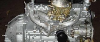
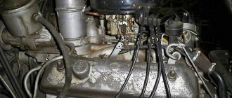
It all happened - I assembled full-fledged hydraulics for the tadpole. Everything is of a classic design: reservoir, pump, hydraulic distributor, cylinder. Everything works great! I'll write everything down in more detail. 1. Pump. Replaced the NSh-10 right rotation www.drive2.ru/l/4517398/. (I’ll get ahead of myself - the pump needs to be changed, because the one loaded with hot oil does not want to unload). It’s comfortable, I can screw on the hoses without any problems. Doesn't interfere with anything. I was most worried that the belt would slip; after all, the pulley on the drive is a B profile. But so far everything is ok. In principle, you can install a short crankshaft-pump belt, then the contact area of the belt will be the floor of the pulley, most likely I will do so.
2. Hydraulic distributor. In the stash there was a tractor hydraulic distributor R-80 with YuMZ-6l.
It has three sections. One for the dump truck, the other two will power the front and rear hydraulic winches (although they don’t exist yet, we’ll come up with them). Initially, I wanted to install the distributor in the cabin, on the tunnel between the gear shift knobs. But he assumed that if something happened, there would be a viper in the cabin in the form of splashed oil. And my ceiling is white...). Then I installed a hydraulic distributor in the tunnel on the cabin side member. To do this, I welded two sections of 20/20 square pipe onto the spar and secured the spreader.
Then I made a cut on top of the cabin and made a power handle from some kind of rod.
3. Tank. I decided earlier on where to mount the tank - on the cab, at the back. After a short search, a 12 liter round tank was found at a scrap metal collection point. I don’t know what unit it comes from. But inside it was a solarium. Didn't wash it much. I cut in a ball valve and welded a fitting for the return line.
4. Lifting cylinder. Initially I was looking for a double-sided cylinder to lift the body. I really wanted a forced lowering of the body. For this purpose, I found (at the same collection point) the working cylinder of the DT-75 blade, and in place with fasteners, which made it easier for me to install it. The cylinder stroke is one meter.
After several fittings (about 15 times), I made fastenings in the subframe and in the base of the body from 100 channels. The cylinder is tilted at 30 degrees.
Source
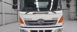
Dump truck installation for UAZ
UAZ-330365 (“Tadpole”) converted into a dump truck. UAZ-330365 Dump truck
The standard onboard platform and fastening elements were dismantled. A subframe with a dump body (two-way unloading) with hydraulic lifting equipment is installed on the chassis side members using standard fasteners. The subframe is secured to the car frame using stepladders.
The hydraulic distributor, power take-off box with hydraulic pump were installed in the place provided by the manufacturer, and the oil tank. Rear lights, battery, fuel tank, tail lights are installed and connected.
The vehicle complies with the requirements of clause 1.7 of Appendix No. 6 of TR CU 018/2011.
The maximum weight and its distribution along the axles and sides, as well as changes in the coordinates of the center of mass, do not exceed the limits established by the vehicle manufacturer.
The overall width does not exceed 2.55 m, and the height is 4.0 m.
The components and assemblies are securely fastened to the places provided by the design with elements similar in design, quantity and material to the fastening elements of the base car. Connections in the exhaust system, engine fuel supply, brake system, power steering system and power take-off with hydraulic pump are made using standard parts and structural elements (fittings, pipelines, hoses, etc.).
The dump body is securely fastened to the vehicle frame with fastening elements similar in design, quantity and material to the fastening elements of the body of the same vehicle, manufactured under mass production conditions, of the same or greater technically permissible maximum weight.
All wires are reliably protected and firmly attached to eliminate the possibility of breakage, chafing or wear. Every electrical circuit that powers any piece of equipment has a fuse or switch.
The driver's cabin is equipped with standard rear-view mirrors on both sides.
The vehicle complies with the requirements of clause 9 of Appendix 3 of TR CU 018/2011 regarding protection against splashing from under the wheels.
The location and installation of rear external lighting devices and rear state registration plate lighting devices comply with UNECE Regulation No. 48.
UAZ-330365 Dump body UAZ-330365 Dump body - tank for hydraulic fluid UAZ-330365 Hydraulic cylinder for driving the dump body UAZ-330365 Dump body in technological mode
Continuity of components and assemblies
During the years of planned economic management, the price of cars was set centrally. And in order to keep costs in line, the automaker was forced to unify parts - use the same components and assemblies on different models at once.
UAZ 3303 wiring diagram
For reference: all the world's leading automakers adhered to a similar scheme for unifying parts and assemblies. As a rule, a multi-purpose platform is first developed, and on its basis various car models with different designs and body shapes are produced.
In particular, the electronic components and all electrical wiring of the UAZ 3303 were used from the “452” model, a multi-purpose all-wheel drive vehicle that rolled off the factory assembly line in those years and was involved in cargo transportation throughout the country:
- Rechargeable battery brand 6ST-60EM;
- Alternating current generator G250-P2 with integrated voltage regulator PP132-A;
- Electric starter type ;42.3708;
- Ignition coil B116
- Distributor (ignition distributor 33.3706);
- Electronic (transistor) switch model 13.3734;
- Spark plugs type A11
For reference: Later modifications of the UAZ 3303 were equipped with new generation generators. This was due to the installation of the UMZ-4218 injection engine, which complies with EURO-2 environmental standards, as reported in the promotional video of those years.
See also the Ural motorcycle wiring diagram.
Regular paddle switch
On the model of the first years of production, the instrument panel from the UAZ 3741 model was installed with virtually no changes. Therefore, the circuits for connecting electronic systems remained the same.
Common instrument panel for models 3741 and 3303
To control lighting devices and turns, a conventional type steering column switch was used, which had fixed positions:
- The direction indicator had 3 positions - turn left, right and off;
- The warning lamp (in diagram No. 6) informed the driver about his mode;
- The headlight switch (low and high) had two modes - only low and only high. The enabled mode was displayed using a warning lamp (in diagram No. 8) inside the speedometer.
For reference: with the ignition off, and also while driving, pulling the light switch towards you activated the high beam lamp switching circuit.
Classic scheme of a modified UAZ 3303-6 with conventional controls
At the same time, the windshield wiper and washer controls (no. 23 in the instrument panel diagram) were located under the hazard warning switch button and had the following algorithm:
- The purifier was activated by rotating the handle;
- Pressing the handle (meaning recessing the rod in the axial direction) activated the washer.
See also the UAZ-469 wiring diagram.
Multifunction steering column switch
The modification of the car in 1993 received the index 3303-6. Among the changes made to the design of the car with an extended platform, special mention should be made of the multifunctional steering column switch, which significantly changed the interior wiring.
Original UAZ 3303 wiring diagram - modification with a new type of steering column switch
Its appearance is due to the new instrument panel, which the “three hundred and third” borrowed from the new UAZ 39094 model.
As a matter of fact, the algorithm for controlling the actuators has also changed:
- Control systems for wipers and windshield washers;
- Direction indicator control systems;
- Headlight control systems.
Original photo of the new instrument panel
The features of the new switches were:
- Combination of the direction indicator control lever and headlight control lever;
- Removal of wipers and windshield washers from the instrument panel to the control lever;
- Addition of previously unused non-locking modes for levers.
DIY dump truck UAZ-3303
UAZ-3303 is a small truck with good all-terrain qualities due to the presence of all-wheel drive. It has a frame structure, with a cabin installed on it, under which the engine is located, and two boxes - a transfer case and a gearbox. Behind the cabin there is a cargo hog platform that allows you to transport up to 1200 kg of payload.
This vehicle has become quite popular in agriculture, but its owners complain about the lack of equipment for dump unloading, since the manufacturer of this vehicle does not equip it with such equipment. Owners often do not agree with this decision of the plant and remake the UAZ-3303 with their own hands, creating a dump truck on its basis.
Those owners who have converted their cars indicate a significant increase in functionality and a decrease in the time for unloading the body from cargo. At the same time, the carrying capacity of the car itself does not decrease, since it is not very high anyway. But the installed lifting equipment makes the driver’s life easier, especially if the car is used to transport work loads.
Popular models
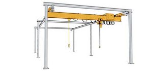
Loader cranes are produced in:
- Japan.
- China.
- Russia.
- Germany.
- Italy.
- Korea.
You can choose a power plant model from the following brands of leading global manufacturers:
- Atlas;
- Amco Veba;
- Effer;
- Hiab;
- Ferrari;
- Fassi;
- Palfinger epsilon;
- Unik;
- Isuzu;
- Foton;
- PM;
- XCMG;
- Atlant;
- BAKM;
- Velmash.
Foton units have a load capacity of 6 tons, and their length is more than 6 m. Foton Ollie transports goods and is useful in construction work.
The Isuzu QL 1100 TMA crane installation is one of the new products of the Japanese company. Load capacity - 5.5 tons, length about 6 m.
The Hiab 600EP5HiPro loader crane lifts loads up to 16 tons. It can be used to move large and oversized loads. Equipped with a remote control. This device is capable of lifting loads that are located near its wheels.
The mini crane moves loads weighing up to 3 tons. Popular models:
- SOROKIN 8.10.
- AE&T 1t T62201.
- AE&T 1t T62101.
- SOROKIN 8.6.
- SOROKIN8.2.
- SOROKIN 8.22.
- SOROKIN 8.3.
A suitable crane installation for Gazelle should lift a weight of 800 kg. These are the following models:
- RM 3622 CE, manufacturer - Italy, mounted behind the cabin;
- Unik URA - 100, manufacturer - Japan, mounted inside the on-board platform.
The Gazelle with CMU is suitable for transporting large and light cargo, as well as for loading and unloading operations.
Specifications
The UAZ Profi dump truck has a simple design and ease of operation. This transport is designed to work in any climatic conditions and on any terrain. All the main elements of the car are mounted on a welded support frame, which is made of high-strength steel. This unit can be repaired in the field; all components and mechanisms are easily accessible.
It has an 8-cylinder gasoline engine, manufactured in accordance with the international environmental standard Euro-1, and a manual 5-speed gearbox. Brakes are disc, dry, equipped with a mechanical drive.
Transmission ratios:
The gearbox is equipped with 2 cardan shafts, which are connected to the drive axles of the vehicle. The intermediate shaft is located between the manual transmission and the transfer case. The front and rear axles have a single bevel type final drive with spiral teeth.
Technical characteristics and indicators of the factory truck model:
How to make it yourself
In order to equip a UAZ with a dump truck, it is necessary to prepare drawings.
You can lay a square beam under the front side of the car, attach a long cable to it, which needs to be wound around the entire body part. To unload, you need to open the side of the vehicle, pull out the cable and attach it to some support, for example, a tree or pole. After this, you should start the engine and start moving forward. Moving along the body, the wooden beam will pull the load together.
Another method is to install a hydraulic lifting mechanism, which consists of a half-frame, a hydraulic pump element equipped with an electric drive, a hydraulic crane, an oil tank, a hydraulic cylinder, and high-pressure lines.
Step-by-step instructions for making dumping equipment:
Useful tips
It is recommended to secure one end of the semi-frame with pin hinges on the loading platform, this will help facilitate the operation of the installation. The top of the cross member should be equipped with cross bars to provide support for the entire perimeter of the loading platform.
To connect the semi-frame body to the car, it is necessary to use a welding machine for greater structural reliability.
The hydraulic cylinder can also be taken from the GAZ-53, because it is long enough to tip the body part, and the ends have ball-type tips.
The subframe should be made in the form of a bracket. This shape will allow the hydraulic cylindrical element, when folded, not to interfere with the body tipping over and the installation of the upper part of the semi-frame on the lower one. Parameters and fasteners must be selected experimentally.
After connecting the pumping element lines to the electrical circuit, it is recommended to install hydraulic crane equipment. When the body is raised, it will facilitate the flow of oil fluid in one direction. When the valve turns, the oil will flow back into the tank.
During installation and manufacture of a dump truck installation, safety precautions must be observed. The vehicle must stand on a flat surface, and the wheel mechanisms must be secured with special locking devices. The car needs to be put on handbrake. When making parts, you should wear a protective mask and goggles.
How to make a homemade crane in the back of a truck with your own hands - let's cover it step by step
A loader crane is a power unit mounted on moving platforms. She lifts and carries heavy loads in a short period of time. You can make such equipment yourself and install a homemade crane in the back of a truck.
Create an account
Register for an account. It's simple!
Register an account
Technical characteristics of the result
A sample with length/height/width parameters of 228/380/160 millimeters, respectively, will be considered. The weight of the finished product will be approximately 1 kilogram. A wired remote control is used for control. Estimated assembly time if you have experience is about 6-8 hours.
If it is not there, then it may take days, weeks, and with connivance even months for the manipulator arm to be assembled. In such cases, you should do it with your own hands only for your own interest. To move the components, commutator motors are used. With enough effort, you can make a device that will rotate 360 degrees.
Also, for ease of work, in addition to standard tools like a soldering iron and solder, you need to stock up on:
- Long nose pliers.
- Side cutters.
- Phillips screwdriver.
- 4 D type batteries.
The remote control can be implemented using buttons and a microcontroller. If you want to make remote wireless control, you will also need an action control element in the manipulator hand. As additions, only devices (capacitors, resistors, transistors) will be needed that will allow the circuit to be stabilized and a current of the required magnitude to be transmitted through it at the right times.
Small parts
To regulate the number of revolutions, you can use adapter wheels. They will make the movement of the manipulator hand smooth.
It is also necessary to ensure that the wires do not complicate its movement. It would be optimal to lay them inside the structure. You can do everything from the outside; this approach will save time, but can potentially lead to difficulties in moving individual components or the entire device. And now: how to make a manipulator?
Assembly in general
Now let's proceed directly to creating the manipulator arm. Let's start from the foundation. It is necessary to ensure that the device can be rotated in all directions. A good solution would be to place it on a disk platform, which is driven by a single motor. So that it can rotate in both directions, there are two options:
- Installation of two engines. Each of them will be responsible for turning in a specific direction. When one is working, the other is at rest.
- Installing one motor with a circuit that can make it spin in both directions.
Which of the proposed options to choose depends entirely on you. Next, the main structure is made. For comfortable work, two “joints” are needed. Attached to the platform, it must be able to tilt in different directions, which is achieved with the help of motors located at its base.
Another one or a pair should be placed at the elbow bend so that part of the grip can be moved along the horizontal and vertical lines of the coordinate system. Further, if you want to get maximum capabilities, you can install another motor at the wrist. Next is the most necessary, without which a manipulating hand is impossible.
You will have to make the capture device itself with your own hands. There are many implementation options here. You can give a tip on the two most popular:
- Only two fingers are used, which simultaneously compress and unclench the object to be grasped. It is the simplest implementation, which, however, usually cannot boast of significant load-carrying capacity.
- A prototype of a human hand is created. Here, one motor can be used for all fingers, with the help of which bending/extension will be carried out. But the design can be made more complex. So, you can connect a motor to each finger and control them separately.
Next, it remains to make a remote control, with the help of which the individual engines and the pace of their operation will be influenced. And you can start experimenting using a robotic manipulator you made yourself.
Popular models
Loader cranes are produced in:
- Japan.
- China.
- Russia.
- Germany.
- Italy.
- Korea.
You can choose a power plant model from the following brands of leading global manufacturers:
- Atlas;
- Amco Veba;
- Effer;
- Hiab;
- Ferrari;
- Fassi;
- Palfinger epsilon;
- Unik;
- Isuzu;
- Foton;
- XCMG;
- Atlant;
- BAKM;
- Velmash.
Foton units have a load capacity of 6 tons, and their length is more than 6 m. Foton Ollie transports goods and is useful in construction work.
The Isuzu QL 1100 TMA crane installation is one of the new products of the Japanese company. Load capacity - 5.5 tons, length about 6 m.
The Hiab 600EP5HiPro loader crane lifts loads up to 16 tons. It can be used to move large and oversized loads. Equipped with a remote control. This device is capable of lifting loads that are located near its wheels.
The mini crane moves loads weighing up to 3 tons. Popular models:
- SOROKIN 8.10.
- AE&T 1t T62201.
- AE&T 1t T62101.
- SOROKIN 8.6.
- SOROKIN8.2.
- SOROKIN 8.22.
- SOROKIN 8.3.
A suitable crane installation for Gazelle should lift a weight of 800 kg. These are the following models:
- RM 3622 CE, manufacturer - Italy, mounted behind the cabin;
- Unik URA - 100, manufacturer - Japan, mounted inside the on-board platform.
The Gazelle with CMU is suitable for transporting large and light cargo, as well as for loading and unloading operations.
How to make and install it yourself
You can install the truck crane yourself. It is installed on the vehicle. To do this, you need to remove the body from the chassis to change the subframe, because The factory design is weak and may crack. The subframe must be made with your own hands because attaching the crane installation directly to the frame is prohibited.
It can be welded from outer (18 mm) and inner channels. The planks are bent so that they follow the shape of the frame. The smaller rail is inserted into the larger channel to form a rectangle. Ready-made channels are attached to the welded frame. A fire hose is placed between them and the base to level the plane of the slats and frame.
The crane is installed on a subframe, which includes:
- beam;
- arrow;
- support posts;
- special stepladders.
The installation is secured using special stepladders. It is necessary to insert spacers into the stepladders, which can be made like this.
When many options for cranes mounted on the chassis of Gazelle trucks appeared, the owners of these vehicles began to think about how to install this mobile crane on their vehicle. After all, in the end you can get the most popular special equipment.
can have a load capacity from 1 to 11 tons.
The basis for attaching the CMU to the car frame is the subframe. You will have to do it yourself. It is prohibited to attach the manipulator directly to the frame.
Step-by-step instruction
The hydraulic lift required for upgrading a UAZ-3303 car with your own hands consists of a supporting semi-frame, a subframe, a hydraulic pump, a control valve, an oil tank, a hydraulic cylinder and an oil system.
Remaking the half frame, hydraulic cylinder and subframe
The semi-frame is necessary to fix the body and change its position. It consists of two parts: the first is firmly attached to the frame of the vehicle, the second to the loading platform. Pin hinges connect the elements to each other. In such a design, it is advisable to use I-beams or T-beams.
The top of the semi-frame is reinforced with a crossbar and side protrusions to support the body; only crossbars are installed at the bottom. At the locations of the pin hinges, special holes are made to ensure reliable fixation of the fasteners.
The half-frame base can also be held together by welding and bolting at the bottom.
DIY crane
Throughout the long history of its existence, man has more than once been faced with the task of lifting and moving heavy objects in space. For example, the familiar Egyptian pyramids consist of massive stone blocks that no one can lift. Therefore, one of the greatest achievements of mankind is the invention of the lifting crane, which made it possible to significantly simplify the task of moving heavy loads and speed up the construction of houses and other objects.
DIY crane
Machine structure
The operating principle of a crane is based on the physics of simple mechanisms. The simplest version of the crane is a stick placed on a fulcrum in such a way that the free ends have different lengths. Now if you hang a load on a short lever, it will take less effort to lift it. The most common design is one that uses, in addition to levers, a system of blocks.
A do-it-yourself crane is an indisputable assistant in small-scale construction. When constructing a private house, the use of bulky industrial cranes is not required. The height of the houses rarely exceeds 2 floors, and the weight of the lifted load is 200 kilograms.
Crane diagram
Although there are many variations of lifting mechanisms, a classic crane consists of the following parts:
- An arrow with a block attached to its end. Depending on its length, the height to which the load can be lifted is determined.
- Platform. The boom and counterweight are attached to it. It is the main part of the crane and is subject to significant loads. Therefore, when manufacturing a platform, it is important to pay special attention to its strength.
- Counterweight. Serves for crane stability. Defines the maximum load weight that the crane can lift. Stackable counterweight options are available to provide maximum stability.
- A guy wire connecting the boom and the counterweight. Allows you to adjust the tilt of the boom and move the load in both vertical and horizontal planes.
- Winch with cable. It is the lifting mechanism itself. The power of the winch determines how much weight the crane can lift.
- Stand with a rotating mechanism. It is necessary to turn the crane to the sides.
- The support cross, which is the base of the crane. Sets the stability of the entire structure. When manufacturing it, you should also pay attention to its strength.
terms of Use
To operate lifting mechanisms safely, certain rules must be followed.
Homemade Pioneer crane
These rules apply to any lifting device:
- The load capacity must not be exceeded. A load that is too heavy may damage the device.
- The base must be stable. Homemade lifting devices should be located on a previously prepared hard horizontal surface.
- In bad weather conditions, you should also refrain from working with the crane. Strong winds will throw the crane off balance, and poor visibility may make it difficult to see people under the boom.
- Before operating a crane or lifting device, it is necessary to conduct an external inspection to identify any malfunctions. If malfunctions are detected, operation of the crane is prohibited.
- It should be remembered that when working with the lift, you should not make sudden movements. The load must be lifted smoothly. And most importantly, do not stand under any lifted load.
What characteristics should a garage lift have?
In garage conditions, two types of lifting mechanisms are used. The first type includes a lift that can lift the entire car, and the second type includes a goose-type lift that allows you to move loads around the garage.
Lifts of the first type are stationary devices and the main requirement for them is stability. The car weighs more than a ton and should not have the slightest chance of falling. In order to prevent any accidents, the garage lift must have a reliable stopper.
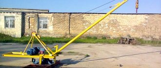
Homemade goose tap
The goose type lifts are most often used in auto repair shops. It is quite simple to make it from a profile pipe or channel. First, the base is welded on which the rotating mechanism needs to be installed. It is best to make an arrow with an adjustable reach. This will make it possible to move weights in any direction.
How a simple block design works
The pulley system or pulley system has been known to mankind since ancient times. The classic system design consists of pulleys and cable. One pulley is called a block. Depending on the method of fastening, the pulley can be movable or fixed:
- Fixed block. It is attached to the support and plays the role of changing the direction of movement of the rope. Does not provide any gain in strength.
- Movable block. It is located on the side of the load and gives a gain in strength.
The principle of operation of a pulley block is similar to the principle of operation of a lever in the physics of simple mechanisms. The role of the lever in this case is played by the cable itself. In the case of a simple block of two pulleys, the movable pulley divides the rope into 2 parts and in order to lift the load the same distance, a rope twice as long will be required. The work of lifting the load is performed in the same volume. And the effort, due to the fact that the length of the rope has become twice as long, becomes half as much.
If there are more than 2 pulleys in the system, the gain in strength is approximately equal to the number of blocks. In the case of 3 blocks, the effort will be 3 times less, and 4 blocks will require only a quarter of the original effort.
Complex block system how to calculate power gain
If the system is designed in such a way that one simple pulley pulls another simple pulley, then this is already a complex system of blocks. To theoretically calculate the gain in strength, it is necessary to conditionally divide a complex chain hoist into simple ones and multiply the values of the gain from simple chain hoists.
For example, if the system consists of 4 blocks, and the first conditional simple pulley has a gain of 3. It pulls the second simple two-block pulley, also with a gain of 3. The total force that will need to be applied will be 9 times less. It is the 4-block complex chain hoist that is most often used by rescuers.
Methods for attaching a rope to a lifting mechanism
When creating complex pulley blocks, there are often situations when a cable of the required length for attaching the moving block is not at hand.
Crane for gas blocks
Methods for attaching a cable using general-purpose rigging:
- Using a cord. Using a self-tightening knot, the cord is tied to the main cable. As the load is lifted, the grappling knot moves along the main rope, thereby allowing the height of the load to be increased.
- Using clamps. In the case of using a steel cable, it is not possible to use a cord, so it is necessary to use special clamps.
Principle of operation
During unloading, the driver must move the crane equipment to a position in which the oil fluid will flow in only one direction. After this, the power to the drive of the pumping mechanism is turned on, which takes part of the oil and transfers it under pressure to the body of the hydraulic cylinder.
When the body part is fully raised, the power to the hydraulic pump drive is turned off. The body will not be lowered thanks to the crane.
In order for the body to lower, the crane must be turned. After this, the oil fluid will begin to flow in the opposite direction, the pressure level in the hydraulic cylinder will begin to drop, and the loading platform, under the pressure of its own weight, will return to its original position.
Dump truck installation for UAZ
Gazelle dump truck
Conversion into a dump truck
The dump truck is fully equipped; you don’t need to purchase anything additional. For installation you will need a grinder and a welding machine.
We send dump trucks to other regions of the TC.
| Wheelbase | 2550 mm |
| Curb weight | 1845 kg |
| Maximum weight of transported cargo | 1225 kg |
| Total transport weight | 3070 kg |
| Ground clearance distance | 205 mm |
| Maximum ford depth | 500 mm |
| Permissible towbar weight | 850 kg |
| Fuel tank volume | 56 l |
| Power unit power | 90 l. With. |
| Engine displacement | 2.44 l |
| Diameter of cylindrical parts | 92 mm |
| Piston stroke | 92 mm |
| Compression ratio | 6,7 |
| Rated torque | 415 Nm |
| On-board voltage | 12 V |
| Track | On the front wheels - 1500 mm On the rear wheels - 1442 mm |
| Average gasoline consumption per 100 km | 12 l |
| Maximum engine speed | 2100 rpm |
| Tire size | 8,40-15 |
| Maximum tire pressure of front and rear wheels | 2.2 kgf/cm³ |
| Steering wheel play | 100 mm |
| Operating temperature | -40…+40°С |
| Brake drum diameter | 280 mm |
| Braking distance from a speed of 60 km/h | 5500 mm |
| Pad width | 50 mm |
| External turning radius | 4700 mm |
| car model | Load capacity | Rear unloading | Unloading on three sides |
| UAZ3303, KIA, BONGO, PICKUP, FARMER | up to 2 tons | RUB 87,300 | RUB 97,300 |
| GAZ3302 GAZelle, any foreign-made trucks | up to 3 tons | RUB 95,300 | RUB 105,300 |
| GAZ310, VALDAI any foreign-made trucks | up to 4 tons | RUB 145,200 | RUB 155,100 |
| Assistance in re-registration with the traffic police: | individually |
| Installation of a dump truck in Novosibirsk | |
| Load capacity up to 3 tons: | 20,000 rub. |
| Load capacity over 3 tons: | 30,000 rub. |
| Accessories | |
| Hydraulic cylinder made in China (rear unloading) | 15,000 rub. |
| Hydroelectric station made in China | 25,000 rub. |
Our company is engaged in the conversion of onboard vehicles of domestic and imported production with a carrying capacity of up to 4 tons into dump trucks.
Unfortunately, the domestic industry does not offer a large selection of light-duty dump trucks, and the price of imported vehicles is very high. The demand for the services of dump trucks of such carrying capacity is growing every year. This is due, first of all, to the development of low-rise construction in Russia, when many people go to live outside the city, and low-tonnage dump trucks are in demand for delivering coal, firewood, humus and other materials.
We offer to professionally and completely legally convert your flatbed vehicle into a dump truck. Work completion time : 7 days
– Low cost of conversion – Registration with the State Traffic Safety Inspectorate – Entering a market where there is no competition – Increasing your income – Increasing the value and liquidity of your car
Recommendations
Comments 12
What is the load capacity? Is COM standard or homemade? Is the PTO installed in the transfer case with NSh-10?
Sorry for the long silence - I was sick. Load capacity 1000 kg. The lump was specially developed (with forced lubrication). Placed on the distributor.
When driving, can you turn it off and then turn it on? Who is installed instead of the top cover of the transfer case?
The elevation angle is too small. What should you do if what you were transporting stuck to the body and won’t slide off?
Cylinder on ball joints Ф50mm. And this is more of a construction option. For peasants there is a slightly different model - with side unloading. For the distributor in the cabin, I can duplicate it with buttons (install an electric valve). But no one has canceled the FSA yet
Source
Popular manufacturing options
The UAZ-3303 truck has a two-seater solid metal cabin with two side single-leaf doors. In the front part of the structure, under the removable hood cover, the engine is located. Behind the cabin there is a cargo platform with folding sides. Depending on the model, it is made of wood or metal. The body can transport cargo weighing up to 1200 kg.
Dimensions of UAZ –3303
The technical characteristics of the car are designed for operation in different conditions, including in rural areas. Many people working in the agricultural sector note that despite all the advantages of the truck, it does not have equipment for unloading materials using a dump truck. However, it is possible to solve this problem if you construct a dump truck from an UAZ with your own hands.
Re-equipping a vehicle with a lifting mechanism will increase its functionality and save time on unloading the body. At the same time, the carrying capacity of the vehicle remains at the same level.
There are two options for making a dump truck convenient for use from a UAZ-3303.
Option #1
The easiest way is to lay a square beam under the front side of the body and attach a long cable to it, laid along the entire length of the platform. In this case, the truck will be unloaded as follows:
- When opening the side of the machine, the cable is pulled out and attached to some stable support, for example, a tree or pole.
- As the car moves forward, the beam moves along the body and pulls the load.
This method, although simple, is far from perfect, since the load may end up in an unstable position.
Device for installing springs - drawing
Option No. 2
When constructing a dump truck yourself, a more reliable way is to install the hydraulic system on the platform frame. Despite the fact that some companies offer ready-made kits for lifting the body, you can make such a device yourself.