How it works
The moisture separator device includes such elements as:
- Compressor. It is a mechanism that is used to increase the pressure level and compress the air flow. Made from aluminum. The outlet pressure should not exceed 0.82 kgf/cm².
- Radiator. Compressed air from the compressor part enters here. The mechanism is necessary to dissipate heat in the air. The radiator itself is equipped with an air-type cooling system.
- The body and the glass, which together make up the internal cavity of the structure.
- Deflector. This is an aerodynamic mechanism that is used to enhance the traction torque in a transport system.
- Filter element. Holds small dust particles. Some filters consist of o-rings to better retain dust and dirt particles.
- Damper. Necessary for separating a quiet zone from pollution.
- Valve and plug. With their help, accumulated contaminants in the interior of the air dryer are removed.
- Impeller. This is a rotating part equipped with blades. Necessary for twisting the air flow and throwing it onto the walls of the body and glass.
Air drying device for a compressor: DIY budget model
To make the paintwork smooth, uniform, and without defects, you can make an air dryer for a compressor at home with your own hands from scrap materials.
Method #1
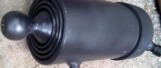
- A gas cylinder is used as a reservoir.
- It is cut in cross section with a grinder to create a collapsible structure.
- It will be operated in an inverted vertical position. In this case, the shut-off valve (faucet) is located below.
- In the upper part of the cylinder, an inlet pipe with threads at the ends is welded strictly horizontally, with a slight offset to one of the walls of the cylinder, using welding.
- This will allow the air entering under pressure to create rotating jets directly at the walls.
- The outlet piece of the tube is welded strictly in the center at the top of the cylinder. In this case, the length of the pipe is about 2/3 of the length of the tank.
- Turning waste (chips) is poured inside as a filter element.
- A strainer is installed at the outlet end.
Method #2
You can make a filter element to remove moisture from compressed air for high-quality painting of garage equipment according to the second option, using silica gel.
Necessary materials:
- a piece of pipe 0.65 - 0.7 m long and 100 mm cross-section.
- sheet metal (thickness 3 mm);
- metal grid;
- used fire extinguisher;
- fasteners.
Work algorithm:
- A piece with smooth edges 50-55 cm in length is cut from the pipe.
- From one edge (this will be the top) a rectangular recess measuring 10x5 cm is made on the pipe wall. The hole should be covered with a mesh and be guided by its dimensions.
- The same cut is made diagonally on the other side of the pipe.
- Two pieces of mesh are tried on both cutouts and secured by welding so that the upper edges of the insert and the body strictly coincide.
- The remaining hollow cylinder of the pipe is cut in half lengthwise with a grinder.
- These fragments are placed on top and welded with a thoroughly strong seam.
- Since the iron is quite thick, manual arc welding is better suited for welding work. It makes seams on iron much better than the same semi-automatic machine.
- The result should be a cylindrical structure with semi-cylindrical bulges on both edges.
- The cap on the fire extinguisher is unscrewed.
- The neck and thread on it are cut off.
- The fire extinguisher cover is freed from unnecessary parts. All holes in it are tightly sealed.
- This cut-off threaded part is welded to the upper edge of the future filter.
- For a stable position, the structure on the opposite (lower) edge is equipped with a base: a piece of iron measuring 35-35 cm or other parameters is welded to the bottom of the filter.
- To cover the semi-cylindrical protruding parts from the bottom and top, three fragments in the form of a semicircle are cut out of metal. The curved edge of the rounded edge should match the diameter of the pipe. It is necessary that the semicircular parts fit tightly to the pipe and cover the unwelded areas.
- To fix such overlays, holes for bolts are cut in two of them (in those that will be on top). The third (blind) fragment is welded from below.
The result is a device containing a filling neck and a gearbox in the upper part. At the bottom there is a connecting pipe for air intake. The entire structure rests on a stable foundation. It must be checked for leaks by connecting a compressor. If the outcome is normal, silica gel is poured into the neck up to the mark of the lower edge of the upper mesh. The hoses are connected and the dryer is ready for use.
Important Features and technical characteristics of a cargo tow truck with a MAN manipulator (MAN)
A homemade dehumidifier is an inexpensive option for removing condensation from the air flow and improving the quality of work.
Not an exception. This element not only pumps air, but is also a source of oil and moisture accumulation in the system. Therefore, for its normal operation, an additional moisture separator (KAMAZ) is installed. The principle of operation, its structure and varieties are discussed further in our article.
How does it work
The operating principle of the moisture-oil separator is based on the physical process of condensation. Excess liquid that is in the air settles on the cold surface of the body and glass of the device. The temperature of this surface should not exceed the dew point.
With the help of a fan, the air flow passes through 2 heat exchange mechanisms, which are on the same line and connected in series to each other. They must be filled with freon or any other refrigerant. While passing through a long and thin pipe, freon under pressure begins to cool, after which it enters the heat exchange device. Getting into it, freon begins to cool the mechanism.
Passing through the first heat exchange device in the pneumatic system, the air gives up some of the moisture, which causes the formation of a large amount of condensate. Water begins to flow into the desiccant glass. During evaporation, the refrigerant enters the pressure regulator. At this time, the membrane moves to the upper part of the structure. The valve responsible for draining the condensate opens, and the entire accumulated mixture of water and oil is released into the atmosphere through the outlet device.
All dehumidifiers are manufactured in accordance with international environmental standards Euro 1, 2, 3, 4 or 5.
Types of shutters
Important parts of 220 V throttle bodies are single-seat valves, valve valves, diaphragm valves, butterfly valves, double-seat valves, and hose valves with rigid or elastic seals. If the tightness of unbalanced valves of industrial systems decreases, repair of the 380 V valve is carried out by a mechanical workshop after preliminary diagnosis of all parts and mechanisms.
Maintenance of control devices is carried out in accordance with the plan approved by the product manufacturer and the standards for the gas control unit. Limit adjustment values are determined by technological conditions and the specifics of the operating organization.
Each device has a serial number, a passport, and a certificate of compliance with state standards. All planned manipulations or repair work are displayed in the GRU operational log.
Malfunctions and repairs
Despite the fact that during operation the oil and moisture separator practically does not require any maintenance, a number of requirements must be observed to increase the operating time of the device itself and its individual parts. First, you need to install the separator correctly. To avoid rust, the drain hose should be positioned downward. If you install it yourself, it is recommended to follow the video instructions. Secondly, it is necessary to pay attention to the tightness of the entire structure. First of all, this applies to used parts. Purchasing new sealing elements will improve the tightness. The last rule is of great importance, since the main cause of device failure is precisely the failure of the seal.
Malfunctions of the moisture separator and their causes:
- Liquid leaks from the tank, the automation is unstable. This may be due to a violation of the integrity or deformation of the body or glass due to mechanical stress.
- The switch does not work. The cause of the breakdown may be a worn-out element that is constantly exposed to steam.
- The humidity meter is displaying incorrect data. This may be due to damage to the measuring device.
- Violation of the thermal regime. Such a breakdown may be caused by malfunctions in the automation.
- The device does not cope with its functions. In this case, the cause of the breakdown is worn out filter elements.
Procedure for carrying out repair work:
- Remove the back and front panels of the entire mechanism.
- Remove the top cover.
- Disassemble the back panel.
- Unscrew the fixing bolts from the frame.
- Remove the 4 screws from the panel.
- Inspect the compressor and control unit for damage and defects.
- Replace worn and damaged parts with new ones. Replace filter blades.
- Check the water level sensor and pressure indicator.
Repair of MAZ suspension (axles, springs, balancers, kingpins)
| Type of repair | price, rub. |
| Front beam diagnostics | 1200 |
| Adjusting the semi-trailer alignment | 1200 |
| Replacing an axle on a semi-trailer | 9600 |
| Replacing the rear axle of a tractor | 12000 |
| Replacing the gearbox on the rear axle | 10800 |
| Replacing the gearbox on the middle axle | 12600 |
| Replacing the middle axle of a tractor | 18000 |
| Frame diagnostics (visual inspection) | 1200 |
| Replacing the frame of a 2-axle vehicle | 126000 |
| Replacing the frame of a 3-axle vehicle | 138000 |
| Replacing the front spring | 5040 |
| Replacing the front spring stepladder 1 pc. | 960 |
| Replacing the front spring bracket | 1800 |
| Replacement of ears and pins of front springs | 4800 |
| Replacing the rear spring on a 2-axle vehicle | 4800 |
| Replacing the rear spring on a 3-axle vehicle | 5400 |
| Replacement of the beam spring | 4200 |
| Replacing the air spring | 1200 |
| Replacing one stepladder spring on a tractor | 1800 |
| Replacing one stepladder on a semi-trailer | 960 |
| Replacing an additional spring | 3360 |
| Front spring bulkhead | 1200 |
| Rear spring bulkhead | 1800 |
| Semi-trailer spring bulkhead | 1440 |
| Replacing springs on a trailer | 4200 |
| Replacing the front axle (assembled) | 12000 |
| Replacing the front bumper) | 1440 |
| Replacing the front bumper n/a | 2400 |
| Replacing the steering knuckle arm | 1080 |
| Replacing stabilizer bushings | 2880 |
| Replacing the shock absorber | 1200 |
| Replacing the main driveshaft | 1800 |
| Replacing the intermediate propeller shaft support | 2400 |
| Replacing the outboard bearing | 3000 |
| Wheel bearing (external and internal) pressing and pressing | 720 |
| Hub bearing (external and internal) adjustment | 480 |
| Replacing the cross | 2040 |
| Replacing new-style king pins | 16080 |
| Replacing old-style king pins | 12000 |
| Replacing the reaction rod of an old-style tractor | 3000 |
| Replacing the reaction rod of a new tractor model | 2400 |
| Replacement of jet thrust brackets 2 pcs. | 1200 |
| Replacing 2 thrust bearings | 960 |
| Replacing the tractor balancer | 5040 |
| Replacement of semi-trailer balancer | 5280 |
| Replacing the tractor balancer oil seal | 5280 |
| Tightening and replacing the mounting bolts for the dolly trolley and seat | 7200 |
| devices to frame | |
| Eliminating play in the rear (middle) axle shank | 1200 |
| Tightening the outboard bearing nut | 2400 |
| Replacing the reaction rod of a semi-trailer | 2400 |
| Replacing the rear (middle) axle shank flange | 1440 |
| Replacing 2 oil seals with removing the cardan, flange and unscrewing the shank nut | 2400 |
| Replacement of rear (middle) axle shank bearings | 3600 |
| Tightening the balancer nut | 3000 |
| Replacing the anti-roll bar (on-board) | 2760 |
| Replacing the anti-roll bar (tractor) | 2520 |
| Replacing the tow bar | 1800 |
| Replacing the fifth wheel | 4800 |
| Pulling the nuts of the balancer axles (axle boxes) | 6000 |
| Pulling the turntable (platform) | 3600 |
| Pulling the turntable of the trailer platform | 3000 |
| Pulling all stepladders and anchor bolts (2 axles) | 2640 |
| Pulling all stepladders and anchor bolts (3 axes) | 3600 |
| Replacing the balancer coupler, including: | 24000 |
| Rear axle gearbox repair | 12000 |
| Middle axle gearbox repair | 19200 |
Models of water separators KamAZ Euro
One of the options for moisture separators is modification 14.3512010-10. The following is a description of this device model. This moisture and oil separator has an air pressure regulator in its design. This device is used in the pneumatic braking system of various trucks, public transport, namely buses or trolleybuses, as well as wheeled tractors.
The functional part of this device is to separate excess moisture and oil from the compressed air, as well as drain it from the car, which occurs automatically. In addition, among the functions of the dehumidifier is the regulation of the pressure of compressed air that enters the automobile braking system. The device differs from the previous model in the presence of a smooth pipe of increased length, which is used to prevent a decrease in heat transfer due to blockages appearing in the fins of the pipe. This device fully complies with the Euro-2 environmental performance standard.
Carrying out repair work
If the moisture separator is found to be damaged or its performance is deteriorating, repairs should be started immediately. To do this, the car owner will need:
- Remove the back and front panels of the mechanism by unscrewing the mounting bolts and other elements.
- Remove the cover, which is located at the top of the structure.
- Disassemble the back panel into individual elements to gain access to the device.
- Unscrew the fixing bolts to free the frame.
- Conduct a visual inspection of the moisture separator, determining the presence and extent of damage. Special attention should be paid to the compressor and control unit.
- Replace failed parts and structural elements.
- Renew the filter blades or completely replace the filter elements.
- Check the status of the sensors and update them if required.
After this, you can begin installing the moisture separator in place.
How to install
Before you begin, you must put on safety glasses and a mask.
Tools that will be required during the work:
- wrench;
- screwdriver;
- welding machine (if you need to adjust the size of the tubes);
- hammer.
Installation of the moisture separator is carried out as follows:
- The vehicle is installed on a special platform.
- Dismantle the car bracket.
- Unscrew the mounting screws that secure the radiator housing.
- Remove the rings and sealing gasket.
- Using mounting bolts, screw the device to the frame.
- The pipe coming from the compressor is connected to the moisture separator.
- Check the membrane density.
- Inspect the valves.
- Check the pressure level and compression ratio of the air flow.
- Install the O-rings on the filter element.
- Install the top cover.
- Reassemble the mechanism by performing the steps in reverse order.
The equipment can only be installed in a vertical position; all fixing elements must be securely fastened. During connection, it is necessary to carry out diagnostics and establish in which direction the air flow is moving.
The cost of a new moisture separator without an air pressure regulator starts from 3,000 rubles and ends around 5,000 rubles. This spare part with an air pressure regulator is on average a little more expensive, but such devices can be found at a price of 2,500 rubles. It is also possible to repair the moisture separator by qualified specialists. Replacing a filter will cost an average of 350 rubles, while a complete replacement of the device will cost less than 2,000 rubles. In addition, installing a moisture and oil separator usually costs about 2,000 rubles.
Have you ever encountered the need to repair the device described above?
Source
Repair of Kamaz pressure regulator
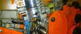
Secure the regulator in a vice with soft jaws to the boss of terminal 1 of housing 5.
It is forbidden to attach the regulator to the upper and lower parts of the housing 5, as this may lead to its deformation or destruction.
Unscrew the lock nut 7 and unscrew the adjusting screw 8, loosening the spring 6 of the balancing piston. Next, unscrew with a special 50 mm socket wrench mod. and 806.04.006 the top cover 15 and remove the spring b and the balancing piston 9 along with the inlet 11 and exhaust 4 valves, remove the sealing collar 20.
Important TOP 2 modifications of the ZIL-137 army truck with increased cross-country ability
Unscrew the bottom cover 1 with the noise muffler. To remove the noise silencer, you need to unscrew it from the bottom cover and remove filter 3 with a spring and unloading piston 12 assembly. To disassemble the unloading piston 12, you need to remove two thrust rings 18 and 19 with round nose pliers.
To disassemble check valve 10, use round pliers to unscrew washer 22 and remove check valve with spring 21.
After disassembling the regulator parts, wash them with clean gasoline or acetone, dry them and carefully inspect them.
The surface of body parts must not contain cracks, hairs or other defects visible to the eye. Parts must be cleaned of rust and burnt marks. All rubber parts must be replaced with new ones.
The procedure for assembling the regulator is the reverse of disassembling. The threads on the lower 1 and upper 15 covers must be lubricated with graphite grease during assembly.
Adjusting and checking the pressure regulator after assembly. Install the pressure regulator on the test bench (see Fig. 2) and connect the device according to the diagram shown in Fig. 1), a. Then apply and release air at a pressure of 1.4 MPa three times into terminal I. In this case, terminal V must be plugged.
If the limits of the adjustable air pressure in outlet II do not correspond to 0.65...0.8 MPa, use the adjusting bolt 8 to adjust the pressure to the required limits. In this case, you should strive to achieve the upper pressure limits, since due to shrinkage of the springs during operation, the set pressure may decrease.
After adjustment, check the regulator switch-on and switch-off pressure three times, and then lock the adjusting bolt.
By installing adjusting washers of different thicknesses under the spring of the unloading valve, it is necessary to adjust the response pressure of unloading valve 2. To do this, you need to block the air passage to terminals I and II using a plug. Increase the pressure in port I three times and when the pressure reaches 1.0...135 MPa, the safety valve should open and air should escape through port III of the regulator. After adjustment, clear passage to terminal II.
To check the regulator for leaks, it is necessary to set a pressure of 0.05 MPa in terminals I and II, while checking the tightness of the inlet valve
II, piston cuff 9 and unloading valve 2. The tightness of the check valve 10 is checked by setting a pressure of 0.45 MPa in port II. When washing, the appearance of air bubbles is not allowed for 1 minute.
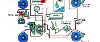
General structure of the brake system of trucks
Modern trucks of domestic and foreign production use a pneumatically driven braking system, which simultaneously acts as a source of compressed air for a number of other systems and mechanisms. The use of a pneumatic system is due to its high reliability, efficiency and versatility, and in the future it is unlikely to give way to systems operating on other principles.
The pneumatic system of all trucks is approximately the same; it includes a compressor, pipelines, a receiver (or receivers), several valves and actuators. The system also includes several devices that ensure its normal functioning in any conditions, as well as protection of its components from a number of negative factors. One of such devices is a moisture-oil separator, which compensates for some of the operating features of the compressor and ensures the removal of moisture and oil from the system, the presence of which can seriously harm the operation of valves and other units.
Operating rules
During use, the element requires virtually no maintenance. However, several rules will help extend the life of the system and individual elements of its design. Specialists and owners of KamAZ vehicles recommend taking into account the following points:
- The device must be installed correctly. It is important that the drain hose faces downwards. This will help quickly and smoothly remove condensate from the system. If you do not provide for this, quite quickly the body of the structure will begin to become covered with rust.
- Care should be taken to ensure the tightness of the system. Especially if a used separator was installed. To ensure high and reliable tightness, it is recommended to update the sealing elements. This will help protect the rubber diaphragms of the brake chambers from the harmful effects of fluid or oil.
Additionally, it is recommended to regularly inspect and maintain the device. The main reason why a moisture separator may fail is depressurization.
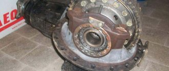
Purpose and place of the moisture-oil separator in the pneumatic system
The basis of the pneumatic braking system is a compressor, which provides air injection at a pressure sufficient for the operation of all mechanisms. However, the compressor has one feature: during its operation, oil is released into the air, used to lubricate the piston and other parts. It is impossible to prevent microscopic droplets of oil from entering the air, since without lubrication the compressor simply cannot operate.
Another problem is the air itself, which is taken from the atmosphere by the compressor. Atmospheric air always contains moisture, and the degree of humidity can be quite significant - when it enters the system, this moisture condenses, droplets are deposited on the surfaces of pipelines, valves and mechanisms, which leads to corrosion and other negative consequences.
Therefore, the pneumatic system must be equipped with a device that cleans the injected air from oil droplets and moisture. This problem is solved by a moisture-oil separator, which is installed immediately after the compressor. Passing through this unit, the air is dried and cleared of oil, and only after that it enters the receivers and then to the actuators.
It should be noted that after passing through the moisture-oil separator, the air still contains a small amount of oil and moisture, and therefore poses some threat to the system. Additional cleaning is carried out using receivers: when leaving the pipeline into the receiver, the air expands, its temperature drops, moisture condenses and settles on the walls of the tank, taking with it microscopic droplets of oil. Over time, oil and condensate accumulate at the bottom of the receiver, which is periodically removed using a specially designed valve.
The pneumatic systems of all trucks operate on this principle, and they use a limited number of types and models of moisture-oil separators that have a fundamentally identical design.
Pressure regulator KAMAZ
The pressure regulator is designed to automatically regulate pressure in the pneumatic system within the range of 0.65 0.8 MPa (6.5 8.0 KGS/SMZ), as well as to protect pneumatic drive units from contamination with oil and. excessive increase in pressure due to failure of the regulating device. The pressure regulator is connected by a pipeline directly to the compressor; attached with two bolts to the bracket.
Important Technical characteristics of modifications of the Chelyabinsk bulldozer B10
pressure regulator
The atmospheric outlet of the regulator is directed downward so that the condensate released by the regulator does not fall on other parts of the car.
Principle of operation
Compressed air from the compressor through terminal 1 of the regulator, filter 3, channel D and check valve 10 flows to terminal 111 and then into the air cylinders of the pneumatic drive. At the same time, through channel G, compressed air passes through cavity B under the balancing piston 9, which is acted upon by spring b. The outlet valve 4, connecting the cavity E above the unloading piston 12 with the environment through the outlet P, is open. The inlet valve 11, through which compressed air is supplied from the annular channel into the cavity E, is closed under the action of its spring in the same way as the unloading valve 2.
scheme
This state of the regulator corresponds to filling the air cylinders with compressed air from the compressor. When a certain pressure is reached in cavity B, the piston 9, overcoming the force of the spring 6, rises upward. Valve 4 closes under the action of the pusher, inlet valve 11 opens, and compressed air from the annular channel enters cavity E.
Under the influence of compressed Air, the unloading piston 12 moves down, the unloading valve 2 opens, and the compressed air from the compressor through outlet 4 exits into the environment along with the condensate accumulated in the cavity. In this case, the pressure in the annular channel drops and the check valve 10 closes. As a result, the compressor operates in unload mode without backpressure.
system pressure adjustment
When the pressure in port 3 and cavity B drops to a certain value, piston 9 moves downward under the action of spring b, Inlet valve 11 closes, and outlet valve 4 opens, communicating cavity B with the environment through pin 11. Unloading piston 12 rises upward under the action of a spring , valve 2 closes under the action of its spring, and the compressor again pumps compressed air into the cylinders.
Unloader valve 2 also functions as a safety valve. If the regulator does not operate at a pressure of 0.8 MPa (8.0 KGS/SMZ}, then at a pressure of 1.0 1.35 MPa (10 13.5 kgf/cm?) the valve will open, overcoming the resistance of its spring and the piston spring 12 The opening pressure of valve 2 is adjusted by changing the number of washers under the spring.
terminal for tire inflation
The pressure regulator has an air bleed valve, for example, for inflating tires, closed by cap 15. When screwing on the hose fitting for inflating tires, the valve is recessed, allowing access to compressed air into the hose and blocking the passage of compressed air to terminal 11. Before inflating tires, the pressure in the air cylinders should be lowered to the pressure corresponding to the activation of the regulator, since during the unloading mode of the compressor operation, air sampling is impossible.
Regulator malfunctions
The main malfunctions of the regulator are wear of rubber seals, cuffs, and rings.
regulator filter
Pressure Regulator Maintenance
It consists of periodically checking its operation and cleaning the filter (during seasonal maintenance). Replacement of rubber valve seals (repair kit). Pressure adjustment.
If the limits of the adjustable air pressure in the pneumatic system do not correspond to 0.65 0.8 MPa (6.5 8.0 kgf/cm), (: using the adjusting bolt, you should adjust the pressure to the required limits. In order to remove the filter, you must unscrew bottom cover 1. After this, you need to rinse the filter in gasoline and clean the internal cavities of the regulator and cover.
WATCH THE VIDEO
Types and design of moisture-oil separators
All devices used today for separating moisture and oil from compressed air have the same principle of operation, therefore they are designed according to the same principles, and differ only in the presence or absence of additional parts.
Currently, two main types of moisture-oil separators are used:
• With built-in air pressure regulator (RDV); • Without pressure regulator.
Moisture-oil separators with and without RDV have different mechanisms for removing condensate and oil. In addition, devices with built-in air pressure control make a separate regulator unnecessary, and therefore provide higher reliability of the entire pneumatic system.
Also, moisture-oil separators can be divided into two groups according to their design and operating principle:
• With radiator; • Without radiator.
In dehumidifiers with a radiator, two processes are used to dry the air - thermodynamic and dynamic; in devices without a radiator, only the dynamic process is used. These processes and their differences will be discussed below. The radiator is usually a thin-walled tube with fins, coiled into four to six oval turns.
Finally, all moisture-oil separators can be divided into two large groups:
• Electrically heated devices; • Devices heated with warm air from a compressor.
The first type of moisture-oil separators has a built-in heating element, which ensures defrosting of valves and other parts during winter operation. In devices of the second type, frozen valves are heated with hot air, and additional anti-freeze valves are provided to ensure satisfactory operation until defrosting.
Regardless of the type, all moisture-oil separators have a fundamentally identical design. The basis of the unit is a hollow body, in the upper part of which a guide vane is installed, and in the lower part there is a condensate discharge valve. The device may also contain various additional valves - a check valve, which prevents the flow of compressed air from the system back to the compressor when it is turned off, a safety valve, which ensures the operation of the water-oil separator when the condensate freezes in the radiator, and others.
The guide vane can have two types of design:
• Hollow screw with a row of disks (impeller) - only in moisture-oil separators without RDV; • Spiral channel on the RDV body.
Also, in moisture-oil separators with and without RDV, condensate discharge valves of different designs are used:
• In devices with RDV - a spring valve that opens simultaneously with the opening of the pressure regulator valve; • In devices without RDV - a spool-type diaphragm valve, opened due to air rarefaction that occurs when the pressure regulator is activated.
Let's consider the operation of moisture-oil separators with and without a built-in pressure regulator.
Features of the device
The dryer is installed after the compressor. Tubular and adsorption devices are used in trucks. Devices of the second type are more efficient. Dryers consist of:
- Heater;
- Pressure regulator;
- Silencer;
- Patrona.
The main elements are located in the cast valve body of the MAZ 5440 air dryer.
The main components of the device provide control of the pneumatic system. The housing contains safety and check valves. On the surface there are fittings and pipes.
The MAZ dehumidifier has a heater. At temperatures below +5 degrees, the device maintains the microclimate necessary for the adsorbent. The heater prevents the water in the system from freezing.
Protects against tears and deformations. There is a connector on the housing to connect the heating element. A muffler is installed at the bottom to eliminate unpleasant noise.
A drying cartridge is fixed in the upper part. The spare part is used to remove moisture from incoming air. The cartridge contains a cylindrical container with an adsorbent. The part is installed on the filters. It is pressed from above by a spring. There is a threaded hole at the bottom of the cartridge.
Operating principle of a moisture-oil separator without RDV
Let's consider the principle of operation of a moisture-oil separator without a regulator, but with a radiator.
The air coming from the compressor is quite hot, so the easiest way to remove moisture from it is to lower its temperature, causing the moisture to condense into droplets. The radiator serves precisely for this purpose - the air in it is cooled and gives off a significant part of the moisture. This is where the thermodynamic process of moisture separation is used.
Next, the air enters directly into the moisture-oil separator, where it hits the disks of the guide apparatus - here the drops of oil and condensate are separated, which flow to the bottom of the housing. The purified air enters the vehicle's pneumatic system through a hollow screw.
Over time, water and oil accumulate in the radiator and at the bottom of the unit housing, and it must be removed - this is ensured by a membrane-type condensate discharge valve. It works simply: when the RDV is triggered, the pressure in the moisture-oil separator drops and becomes below atmospheric pressure, as a result of which the membrane, under the influence of the pressure difference, rises and opens the valve, and the condensate is removed by gravity. At the same moment, the radiator is purged.
Water-oil separators of this type are usually equipped with a safety valve, which is necessary to ensure the device operates when condensate in the radiator freezes. The valve opens when the radiator is obstructed (as a result of which the air pressure at the inlet increases), and allows air directly to the impeller, bypassing the radiator. Defrosting of condensate occurs under the influence of warm air leaving the compressor; usually, it takes 5 to 10 minutes of compressor operation to restore the radiator.
Problems at work
They can occur in winter. At sub-zero temperatures, during long periods of inactivity, the relief valve may simply freeze. The pressure regulator then works as a safety element, providing pressure relief when a critical level is reached. However, when the compressor starts, hot air enters the dehumidifier. KamAZ, idling for about 5-10 minutes, will be suitable for operation, since this air, at its temperature, completely warms the valve and restores its operation.
Operating principle of a moisture-oil separator with RDV
In essence, the operation of a moisture-oil separator with a pressure regulator is no different from that described above; the differences lie only in the condensate discharge mechanism.
The air from the compressor enters the radiator, where it is cooled and dried. Next, the air enters the spiral channel formed between the housing of the RDV and the housings of the moisture-oil separator, here it is cleared of oil and enters the pneumatic system through a check valve. Condensate accumulates at the bottom of the moisture-oil separator housing; it is removed when the pressure regulator valve opens, which simultaneously opens the condensate discharge valve. Also, when the RDV is triggered, the radiator is purged and completely cleansed of condensate.
Types of moisture-oil separators used in domestic trucks
Today, all trucks and buses of domestic production (KAMAZ, ZIL, Ural, PAZ, NefAZ, LiAZ and others), as well as trucks and buses MAZ, KrAZ, LuAZ and others are equipped with the same models of moisture-oil separators produced by PAAZ, RAAZ and some other enterprises.
The most widely used today are moisture-oil separators of models 14.3512010-10 and the improved 16.3512010, 100-3511110-10 and its analogue 25-3511110-11 (with a 24 V electric heater), and others.
When choosing an oil-water separator for a car, it is necessary to take into account the model of the previously installed device, as well as the possibility of using analogues. At the same time, it is recommended not to replace a moisture-oil separator without an RDV with a device with a built-in regulator, and vice versa, since this will require making a number of changes to the pneumatic system (remove or add a pressure regulator).
Features of operation and maintenance of the moisture-oil separator
The oil/water separator requires minimal attention and maintenance and will cause minimal problems to the truck driver over its entire service life. However, it is necessary to mention some features, knowledge of which will help to avoid breakdowns and ensure high-quality operation of the pneumatic system.
There are several recommendations that should be followed when installing a new oil-water separator on a car. Firstly, the device must be installed so that the drain fitting is directed downward - in this case, when discharging condensate, the water will drain to the ground. Otherwise (if the fitting is directed to the side), condensate can cause corrosion and breakdown of nearby components and assemblies. And, secondly, when installing a moisture-oil separator, it is necessary to use rubber sealing elements that will ensure the tightness of the system.
In the winter season, there is a high risk of freezing of the condensate discharge valve, especially when the pneumatic system is operating in the compressor unloading mode. You can avoid this trouble by simply stopping the engine.
In general, the moisture-oil separator is highly reliable and efficient; its presence ensures the high-quality functioning of the pneumatic braking system, which guarantees reliable operation of the car or bus.
Heating
Another classification of dehumidifiers is the heating method. The following types of devices are distinguished:
- Electrical. In this case, the design provides a heating element that promotes the movement of the valves during vehicle operation in winter.
- Mechanical. Heating is carried out using the energy of hot air. Additionally, the designers provide anti-freeze valves that ensure operation of the device even at the lowest temperatures.