Hydrostatic steering control - MTZ-1221 (2009):
1221-3400010-B 1 2 3 4 5 6 6 6 6 6 7 8 8 9 10 11 11 12 13 14 15 16 17 18 18 19 19 19 20 21 22 23 24 24 25 26 27 28 28 29 29 30 31 32 33 34 35 36 37 38 38 38 39 40 40 40 41 41 42 43 44 45 46 47 48 49 50 51 52 53 53 54 55 56 57 58 59 60 61 62 63
List of components from Hydrostatic steering control for MTZ-1221 (2009)
Parts diagrams are for reference purposes only! We do not sell all spare parts for the hydrostatic steering control for the MTZ-1221 (2009) presented in this list. If there is a link “Show prices” in the right column, these spare parts from “Hydrostatic steering control” are on sale. Availability in warehouses for details and prices, see the product card. If there is no “Show cost” link in the right column, we do not sell such parts and do not accept orders for them.
| № | Part code | Name | Part Information | Show all prices |
Application of a metering pump in hydraulic steering systems
_______________________________________________________________________________________
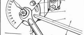
Any wheeled vehicle requires a high-quality and efficient steering system. Modern steering mechanisms are very similar to each other. The basic structural hydraulic diagram of a mobile machine contains three main circuits - a hydrostatic transmission, a hydraulic drive of working parts, and a brake and steering hydraulic system. As a rule, the steering and brake systems are supplied by one hydraulic pump. Depending on the operator's command and the influence of external resistance forces on the machine, the priority valve automatically divides and directs the flow of working fluid into the corresponding mentioned hydraulic circuits. Rice. 1. Steering diagram of construction equipment A typical steering system (Fig. 1) contains a gerotor (planetary) metering pump (hydraulic steering wheel), which is mechanically connected to the steering wheel, a block of valves (anti-shock and anti-cavitation), as well as actuating hydraulic cylinders. The flow of working fluid from the feed pump enters the steering system through the priority valve.
Rice. 2. Typical designs of steering components In Fig. Figure 2 shows illustrations of typical designs of the main hydraulic steering components - priority valve (a), valve block (b) and metering pump (c). Schematic diagram in Fig. Figure 3 shows a typical non-reactive steering system with open class=”aligncenter” width=”368″ height=”283″[/img] Fig. 3. Typical non-reactive steering system with an open center Here, the reaction force (from the ground) when turning the wheels is not transmitted to the steering wheel of the car. The flow from the constant displacement pump passes freely through the hydraulic steering wheel and returns to the hydraulic tank when the steering wheel is in the neutral position. Turning the steering wheel opens the rotating spool inside the metering pump, and hydraulic fluid from the feed pump with a constant displacement enters the cavities of the actuating hydraulic cylinders. The wheels of the car are turning. From the opposite cavities of the hydraulic cylinders, the working fluid, passing through the hydraulic steering wheel, is directed to be drained into the hydraulic tank. When the steering wheel is turned, the metering pump ensures that a certain (fixed portion) flow of working fluid enters the hydraulic cylinders of the steering system. The magnitude of this flow rate depends on the rotation angle of the internal spool-bushing pair (i.e., the steering wheel) and the working volume of the hydraulic steering wheel. Actuating hydraulic cylinders also turn the wheels of the machine strictly at a certain angle, proportional to the value of the fixed flow rate. The angle of rotation of the wheels of the car is strictly proportional to the angle of rotation of the steering wheel. If, while driving, the wheels of the machine are exposed to external forces, the overload protection system comes into operation. As can be seen from the diagram, the steering mechanism (metering pump) is in the neutral position and the working channels leading to the actuating hydraulic cylinders are closed. When external force is applied to the wheels, pressure increases in the working circuit of the actuating hydraulic cylinders. As soon as this pressure exceeds the settings of the anti-shock valves, they will open and allow part of the working fluid to pass from the loaded cavities of the steering hydraulic cylinders into the drain hydraulic line. The pistons of the hydraulic cylinders will move a small amount, and a vacuum of the working fluid will occur in the opposite cavities, which leads to the negative phenomena of cavitation. However, at this moment, anti-cavitation (make-up) valves automatically open and compensate for the lack of working fluid, directing it from the drain line into the corresponding cavities of the steering hydraulic cylinders. To improve the overall steering performance, a hydraulic system is introduced that is insensitive to external loads. This is an LS (Loadsensing) system. Compared to conventional (traditional) LS hydraulic circuits, the system constantly compares changes in flow and pressure during machine operation and ensures minimal energy losses. The LS system and planetary metering pump are used in conjunction with a priority flow regulator. Rice. 4. Priority valve diagram In Fig. Figure 4 shows a schematic diagram of a priority valve. It functions as a divider and flow regulator from the feed pump to the steering and brake circuits of the hydraulic system. Here p is the inlet channel of the priority valve, to which the working flow from the feed pump is supplied; the RS channel supplies the steering system of the vehicle with working fluid, the TC channel is the line of the secondary circuit of the brake system; pp – control line (pilot pressure). The stiffness of the spring pressing the spool of the priority valve corresponds to the control pressure pp = 0.4; 0.7 or 1.0 MPa. Let's consider the operation of the priority valve in the hydraulic system.
Rice. 5. Diagram of the steering circuit in the initial position In Fig. Figure 5 shows a diagram of the steering circuit in the initial position. The feed pump does not work, the operating pressure p and control pressure pp are equal to zero, the LS line is connected to the drain, the working channels A and B of the steering hydraulic cylinders are locked. In this case, the priority valve spool is in the upper position under the action of the spring and, with its channels, connects the line from the supply pump to the hydraulic steering wheel of the hydraulic system. The brake circuit is disconnected from the feed pump. When the car moves in a straight line, the steering wheel and, accordingly, the metering pump are in the neutral position. Discharge line p is blocked, channel LS is connected to drain. When the pump is running, the spool, under the influence of control pressure pp, moves down, overcoming the resistance of the spring. The flow of working fluid is directed into the vehicle line to the brake circuit. However, the discharge line p is connected to the feed pump through the throttle in the spool of the priority valve, i.e. in the PC line the working fluid is under pressure. This is necessary to generate the control signal pp and bring the steering system into operation with a minimum time delay. When the steering wheel is turned, the metering pump opens the path of working fluid from the supply pump to the corresponding cavities A of the hydraulic cylinders. Their opposite cavities B are connected to the drain. The pressure p in the PC line drops, the level of the control signal pp becomes lower, and the spool of the priority valve begins to rise under the action of the spring. At the same time, part of the working flow enters the LS channel and is supplied through the control throttle to the spring-loaded end cavity of the priority valve spool. These processes cause stable movement of the spool under conditions of modulation (high-frequency pressure fluctuations), balanced by control pressure pp from the PC line on one side and on the opposite side - pressure in the cavities of the steering cylinders and spring force. As a result, the pressure drop across the hydraulic steering wheel is equal to the priority spool spring setting value. Therefore Δр = рр – LS = р1 – р2. At this stage, the priority valve becomes a pressure regulator for the metering pump, forming flow control through Pressure CONTROL. This guarantees a constant flow rate entering the hydraulic cylinders for turning the wheels, regardless of changes in the external forces acting on them. Turning the steering wheel immediately changes the connections of the channels inside the rotating spool pair of the metering pump. Increasing the angle of rotation increases the working volume of the hydraulic steering wheel and ensures that the required volume of working fluid enters the actuating hydraulic cylinders in order to turn the wheels by a given amount. Typically, the range of rotation angle of the hydraulic steering spool is from 0 to 15°.
Rice. 6. Scheme of connecting channels when turning the steering wheel. Scheme in Fig. 6 illustrates this action. When the steering wheel is turned, the pressure p1 and p2 increases as a result of an increase in the load in the working cavities of the actuating hydraulic cylinders. However, the pressure difference due to the LS channel with the control throttle does not depend on its magnitude. The priority valve spool is in the operating position, strictly dosing the necessary flow required by the steering system. The remaining working fluid is sent to the brake system circuit. If the pressure p2 in the working cavities of the hydraulic cylinders increases, and in the LS channel it reaches 15.0 MPa, the safety valve in this circuit will open. But as the pressure p2 increases, the pressure p1 and, accordingly, the control pressure pp also increases. It begins to compress the spring more strongly and lowers the priority valve spool down. This action causes the flow of working fluid into the brake circuit to increase. In practice this means the following. If the machine experiences a lot of resistance when turning the wheels or they have reached their extreme angular position, then when the operator presses the pedal, the braking system will operate effectively. Here we examined the most fundamental issues of the operation of steering systems of hydraulic wheeled vehicles, which include motor graders, front loaders, logging, agricultural and other special equipment. The development of hydraulic technology has made it possible to create advanced control systems that are produced by well-known companies. The design features of such systems are described in the manufacturers' literature.
_______________________________________________________________________________________
_______________________________________________________________________________________
- 970 Elite
- TLB 860
- Cat 422
- Cat 428
- Cat 434
- Cat 444
- 3 CX Super
- 4 CX
- 5 CX
- WZ30-25
- XT860/XT870
_______________________________________________________________________________________
- WB 97S
- WB 93R
- Hyundai H940S
- B110
- B115
- Hidromek HMK 102B
- Hidromek HMK 62SS
_______________________________________________________________________________________
- Mobile cranes
- Cranes manipulators
- Motor graders DZ-122,143
- Excavator EK-14
- Kamaz truck repair
- MAZ truck repair
- TL 65
- TL 120
- TL 310
- Cat 914
- Cat 924
- Caterpillar 950
- Caterpillar 966
_______________________________________________________________________________________
- LW500F
- ZL30G
- ZL50G
- LW321F
- XGMA XG932
- XGMA XG955
- Design of Terex, Komatsu, Cat loaders
- ZW250
- ZW310
- ZW220
- ZW180
- W130
- W170
- W190
- W270
- L34
- Adjusting the D-180 engine
- Transmission T-170
- Assembly of gearboxes T-170, T-130
- Adjusting the T-170 clutch
- Hydraulic and mounted systems T-170
- Main gear T-170, T-130
- Diesel injection pump D-160
- Servo mechanism of clutch T-130, T-170
- Onboard clutches T-130
- Final drive of the T-130 tractor
- Rotation control mechanism T-130
- Hydromechanical transmission TO-18/TO-18B
- Hydraulic system GMP TO-18/TO-18B Amkodor
- Hydraulic system TO-18
- Hydraulic system components TO-18/TO-18B Amkodor
_______________________________________________________________________________________
- Design of rack and pinion hydraulic cylinders
- Types of positive displacement hydraulic pumps
- Rotary screw pumps - Design and operating principle
- Characteristics and design of gear pumps
- Pump control diagram in a closed hydraulic system
- Hydraulic distributor device with proportional control
- Hydraulic systems of special equipment - operation and maintenance
- Application of hydrostatic transmissions for special equipment
- Application of cartridge electrically controlled valves
- Design and diagrams of cartridge plug-in hydraulic valves
- Characteristics of Screw-in Hydraulic Cartridge Valves
- Sequence valve and pressure reducing valve operating diagrams
- Variable displacement hydraulic pump regulator
- Load Sending System for Variable Pumps
- Hydraulic distributors - Control systems
- Control diagrams for working hydraulic units of special equipment
Not available:
| № | Part code | Name | Part Information |
| 1221-3400010-B | Hydrostatic steering control | Quantity 1 Model 1221 Group Steering control Subgroup Steering control assembly Serial part number 010 Additionally Interchangeable with a part previously released under the same number | Not available |
| 85-3407107 | Plank | Quantity 1 Model 85 Group Steering control Subgroup Power steering pump Part number 107 | Not available |
| 1221-3407030 | Oil line | Quantity 1 Model 1221 Group Steering control Subgroup Power steering pump Part serial number 030 | Not available |
| 1221B-3407050 | Oil line | Quantity 1 Model 1221B Group Steering control Subgroup Power steering pump Part serial number 050 | Not available |
| 1221B-3407040 | Oil line | Quantity 1 Model 1221B Group Steering control Subgroup Power steering pump Part serial number 040 | Not available |
| 80B-3407012 | bracket | Quantity 1 Model 80B Group Steering control Subgroup Power steering pump Part number 012 | Not available |
| ShP8 | Washer | Quantity 7 | Not available |
| M8 | screw | Quantity 1 | Not available |
| XC-31 | Clamp or clamp “Norma” 25-40 | Quantity 2 | Not available |
| 1221-3407013 | bracket | Quantity 1 Model 1221 Group Steering control Subgroup Power steering pump Part serial number 013 | Not available |
| M8x20 | Bolt | Quantity 1 | Not available |
| 70-3506027 | Sleeve | Quantity 5 Model 70 Group Brakes Subgroup Air brake piping Part serial number 027 | Not available |
| 70-3407163 | Bracket | Quantity 1 Model 70 Group Steering control Subgroup Power steering pump Part number 163 | Not available |
| 1221-3407200 | Oil tank | Quantity 1 Model 1221 Group Steering control Subgroup Power steering pump Part number 200 | Not available |
| XC-26 | Clamp | Quantity 2 | Not available |
| 952-3407014-10 | Hose | Quantity 1 Model 952 Group Steering control Subgroup Power steering pump Serial number of part 014 Additionally Not interchangeable with a part previously released under the same number | Not available |
| 85-3407105-04 | Bolt | Quantity 1 Model 85 Group Steering control Subgroup Power steering pump Part number 105 | Not available |
| 923-3407080 | Oil line | Quantity 1 Model 923 Group Steering control Subgroup Power steering pump Part number 080 | Not available |
| PM1/2 | Washer | Quantity 5 | Not available |
| Ф80-3407157 | Washer | Quantity 5 Model F80 Group Steering control Subgroup Power steering pump Part number 157 | Not available |
| LAGC160-10/200-140M01-100 | Metering pump | Quantity 1 | Not available |
| OSPC1600N150G0030 | Metering pump | Quantity 1 | Not available |
| SUB160-140-200-1 | Metering pump | Quantity 1 | Not available |
| Ф80-3407134 | Union | Quantity 3 Model F80 Group Steering control Subgroup Power steering pump Part serial number 134 | Not available |
| 2522D-3407085-01 | Oil line | Quantity 1 Model 2522D Group Steering control Subgroup Power steering pump Part serial number 085 | Not available |
| 680-4607140-11 | High pressure hose | Quantity 3 Model 680 Subgroup 4607 Part serial number 140 Additionally Not interchangeable with a part previously released under the same number | Not available |
| 1221-3407140 | Valve | Quantity 1 Model 1221 Group Steering control Subgroup Power steering pump Part number 140 | Not available |
| 40-4607033-A-01 | Washer | Quantity 2 Model 40 Subgroup 4607 Part serial number 033 Additionally Interchangeable with a part previously released under the same number | Not available |
| PM24 | Washer | Quantity 2 | Not available |
| H-036-12-010 | Stub | Quantity 2 | Not available |
| 1321-3407018-01 | Hose | Quantity 1 Model 1321 Group Steering control Subgroup Power steering pump Part number 018 | Not available |
| 1221-3407020 | Oil line | Quantity 1 Model 1221 Group Steering control Subgroup Power steering pump Part number 020 | Not available |
| 70-3407146 | Plank | Quantity 3 Model 70 Group Steering control Subgroup Power steering pump Part number 146 | Not available |
| M8x30 | Bolt | Quantity 3 | Not available |
| M10x25 | Bolt | Quantity 2 | Not available |
| ShP10 | Washer | Quantity 1 | Not available |
| 102-3407014 | Bracket | Quantity 1 Model 102 Group Steering control Subgroup Power steering pump Part serial number 014 | Not available |
| 70-4607158 | Pad | Quantity 2 Model 70 Subgroup 4607 Part number 158 | Not available |
| M8x40 | Bolt | Quantity 2 | Not available |
| 017-022-30-1-4 | Ring | Quantity 2 | Not available |
| M8x35 | Bolt | Quantity 2 | Not available |
| Ts50-3405215 | Hydraulic cylinder | Quantity 2 Model Ts50 Group Steering control Subgroup Power steering cylinder Serial part number 215 | Not available |
| PM3/8 | Washer | Quantity 8 | Not available |
| Ф80-3407114 | Washer | Quantity 8 Model F80 Group Steering control Subgroup Power steering pump Serial part number 114 | Not available |
| 952-3407020 | Adapter | Quantity 2 Model 952 Group Steering control Subgroup Power steering pump Part serial number 020 | Not available |
| Ф80-3407201 | Bolt | Quantity 4 Model F80 Group Steering control Subgroup Power steering pump Part number 201 | Not available |
| 952-3407100-12 | High pressure hose | Quantity 2 Model 952 Group Steering control Subgroup Power steering pump Serial number of the part 100 Additionally Not interchangeable with a part previously released under the same number | Not available |
| 1221-3407010-B | Tee | Quantity 1 Model 1221 Group Steering control Subgroup Power steering pump Serial part number 010 Additionally Interchangeable with a part previously released under the same number | Not available |
| 1-1-Ц6-хр | Oil can | Quantity 4 | Not available |
| M20x1.5 | screw | Quantity 4 | Not available |
| Ф80-3405103 | Lock washer | Quantity 4 Model F80 Group Steering control Subgroup Power steering cylinder Serial part number 103 | Not available |
| C20 | Washer | Quantity 4 | Not available |
| Ф80-3405102-В | Sleeve | Quantity 4 Model F80 Group Steering control Subgroup Power steering cylinder Serial number of the part 102 Additionally Interchangeable with the part released earlier under the same number | Not available |
| Ф80-3405107 | Spherical bushing | Quantity 8 Model F80 Group Steering control Subgroup Power steering cylinder Serial part number 107 | Not available |
| Ф80-3405109 | Sealant | Quantity 8 Model F80 Group Steering control Subgroup Power steering cylinder Serial part number 109 | Not available |
| Ф80-3405108 | Sealing cup | Quantity 8 Model F80 Group Steering control Subgroup Power steering cylinder Serial part number 108 | Not available |
| 4×36 | Cotter pin | Quantity 4 | Not available |
| 70-4605316 | Thrust nut | Quantity 4 Model 70 Subgroup 4605 Part number 316 | Not available |
| 102-3405103 | Finger | Quantity 4 Model 102 Group Steering control Subgroup Power steering cylinder Part serial number 103 | Not available |
| 1222-2301021-B | bracket | Quantity 1 Note right Model 1222 Group Front drive axle Subgroup Front drive axle housing and gearbox Serial part number 021 Additionally Interchangeable with a part previously released under the same number | Not available |
| 1222-2301022-B | bracket | Quantity 1 Note left Model 1222 Group Front drive axle Subgroup Front drive axle housing and gearbox Part serial number 022 Additionally Interchangeable with a part previously released under the same number | Not available |
| 1221-3407010-B-01 | Tee | Quantity 1 Model 1221 Group Steering control Subgroup Power steering pump Serial part number 010 Additionally Interchangeable with a part previously released under the same number | Not available |
| 1520-2308079 | Hairpin | Quantity 4 Model 1520 Group Front drive axle Subgroup 2308 Part number 079 | Not available |
| 1520-2308077 | Sleeve | Quantity 4 Model 1520 Group Front drive axle Subgroup 2308 Part number 077 | Not available |
| ShP16 | Washer | Quantity 4 | Not available |
| M16 | screw | Quantity 4 | Not available |
| 1221-3407101 | bracket | Quantity 1 Model 1221 Group Steering control Subgroup Power steering pump Part serial number 101 | Not available |
| 70-4607158-01 | Pad | Quantity 1 Model 70 Subgroup 4607 Part number 158 | Not available |
| Ф80-3405112 | Union | Quantity 2 Model F80 Group Steering control Subgroup Power steering cylinder Serial part number 112 | Not available |
Design solution of the metering pump
Despite the variety of design solutions for metering pumps, they are all of the same type and consist of:
- hydraulic motor;
- valve block;
- spool valve mechanism;
- rings for rotating the internal gear in each of the steering positions;
- outer gear protective casing;
- drive shaft.
Often a gear-type unit is used as a hydraulic motor. Inside, between the suction and discharge lines, working chambers are formed that form gear teeth. When the angle of repetition of the steering wheel changes, the gears move, the volume of the chamber changes and, as a consequence, the amount of displaced working fluid.
The metering pump is characterized by compact dimensions and low weight, which allows it to be easily integrated into any hydraulic systems. It is installed on the steering column bracket and is connected to other components of the hydraulic system through a hose system. It works automatically, instantly responding to changes in the steering wheel position.
Issues of selection, replacement and maintenance of a metering pump
During the operation of the HPS, high pressures operate in the metering pump, and the parts of this unit are also subject to intense mechanical loads - all this leads to wear of components, increased gaps and breakdown of the unit as a whole. A malfunction of the LP is indicated by the lack of reaction from the steering wheel when turning it and, on the contrary, spontaneous rotation of the steering wheel, as well as incorrect operation of the steering. If these malfunctions occur, you should diagnose the steering parts and the metering pump. This work must be performed in accordance with the repair and maintenance instructions for the tractor/self-propelled machine, or in accordance with the instructions for a separate unit.
If a malfunction of the metering pump is detected, repairs should be carried out using repair kits. The most common problem with ND is wear and damage to sealing elements - rubber rings, seals and gaskets. Damage also occurs in bearings, shafts, hydraulic motor plates, etc. All these parts and seals are now offered as repair kits, which reduces the cost of repair work.
If the pump cannot be repaired, you must buy a new unit. A replacement metering pump should be of the same type and model as was previously installed. If necessary, you can use an analogue, but it must have the same performance (or at least no less performance) and a suitable drive design. Additionally, a set of fasteners and related parts may be required to perform installation work. Installation and commissioning of a new metering pump is carried out in accordance with the instructions. With the correct selection and replacement of the LP, the tractor steering will work reliably and efficiently under any operating conditions.