Features of operation and repair of the autonomous system on KamAZ trucks
The parking heater (in common parlance, autonomous heater) on KamAZ is used to heat the cab when the main engine is not running. Depending on the design, devices are divided into “dry” and “wet”. The first ones use a flame torch to heat the air that is supplied to the cabin, and the second ones heat the coolant of the car’s engine cooling system. In this case, the cabin is heated by a standard stove.
Principle of operation
Heaters from this manufacturer operate on the principle of supplying outside air to the heating compartment. When fuel is burned, energy is released that heats the air. Only after this is hot air supplied to the vehicle interior.
To select the optimal power, a special regulator is used with the ability to be fixed in a given position. After the user selects the optimal operating mode, the heater will independently maintain the set temperature.
The basic operating principle of the Planar autonomous vehicle:
How does it work
The heater is an autonomous heat source and operates independently of the car engine. The device includes:
- burner;
- fuel pump;
- water pump;
- Control block;
- remote control panel;
- connecting wires.
The operating principle of the 14TS-10 heater is based on the transfer of heat from burnt fuel to a coolant pumped through a heat exchanger. The device is located under the hood and connected to the engine cooling system.
Before putting the autonomous heater into operation, an automatic check of the functionality of all its components is carried out. Having received information about the working condition, the control unit gives a command to ignite the device. At the same time, the circulation pump is turned on. There are 2 heater operating programs: “Economical” and “Pre-start”. The first one has lower power consumption, and the execution time is 8 hours. The second is more energy-intensive, but completed in 3 hours. You can stop the device manually at any stage of the cycle.
The fuel mixture is ignited after the combustion chamber is purged with air. A glow plug is used as a fire source, which remains in operation until the torch burns steadily. Diesel fuel is supplied to the combustion chamber by an electromagnetic fuel pump from its container or car tank. After heat is transferred to the walls of the heat exchanger, the exhaust gases are released under the car.
Automation ensures safe operation of the device and turns it off in the following cases:
- 2 unsuccessful startup attempts;
- flame torch failure;
- increase in network voltage more than 30 V and decrease below 20 V;
- heat exchanger overheating.
The first start-up and periodic switching on of the heater during the “Pre-start” program are carried out in the “Full” mode, and in the “Economic” mode - in the “Medium” mode. In this case, fuel consumption is 2 and 1.2 l/hour.
Remote Control
The control panel (hereinafter referred to as the remote control) is intended for use as part of the heater as a device that provides manual control of the heater.
The control panel is designed for:
- starting and stopping the heater in manual mode;
- operating mode selection;
- cabin heater fan control;
- displaying the status of the heater (working, not working, or not working due to a malfunction).
Control panel structure and operation with it
On the front panel of the remote control there are: two key switches (pos. 1 and 2), an LED (pos. 3), a knob (potentiometer) (pos. 4) see fig. 3.
Rice. 3 – Front panel of the remote control
Switches are designed to execute the following commands:
- the switch (position 1) is used to start (position “I”) and stop the heater (position “O”);
- switch (position 2) is used to select the operating mode:
a) pre-start mode is intended to warm up and maintain a warm engine for 3 hours; b) economy mode is designed to keep the engine and driver's cabin warm when the engine is not running; The maximum operating time in this mode is 8 hours. The switch positions are indicated by the numbers “3” and “8”, respectively.
The potentiometer knob (item 4) is used to control the cabin heater fan (provided that the coolant temperature is more than 55 C°, and the cabin heater switch on the panel in the cabin is in the “OFF” position, and the vehicle weight is on) as follows: a ) when the potentiometer knob is set to the extreme left position, the cabin heater fan will be turned off; b) when the potentiometer knob is set to the extreme right position, the cabin heater fan will operate continuously; c) when setting the potentiometer knob between the extreme positions, the fan will turn on cyclically. Cycle duration is 10 minutes. For example, if the knob is set to a position in which the heater fan runs for 4 minutes, then only after 6 minutes it will turn on again for 4 minutes, etc. Thus, it will work until the position of the potentiometer knob is changed or until the heater is turned off. After each change in the position of the potentiometer knob (between the extreme positions), the next switching on of the cabin heater fan will occur in the interval from 2 to 8 minutes.
The LED (position 3) shows the status of the heater:
- lights up - when the heater is operating;
- flashes - in case of a malfunction (accident). The number of flashes after a pause corresponds to the fault code (see table 2).
- does not light up - when the heater is not working.
Malfunctions and their elimination
The organization of searching for defects is described in the operating instructions for the device. Malfunctions that arise during operation and require complete or partial disassembly of the heater must be carried out by specialists from repair organizations. All faults, except the inability to turn on the heater, are indicated by a blinking LED on the control panel.
Error codes
The heater is equipped with a monitoring system for the proper operation of components and individual elements. If a defect occurs, the automation classifies it and notifies the driver by the number of LED flashes. The list of possible malfunctions is summarized in a table indicating the necessary actions to be taken to restore the device to operability. Error codes correspond to the number of blinks of the indicator.
Malfunctions are collected into 10 groups based on the same causes of occurrence and methods for eliminating defects. The table is given in the heater operating manual.
Why doesn't it start
If, when you try to turn on the heater, the LED indicator does not light up and the start-up does not occur, then there may be several reasons for this situation, but they are all related to a lack of power:
- 25 A fuse blown;
- faulty electrical wiring;
- The contacts in the connectors have oxidized.
If there is power to the control panel, the cause of the malfunction may be a defect in any of the controlled elements. In this case, the defect code will be shown by a flashing indicator.
How to turn it on
Starting and changing operating modes of the “autonomy” are carried out from the control panel. To start the heater, you need to select a program using the mode key (3 or 8 hours) and turn on the power switch. The LED will light up and the control unit will begin executing the program. After testing is completed and the blower, pump and fuel pump are turned on, the burner will ignite. The program runs automatically and does not require driver intervention. At the end of the set time, the device will stop.
Restart is possible after a power failure; its subsequent activation - no earlier than after 10 seconds.
Repair
Despite the fact that the manufacturer recommends repairing breakdowns associated with disassembling an autonomous heater in specialized workshops, many drivers and car owners prefer to fix the faults themselves. The fairly high price of the work pushes them to this decision.
Most often, the flame sensor fails and the fuel line becomes clogged. The work is simple and does not require the use of special tools.
Regular scheduled maintenance will help reduce the number of defects.
For this type of heaters, there are 2 types of maintenance: daily and seasonal. The volumes, timing and list of work performed are given in the technical documentation for the device.
How to install
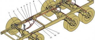
The 14TS-10 heater is installed on the frame cross member under the hood in front of the radiator. The device is mounted standard: bolted. The boiler's pipes cut into the standard cooling system. Fuel supply is possible from its own tank installed outside the engine compartment, or from the fuel system. Exhaust gases are removed through a corrugated metal hose under the bottom of the car between the cab and the body (trailer).
This placement of the autonomous unit allows for maximum removal of exhaust gases from the cabin, minimizing the length of the cooling system pipes and obtaining an additional heat source in the engine compartment.
preheater, error codes, how to start, won’t start, malfunctions, repairs
PZD KamAZ is a liquid-type diesel heater.
What is PZD
A pre-heater on KamAZ is necessary to warm up a cold engine equipped with a liquid cooling system. It also prevents glass from icing up.
Device
The device includes the following elements:
- heat exchanger;
- burner;
- air blower;
- glow plug;
- flame sensor;
- thermal safety mechanism;
- temperature indicator;
- inlet and outlet pipe;
- flame swirler and solenoid fuel valve;
- exhaust pipe;
- high pressure fuel pump and harness;
- stabilizer and fan;
- pump unit and fuel tank valve.
Technical characteristics of the engine pre-start fuse:
| Heating capacity, kW | 12+1 |
| Fuel fluid consumption, l | During operation - 1.6 At idle - 0.7 |
| Diesel fuel requirements | GOST 305-82 (50% diesel + 50% gasoline) |
| Voltage, V | Up to 30 |
| Electrical power consumption, W | 70+10 |
| Rated voltage, V | 24 |
| Minimum amount of liquid for heating, l | 10 |
| CO content of gases at the outlet | No more than 4 |
| Smokiness | No more than 0.2% |
| Maximum operating pressure, kPa | From 40 |
| Weight, kg | 9 |
| Resource, h | 3000 |
Principle of operation
The PZD is connected to the liquid system of the heating and cooling device of the vehicle. The system must be filled with coolant.
The heating device itself does not depend on whether the engine is running or not.
The heating device is powered by the vehicle. When the diesel engine is turned on, fuel begins to flow from the plunger-type electromagnetic fuel pump through the glow plug bushing. The fuel liquid is combined with air, which is supplied by a special supercharger. The air flow passes through the pipe. The resulting mixture begins to ignite from the hot spiral of the glow plug, after which the glow plug turns off.
The combustion process is maintained due to the continuous supply of fuel-air mixture. Hot gases heat the walls of the heat exchange mechanism. Exhaust gases passing through the pipe are released into the atmosphere.
Error codes
Error codes PJ 14TS:
- If the LED blinks once, then the breakdown may be due to overheating of the heat exchanger or the temperature difference reported by the overheating and temperature sensors.
- If the LED element flashes 2 times, the error may be caused by the exhausted number of engine starts.
- The LED flashing three times is a preheater malfunction due to flame interruption.
- When the LED flashes 4 times, the problem may be a faulty spark plug or blower motor.
- 5 times means the flame indicator is broken.
- 6 times are errors in the operation of the overheating and temperature sensors.
- When the LED flashes 7 times, it is recommended to check the integrity of the circulation pump, fuel cell, control relay and heater.
- If the LED flashes 8 times, it means that the connection between the control panel and the control unit has been lost.
- 9 times - the voltage was turned off or reduced.
- 10 times - exceeding the time allotted for ventilation.
Why doesn't it start
If the preheater does not work, the reason for this may be the following:
- The electric motor of the pumping mechanism does not start.
- The fuel liquid in the PZD boiler does not ignite.
- The fuse was turned off.
- Electric motor relay failure or switch failure.
- An open circuit that connects the wires between the relay and the electric motor.
- Malfunction of the engine itself.
- There is no spark between the spark plug electrodes.
- The overheating and temperature sensors failed.
- Disconnected or reduced voltage in the system.
- The spark plugs have failed.
- The blower motor was damaged.
- There is no communication between control systems.
- The number of engine starts has been exhausted.
- Overheating of heat exchange equipment.
- The flame indicator has failed.
- The supply pipe was damaged.
How to start
Instructions on how to start the preheater:
- Turn on the battery switch.
- Turn the valve on the fuel tank and fill the starting system with fuel fluid.
- Check the operation of the device using a special pump.
- Set the PZD switching handle to position III.
- Press the power button for the electric heating system.
- If the ambient temperature is above -40°C, then the time should be set to 60 seconds, and if -50°C and below, then 90 seconds.
- Move the switch handle to position I.
- Hold the control lever and wait for the characteristic hum in the heat exchange mechanism. This sound indicates that the burner has ignited.
- Release the lever.
If the hum is smooth, then all systems are working properly, but if not, then repair of the engine heating is necessary.
If the startup was unsuccessful, you need to move the switch to position 0 and repeat the procedure again after 1 minute. After 2 unsuccessful attempts, it is recommended to inspect the device for damage.
specmahina.ru
How to use a KAMAZ autonomous vehicle
Pzh14TS TS 10(GP) Kamaz Omsk
How do air auxiliary heaters work?
Video instructions for using the EasyStart Timer control unit (weekly) from Eberspacher.
malfunction of pre-heater 14TS-10 Kamaz
Setting up the Planar remote control
AUTONOMY AND PRE-HEATER - TWO IN ONE
WEBASTO for trucks
How to revive the autonomous (webasto) Volvo Fh
autonomous stove KAMAZ
Affordable and reliable auxiliary heaters from leading manufacturers
Our company sells autonomous heaters throughout Russia. We have assembled a team of experienced professionals to offer you high-quality repairs, installation and maintenance of various types of heaters. Contact our consultants who are ready to provide comprehensive information on order details or on the repair and operation of an autonomous heater. If you have a problem and the heater cannot be started on your own, our mobile teams are located in many regions of Russia (see Contacts). We are ready to come out and help at a time convenient for you.
Autonomous vehicle for Kamaz | Thread starter: Agne
We write about who had any troubles and how they dealt with them.
Andryukha (Jemeil) I have the same problem, the standard heater is wet, I recently read the instructions for it, and it turns out that you can turn on the heater in the cabin using the remote control for the heater. but no matter how much I turn the regulator on the remote control, the heater in the cabin still does not blow automatically. Maybe I can put a relay somewhere, or hook up the wires, tell me.
Yu (Shripati) and everything happened to her: the bullets failed and the circulation pump closed and the candle and brains died.
Method 1: irregular return flow (in the cavity)
How this is done: a fitting (tee) is inserted into the return fuel line (return) and the fuel is drained through a hidden hose.
How to detect a failure: the monitoring system automatically recognizes increased flow and signals this. In the future, the mechanic’s task is to find skillfully hidden fittings, canisters, cavities - where and how the fuel is drained. This photograph shows that fuel is poured into a carefully made container directly into the cavities of the working mechanisms of special equipment.
The container is located in the working cavities of the tractor
Return fitting
Kamaz and romance | Topic author: Evgeniy
Hello everyone, question, I start the autonomous system, but the heater does not turn on itself, and so on all five new KamAZ trucks, it turned on on the old one, what can I do?
LYDI (Macario) fuse!
Artyom (Nadiyya) maybe it needs to be connected?
Sergey (Luvena) sometimes the fuel supply freezes and it doesn’t turn off until the tank is full, this happened to us.
Sergey (Luvena) is the autonomous vehicle a PZD?
Sergey (Luvena) well, it has its own fuel barrel from where it is powered; when there is fuel there, it works as expected, it turns on and off, only the fuel runs out and it doesn’t rush, it won’t turn off until it has enough.
Sergey (Luvena) is autonomous and the stove works separately in our column on the new ones, so the PZD works separately without turning off the stove.
Evgeniy (Tudwal) on the old one, as before, you turn on the railway and it’s like a test; the pump turns on, which drives the antifreeze and the heater motors for 2-3 seconds, after that everything turns off and the railway starts to start, and in this test only the nose starts up and that’s it
Evgeniy (Tudwal) no, not a hair dryer, the original factory automatic, or whatever you like, but a twister, that is.
Sergey (Luvena) on one there is only a button on the other. which one do you have? with a button or with a twist?
Evgeniy (Tudwal) 2 buttons one on off the other 3 hours 8 hours and a knob model I think 14st-10
Despite the variety of brands, the design and operating algorithm of all air heaters differ little from each other. Heaters can be equipped with a separate control panel, on which you can set the start time, operating duration, or simply the required temperature. Having received a signal from the sensor about low temperature in the cabin, the automation will give a signal to turn on the heater. A functional sensor located in the right place reacts even to short-term door openings.
When starting the heater for the first time, the device is first diagnosed. If everything is in order, ignition starts; if not, a fault code appears on the remote control. The most popular are 002 and 011 (low voltage); 052, signaling problems with fuel, and 012 (overheating). If you run an overheated heater for too long, it will lock up.
If the device is working properly, the fan turns on. It purges the combustion chamber and frees it from residual combustion products and fuel vapors that may have remained from the previous operating cycle. After this it is the turn of the glow plug. The current consumed by the 24-volt heater is only slightly less than 10 A. After the spark plug glows, the fuel supply begins. After achieving stable combustion, the candle turns off. Only such low-cost units in terms of electricity, such as a fan and a fuel pump, remain in operation. In this case, the current consumption drops sharply and does not reach 1 A. Therefore, you can stand with the heater running and turn off the engine for quite a long time. If the voltage drops, the autonomous system will turn itself off, saving energy for starting.
Turning off the heater is also not so easy. The fuel pump stops, the torch goes out, the spark plug turns on to clean it, and the fan continues to run for a few more minutes so that the heat exchanger, which is an aluminum casing, or the boiler, as some drivers call it, has time to cool.
Sometimes this trick happens with cars: it drives and drives over bumps, and then all the electricity is gone. It seems like a trifle, a wire has fallen off, but if this happens while the air heater is running, the fan stops instantly, the radiator is deformed, and the plastic heater casing melts. By the way, the same result can be achieved if you start removing the batteries immediately after turning off the stove. A heater installed according to the rules is not afraid of turning off the “mass”; it has an autonomous power supply.
In winter (when else can you use such a thing?) the intake air pipe becomes clogged with snow dust. The result is like in a carburetor car - an over-enriched fuel mixture and smoke. The cause of heater smoke may also be reduced fan speed. It’s good (although, of course, not very good) if the control unit issues incorrect commands. It also happens that the reasons for this are purely mechanical. In general, if a normally operating fan falters for a split second, as if it’s caught on something, it’s not a big deal. It is much worse if the fan “scrapes” constantly.
Anyone who is familiar with the design of an electric motor will say: “The end of bearings has come,” and he will be right. At the same time, the armature is able to move and engages the excitation winding. If you continue to operate such a stove, the insulation will fray, a short circuit will occur and the fan will stop. We already know why the boiler will suffer. Moreover, the control unit located under the impeller may not be able to withstand it. At WEBASTO it is not protected, but at Eberspacher it is in a ribbed metal box, which in addition helps to cool it. Replacing the electric motor is almost inevitable. Although theoretically it is possible to replace the bearings and armature in the engine, the motor-fan is considered a disposable unit, it is very cleverly assembled.
Often heaters do not work due to thickened fuel. Characteristic signs are difficulties with starting and spontaneous cessation of combustion during operation. It’s quite easy to deal with thickening. It is enough to fill a separate fuel tank of the heater with diesel fuel and kerosene in a ratio of 1:4 (2 liters of kerosene per 8 liters of diesel fuel). There is no point in “improving” the proportion or working on pure kerosene. This is one of the fastest ways to overheat the heat exchanger.
It is more difficult with heaters that fail due to contaminated fuel. The cause of poor performance may be a clogged fuel filter, which is located in a separate pump at the inlet (tank side). It is strictly not recommended to unscrew the “outlet” of the booster pump. There is a fuel metering system there. But often the matter is not limited to replacing the filter, and you cannot do without completely disassembling the stove.
Autonomy errors Planar 44D-12-GP-S / 44D-24-GP-S
| Code | Malfunction | Reason for error |
| 01 | Exceeding the permissible heat exchanger temperature. | The temperature sensor sends a signal to turn off the autonomy. The heat exchanger in the area where the sensor is installed has reached a temperature of over 250ºС. |
| 02 | Possibility of overheating. Overheating near the control unit in the heater itself. | During purging, there is not enough cooling or the control unit overheats during operation. |
| 04 (06) | Error in temperature sensor in control unit. | Failure of the temperature sensor (located in the control unit, replacement is not possible). |
| 05 | Flame indicator is broken. | A break in the electrical wiring or a short circuit to ground (housing) of the indicator. |
| 08 (29) | The flame breaks out during operation. | Leaks in the fuel supply line, failure (wear) of the fuel pump or flame indicator. Contamination of the air supply or gas exhaust pipes. |
| 09 | Glow plug problems. | Broken or short circuited wiring, failure of the control unit. |
| 10 | The electric blower motor does not reach the required speed. | Electric motor failure. Lack of lubrication in the bearings or contact of the impeller with the volute in the supercharger. |
| 12 | Shutdown, voltage exceeds 16 V (above 30 V for 24 V device). | Failure of the battery or voltage regulator. |
| 15 | Shutdown, voltage below 10V (below 20V for 24V device). | Failure of the battery or voltage regulator. |
| 13 | The device does not start after two attempts. | There is no fuel in the tank. |
The quality of the fuel does not meet the conditions of use in cold weather.
The air intake or exhaust pipe is dirty.
Poor heating of the glow plug, failure of the control unit.
The impeller is in contact with the volute in the air blower, due to which insufficient air is supplied.
Contamination of the hole in the combustion chamber (diameter - 2.8 mm). Contamination of the spark plug grid or incorrect installation in the fitting (not all the way).
Oxidation or corrosion of contacts in the block.
Leaks in the fuel supply line, failure (wear) of the fuel pump or flame indicator. Contamination of the air supply or gas exhaust pipes.
* The new error code is indicated in parentheses.
Purpose of the device
In any KAMAZ 65115 or other modification, at temperatures below -15°C, a problem arises - the fuel acquires a viscous structure. Because of this, the engine injectors are not able to provide the necessary fuel spray, and the crank mechanism is very difficult to turn. That is why on KAMAZ one of the most useful additional devices is the pre-heater.
Before starting the engine, the device will warm it up to the optimal temperature, ensuring a stable start. As for the KAMAZ brand, in this case the device is mounted if the ambient air temperature reaches below -15°C. Some models are capable of performing several functions at once, including warming up the car cabin.
Unit features
For KAMAZ vehicles, autonomous liquid pre-heaters are used, which operate on diesel fuel. The main advantage of these variations is that they can provide effective engine warming up with minimal consumption.
Pre-heater KamAZ
It should also be noted that the device connects to the car’s electrical network, but does not consume a lot of electricity. It turns out that when using the KAMAZ preheater, the battery operates autonomously and does not require third-party power sources.
In more outdated truck models, simple devices of the 4310, 520 series are installed. These variations have a simple design and do not differ in complex installation schemes. Modern units are in great demand in new KAMAZ vehicles, buses, special equipment and tractors. But despite the difference in functions, the operating principle of the devices consists of standard steps.
VIDEO: Preheating a cold engine
Design and device
The design of the KAMAZ pre-heater includes several main components:
- boiler room;
- burner;
- water pump;
- remote control device.
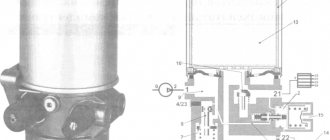
The main element is the boiler compartment, which consists of 4 durable cylinders that form a heat exchanger. This part includes 2 cavities that facilitate the unhindered passage of exhaust gas and coolant circulation. There are 3 tubes on the outer part of the engine heater, 2 of them are intended for draining or supplying antifreeze, one is for exhaust gas removal.
Pre-heater device
The exhaust gases hit the damped part of the boiler, which due to this action change direction and flow to the outlet pipe. In this case, thermal energy is consumed for heating in the engine sump.
On the reverse side, at the open end of the boiler compartment, a burner is mounted, which includes:
- spark plug;
- nozzle;
- valve;
- fuel heater;
- gas heater.
Method 2: regular drainage of return flow (within flow rates)
How this is done: a small diameter hose is built into the return fuel line and connected to the canisters without disconnecting the line itself.
How to determine a failure: the monitoring system automatically records increased consumption, however, it slightly exceeds the norms for this type of equipment. The mechanic’s task is to determine the reasons for the increased consumption through a visual inspection and find skillfully hidden fittings, canisters, cavities - where and how the fuel is drained.
Device
KamAZ on a Cummins engine: the power unit includes the following systems and elements:
- cylinder block;
- cylindrical block heads;
- camshaft equipped with a chain drive;
- injectors that are controlled by solenoid valves;
- turbocharging system, which is equipped with turbines of various models;
- closed-loop cooling system and Bosch fuel system.
Cooling system
The cooling system is an important element that makes it possible for the engine to operate properly, allowing it to prolong its service life. It is a closed liquid system within which coolant circulates.
The operation of the cooling system is automatically regulated by two thermostats, which determine the temperature of the fluid leaving the engine (normally 75-95 °C), and depending on this indicator, change the direction of fluid flow.
When the heat has been absorbed by the liquid, it is sent further through the tubes, where its temperature is lowered by air currents.
This is exactly the operating principle of the Cummins ISBe series engine cooling system.
KamAZ 65115 with a Cummins engine and KamAZ Cummins 4308 are representatives of the ISBe series.
To ensure proper operation of the cooling system, it is recommended to carry out regular diagnostics. A common failure is wear on the fan belt and pulleys.
The engine cooling system includes parts such as:
- A bypass pipe that leads from the radiator to the expansion tank.
- Connecting pipe that leads from the compressor mechanism to the tank.
- Drainage pipes.
- Water connecting tube.
- Overflow pipe for thermostats.
- Water pump element.
- Outlet pipe elbow.
- Fan.
- Drain system screen.
- Supply pipe for the right row of cylindrical elements.
- Hydraulic clutch switch.
- Thermostat box.
- Vapor-air plug.
Control block
Such a block is used to control the cyclic supply of fuel fluid. The design of this device consists of:
- injector;
- high pressure fuel accumulator;
- camshaft position sensor;
- motor control harness;
- coolant temperature sensor;
- oil temperature and pressure sensor;
- camshaft position indicator;
- high pressure fuel pump;
- fuel fluid temperature and pressure indicator;
- power control system harness.