Drilling tool rotation drive
A vertical shaft (up to 5 m or more in length) - a square or hexagonal profile rod along which a gearbox (for example, a rotator) moves - transmits rotation from a stationary mechanism (gearbox) to a movable one (rotator).
It is used in rotation mechanisms of drilling tools when using schemes with movable rotators with an output shaft. Rotators rotate the drill rod or drilling tool. They come in two types: fixed through (rotary) and movable with an output shaft. The fixed rotator is rigidly fixed at the bottom of the mast, and the drill rod is freely mixed in its hole. The movable rotator is installed on the mast guides with the possibility of free movement along them. The output shaft is rigidly connected to the drill rod or drilling tool.
Fixed pass-through rotators are available in single-stage with bevel or spur gears and two-stage with bevel-cylindrical or spur gear only.
Let's consider the most common stationary single-stage rotator through passage with a bevel gear, used in drilling and crane machines BM-205, BM-202A, BM-302A, BM-305 (Fig. 22).
Rice. 22. Fixed pass-through rotator (BM-302A):
Crankcase 2 houses the driving 29 and driven 18 bevel gears. Gear 29 is mounted on two bearings 27, seated in cup 26, and bearing 30. The splined shank of gear 29 is connected to a splined sleeve 22, ending with a flange, which is connected to the driveshaft of the transfer case.
Gear 18 is fastened with rivets to bushing 19, which is installed in bearings 4 and 14, located in cover 6 and housing 2, respectively. Inside bushing 19, textolite liners 20 are installed in grooves, which contact the drill rod (not shown in the figure) located inside the bushing 19. Gaskets 1, 3, 7, 15, 25, 28 are installed at the joints. From the cardan shaft (not shown in the figure), rotation is transmitted to bushing 22, then to gears 29 and 18, bushing 19 and the drill rod. Lubricant is poured into the rotator through a hole closed by plug 11 and breather 10, which communicates the cavity of the rotator with the atmosphere and eliminates the possibility of increasing pressure in it. To prevent lubricant leakage from the rotator, cuffs 5, 13 and 23 are installed in the cover 6 and flanges 12 and 24.
A dirt cleaner 31 is attached to the rotator from below. In the body of the dirt cleaner 31 there is a glass 32 with a split disk 33, which has a flat spring 34 on the outside and a square ring 35 on the inside. A dirt cleaning bag installed in the glass 32, consisting of rings 40 and a solid disk 39, is pressed against the liner 20 and a split disk 37 with an external coil spring 36. The dirt cleaning bag is clamped by a flange 38, which is bolted to the cup 32 and the crankcase 2.
The rotator is mounted on the machine frame (not shown in the figure) using support 21 with the ability to rotate. The support 21 is rigidly connected with bolts to the crankcase 2. The machine mast is attached to the top of the rotator to the cover 6. The position of the housing 2 and flanges 12 and 16 is fixed with pins 17. The fastening of gears 18 and 29 is adjusted using gaskets 1 and 28, and the clearances in bearings 27 are adjusted with gasket 25.
A movable rotator with an output shaft is used when, simultaneously with rotation, it must transmit reciprocating motion to the drill rod (or directly to the drilling tool).
Rice. 23. Movable rotator with output shaft (MRK-690A and MRK-750T):
The movable rotator used in the MRK-690A and MRK-750T drilling machines (Fig. 23) is a single-stage helical gearbox. Rotation from a vertical square or hexagonal shaft 1, mounted on the machine in bearing supports and receiving rotation from a gearbox (not shown in the figure), is transmitted to a sleeve 8, which has a square or hexagonal internal profile and the ability to move along the shaft, then to a drive gear 9 mounted on the bushing using a keyed connection, and then the idler gear 7 and the driven gear 6, sitting on the output shaft 5.
The output shaft is connected to the drill rod (or drilling tool) by 4 pins 3.
The rotator has the ability to move along guides 2 and 10, rigidly mounted on the mast of the machine.
The rotation of the vertical shaft and at the same time the reciprocating movements of the rotator body, for example, with a rope using a winch (not shown in the figure), are transmitted to the drilling tool. In contrast to a stationary rotator, a movable rotator with an output shaft experiences not only circumferential, but also axial reaction loads from the drilling tool.
Source
Before the advent of this machine, otherwise known as a hole drill, the development of holes for the installation of poles for the widest possible purposes was carried out, at best, with a hand-held hole drill. And as a rule - with a shovel. And here comes joy for all those with calloused hands - in the second half of the 1960s, a simple, reliable drill BM-202 appeared, on a wonderful GAZ-66 chassis, and even with a crane with a lifting capacity of 1250 kg, and a little later, BM-302, with a drilling depth of 2 and 3 m, respectively, and a drilling diameter of up to 800 mm. No explanation has been found for why such a popular vehicle, but on a more mobile and cross-country tractor chassis, appeared only in the late 1970s. These were BM-204 hole drills based on MTZ-52 and BM-251 based on DT-75S2. They were replaced by BM-205 (205B, 205V) hole drills on MTZ-82 (MTZ-82.1) and BM-305 on DT-75MV, which are in various upgrades, but without fundamental design differences (except for the installation of hydraulic drives at the turn of the 2000s rotation of drilling tools and crane equipment instead of mechanical ones, models 205D and 308), were produced at least in 2022. There is no doubt that this design will survive on the market until its 60th anniversary.
Manufacturer: Plant of construction and road machines, since 1992 OJSC "Stroydormash", Alapaevsk, Sverdlovsk region. Founded at the end of 1941 on the basis of the Alapaevsk City Industrial Plant and the Scientific Research Institute of Engineering Equipment of the Red Army, evacuated from the Nakhabino station in the Krasnogorsk district of the Moscow region, with a pilot plant subordinate to it.
In 1956, the plant was transferred from the subordination of Glavvoenstroy of the USSR Ministry of Defense to the Ministry of Construction and Road Engineering and the first drilling and crane machine was produced - BKGM-AN-63.
In the 1990s, both the Mikhnevsky RMZ and the Belarusian Amkodor joined the production of these units.
Drilling machines in construction are used to drill wells for the purpose of installing power and communication line supports, road sign posts and fences, and constructing columnar foundations. Machines with lifting equipment for lifting and installing supports, pillars and piles into the well are called drilling and crane machines. These machines can be used in thawed and frozen soils of categories I-IV that do not contain large solid inclusions: stones, boulders, construction waste.
Rotary drilling machines are the most widely used. The main components of their working equipment are: a drilling tool (drill), which directly destroys the soil and brings it to the surface when developing a well; a drill rod that transmits rotation and axial load to the drill; a rotator that ensures rotation of the drill rod with the drill; a feed mechanism that carries out axial movement of the drill rod with the drill; a mast designed to guide the rod during the drilling process, receive the reactive torque from it and place rotation and feed mechanisms on it; a lifting mechanism for carrying out hoisting operations with a drill, a rod, as well as with various loads when performing preparatory and final work.
The most advanced in the 1990s were the cyclic machines BM-205, BM-305, BM-202 and BM-302, which had standardized drilling and crane equipment. A feature of this equipment is the combination of the functions of the feed mechanism and the drill rod in one unit , placed inside a tubular mast and called a hydraulic drill rod.
The hydraulic drill rod is a long-stroke, double-acting hydraulic cylinder, into the cavity of which the working fluid is supplied through internal channels in the hydraulic cylinder rod. The hydraulic cylinder body is made along the outer surface with a square cross-section and has the possibility of both translational and rotational movement relative to the rod, fixed at the upper end inside the tubular mast. A blade drill is attached to the shank of the hydraulic drill rod passing through the through hole of the rotator sleeve.
The rotator of the unified equipment is a single-stage bevel gearbox attached to the lower flange of the tubular mast and driven from the base machine engine through a mechanical transmission.
The compactness and simplicity of the design of this equipment made it possible to reduce the weight of the machines, increase reliability and improve operating conditions, maintenance and repair.
The drilling and crane machine BM-205, according to the principle of operation, is a mechanical drilling machine with forced supply of the drill into the face and with centrifugal periodic unloading of the drill from the ground. The machine is mounted on a MTZ-82L all-terrain tractor with a power of 59 kW and is characterized by high productivity, high speed, maneuverability and efficiency.
The drilling and crane machine includes a base tractor, transmission, drilling equipment, drilling tools, bulldozer equipment, controls, electrical equipment, hydraulic system. The machine is equipped with three replaceable drills equipped with cutters and drillers reinforced with hard alloy, cutting edges for drilling thawed soils and hard alloy plates for soils with seasonal freezing. The drill body is screw, two-thread. The valves hold the soil when the drill is removed from the hole. The drill is driven by the engine of the base tractor through a mechanical transmission and hydraulic system.
Scope of use of the pit drill
The main purpose of the BKM-317 hole drill is vertical drilling of holes in unfrozen soils of categories 1-4 for:
BKM-317
- installation of power line poles;
- arrangement of pile fields;
- installation of pipelines;
- installation of enclosing structures, road signs;
- tree planting;
- other needs of public utilities, construction and energy industries.
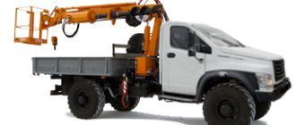
Drilling and crane machines BKM-317 are multifunctional and combine the capabilities of a drilling rig, a crane and an aerial platform. Simultaneously with drilling, the unit can install supports and metal structures. Permissible temperature conditions for operating the machine: -40…+40 degrees.
Purpose of the hole drill
The equipment is designed for drilling holes of various diameters and depths. Used when performing the following types of work:
- laying pile foundations;
- installation of poles (fence or power lines) and any vertical structures;
- planting trees and shrubs;
- construction of wells;
- soil sampling;
- search for shallow water layers.
Additionally, a tractor with a hole drill can be equipped with brushes, dumps, winches, etc., which allows you to effectively solve related problems without the use of additional equipment. For example, perform loading and unloading operations, transport excavated soil or fill trenches.
Yamobur is used in the construction industry
Principle of operation
The basis of any drill is a steel rod with a pointed tip and a helical blade. The tip facilitates deepening into the ground, and the screw blade ensures the removal of soil when lifting the drill. The drill is deepened with rotational movements, the blade cuts the ground, after which the drill is pulled out along with the soil. The diameter of the hole is equal to the diameter of the blade.
The higher the screw part, the less often you need to lift the drill, but the higher its weight and, consequently, the load on the equipment. For MTZ-82, the maximum drill length is 3 m, diameter is 80 mm.
Specifications
The unit is self-propelled and is available in 3 configurations, distinguished by indexes 01, A-01 and 03. All of them:
- Mounted on the chassis of a GAZ-33081 vehicle.
- They have a hydraulic rod feed.
- Capable of drilling wells 3 m deep and 36-80 cm in diameter.
- With effort:
- feed during drilling - 24.5 kN;
- when lifting the drill - 31.65 kN;
- Weight - 6.3 tons.
Drilling and crane machines BKM-317 (corresponding to brands 01, A-01, 03) are distinguished by technical characteristics:
- The torsion moment on the drill is 4.9, 5.9 and 4.9 kNm.
- The method of transmitting rotation to the drill is mechanical, hydraulic, mechanical.
- The angle at which the mast is installed for work is 80-95°, 60-95° and 80-95°.
- The speed at which the drill rotates:
- for cars with index 01 and 03 - 109.1 and 150.6, 189.5 rpm;
- for A-01 - 52-130;
- A lifting device with a mechanical drive capable of lifting a load:
- weight - 1.25, 2.0, 1.25 tons;
- to a height of 6.3, 6.5 and 6.3 m.
Drilling machine BM-205D (BM-205V) based on the MTZ 82 tractor
Peculiarities
The BM-205 drilling and crane machine is very maneuverable, has excellent maneuverability and small dimensions, due to which it is characterized by high productivity. This drilling equipment is a drilling and crane equipment manufactured on the basis of the Belarus MTZ-82 (MTZ-82P) tractor chassis. Yamobur BM-205 is reliable, economical and has low operating costs. Drilling is carried out using the rotational method, reaching a depth of up to 3.0 meters.
Optional equipment
If necessary, BM-205 can be equipped with a fastening device - DRU-01 or lifting equipment DPO-0.
The release device is used to level a support lowered into a previously prepared well immediately before backfilling. In addition, it ensures its stability and holds (secures) it in a vertical position. DRU-01 has proven itself in operation, and, in addition, it is easy to operate. Thanks to the quick-release connecting part, the device is very easy to remove or attach to the equipment.
The DPO-01 lifting device is an auxiliary hydraulic cylinder used for pulling previously installed piles, pillars and supports out of the ground for their reuse in other construction.
Spare parts for BM-205D (BM-205V)
We offer a large selection of spare parts for all modifications of the BM-205 drilling and crane machine. Almost all spare parts are always in stock; for questions regarding purchase and delivery, please contact our sales department experts by phone.
Drill rods
Frame
Frame with control panel and outriggers
Power take-off (PTO)
Rotator
Transfer case
Currently, the production of two configurations of BM-205 has been launched - these are BM-205V and BM-205D. The BM-205V hole drill is equipped with a mechanically driven rotator and is produced with a two-meter or three-meter drill rod. And the BM-205D drilling machine has a hydraulic drive for rotating the drilling tool and a three-meter drill rod. BM-205V and BM-205D can be manufactured with both dump and loading equipment. The blade equipment (bulldozer blade) has dimensions of 2100 mm by 8000 mm - width and height, respectively, with a weight of 410 kg. The predominant cutting angle is 55 degrees. The depth below the tractor support (wheels) should not exceed 0.1 meters, and the rise above it should not exceed 0.5 meters. Loading equipment (front loader bucket) for working with a load weighing 750 kg and a capacity of 0.4 m3 can be raised to a maximum height of 2.6 m, and the width of the cut edge is 1600 mm.
How does BKM-317 work?
The BKM-317 drilling and crane unit is installed on the chassis of a GAZ-33081 truck, which provides high maneuverability and maneuverability of the equipment in densely built-up and off-road conditions.
The machine's cabin is designed with a single-row or double-row seating arrangement, which allows the work crew to be delivered to the site without the involvement of additional transport. The main working body is a bladed drill.
Modifications of the BMK-317 machine are offered in two configuration options:
Supports and drill BKM-317
- with a hydraulic feed drive and a mechanical drive for rotating the drill - the mechanics are unpretentious in maintenance, have a high endurance reserve, but provide only three rotation speeds of the drilling equipment;
- with hydraulic drive of all working parts and systems - with the help of hydraulics, stepless speed control occurs, which significantly reduces the load on the engine and transmission and preserves the life of these most important machine components.
Additionally, the BMK-317 is equipped with a reverse-type winch, used for installing supports into holes prepared in the ground and other crane manipulations. It is possible to install an ADU (additional securing device), which ensures the safety of installers when performing high-altitude work on dilapidated support elements.
The guard rail ensures operator safety. A metal ladder provides convenient access to the main units and components of the drilling and crane machine.
Design features of BKM 317
The BKM 317 drilling unit is capable of drilling straight and inclined wells with a depth of up to 3 m and a diameter of up to 800 mm. The hole drill is equipped with a blade-type drill. The moving parts of the drive are located on the mast of the model structure. It serves as the basis for the crane mechanism and other replaceable equipment - pile driver, manipulator. The mast is enclosed with a grill to enhance operator safety and protect equipment.
The drilling crane machine is available in different modifications:
— the cabin configuration can be single-row or double-row;
— the drill rotation drive can be mechanical or hydraulic;
— different ranges of mast tilt angles;
— the type of crane drive can be mechanical or hydraulic;
- different lifting capacity of the crane.
Depending on the design features of the machine, prices can vary significantly. More expensive models with hydraulic circuits can offer better drilling technological parameters, a convenient control system, and more rational use of the transmission and engine capabilities. The presence of hydraulics and a regulator with a wide range of rotation speeds allows you to select a faster and more optimal drilling mode for a specific soil type and its density. The following design features of the BKM 317 hydraulic type can be noted:
— the hydraulic drive of the rod rotation has an automatic torque speed regulator;
— the hydraulic system is made of high quality imported components;
— the metal structures of the crane, supporting frame, supporting elements and some other components are strengthened through the use of closed profiles, additionally welded tenon joints, the use of bending operations instead of welding and the use of other technical solutions;
— an imported hydraulic winch with increased lifting capacity was installed;
— special-design hoses were used, which made it possible to abandon metal pipelines.
The advantages of mechanical machines include ease of maintenance, good endurance, and inexpensive spare parts. However, hydraulic BKMs have a significantly longer service interval.
BKM317 have gained popularity and found wide application throughout the country. They work great with 1-4 grade soils. inclusive, except frozen. The technical performance of a hole drill when drilling a hole 0.5 m in diameter by 3 m in depth is 15 meters per hour. The maximum lifting height of the hook is 6.5 m.
Some other advantages of the drilling and crane unit can be noted:
— excellent off-road capability;
— sufficient maneuverability allows operation in limited areas in densely built-up conditions;
— drilling from the chassis at a safe distance;
— high maintainability in road conditions;
— possibility of retrofitting in relation to current tasks.
Technical parameters (operational indicators)
The performance characteristics of the machine allow you to quickly and efficiently carry out drilling and crane work:
Drill device for BMK-317
- overall dimensions of the basic model BKM-317 (length/width/height) – 7.05*2.5*3.27 m;
- total weight - 5.95 tons;
- wheel formula – 4*4;
- type of drilling – cyclic;
- maximum drilling depth – 3 m;
- well diameter – up to 80 cm;
- drilling angle – 60-95 degrees;
- crane lifting capacity (mechanical drive/hydraulic drive) – up to 1250/2000 kg;
- maximum torque – 4900-5900 (depending on modification).
Purpose and features of pit drills
Pit drills based on MTZ 82 are designed for drilling shallow holes in the ground for the installation of columnar foundations, installation of fence posts, light poles, holes for planting trees, etc. Their characteristic features include:
- small drilling depth, usually equal to the length of the auger drill;
- the use of an auger drilling method using bladed drills of a certain length and diameter;
- the use of additional equipment for flushing or purging during drilling is not required.
Some models of hole drills have auger drills of a telescopic design or the ability to increase their length using additional extensions, which allows you to drill deeper holes.
The NBU-1300 hole drill allows for drilling holes up to 1.3 meters deep with an auger drill with a diameter of up to 360 mm with a mechanical rotator drive.
The BM-205V hole drill with a hydraulic rotator drive is used for auger drilling of wells up to 3 m deep and with a diameter of up to 80 cm.
Device and characteristics
The entire family of Sadko trucks has a frame structure and is equipped with a cabin installed behind the engine. Units designed for 3-7 passengers, built according to a 1- or 2-row design, are used. The machines use a synchronized 5-speed gearbox and a 2-speed transfer gearbox. The transmission allows the installation of a power take-off, which is used when the vehicle is parked and moving.
The car 33081 Taiga has an original design, which was built using body elements from GAZ Valdai.
The vehicle has a 2-row, 7-seater cabin with increased height and a separate metal van, which can be used as a workshop or shift station. The power unit is a Cummins 3.8 diesel engine.
Crane drilling machine frame
The BKM-317 frame is a welded metal structure fixed to the chassis, onto which the working systems and components of the drilling and crane machine are installed:
Frame BKM-317
- mast hydraulic cylinder – for lifting and fixing the mast in working position;
- transfer case with winch - for changing the rotation speed and direction of the drill;
- oil tank;
- cardan shafts - for transmitting rotational motion to BMK-317 drilling equipment;
- hydraulic pump – to drive equipment;
- hydraulic jacks – ensure the stability of the installation during drilling and crane operations;
- control panel - facilitates the process of monitoring equipment and managing technological operations.
The BM-205D drilling and crane machine has the following technical characteristics:
| CHARACTERISTICS | Drilling and crane machine BM-205D |
| Basic chassis | MTZ-82 |
| Drilling depth, m | 3 |
| Drilling diameter, m | 0,36; 0,50; 0,63; 0,80 |
| Load capacity of crane equipment, t | 1,25 |
| Maximum hook lifting height, m | 7 |
| Drilling angle, degrees | 60 — 105 |
| Technical productivity when drilling a well to the full depth and installing a support in it, pcs./hour | 5,3 |
| Maximum torque on the drilling tool, Nm | 4900 |
| Overall dimensions in transport position: | |
| - length | 6800 |
| - width | 2500 |
| - height | 3950 |
| Overall dimensions in working position: | |
| - length | 6590 |
| - width | 2500 |
| - height | 7600 |
| Total weight, kg | 6450 |
| Additional attachments: | |
| Additional fastening device DRU-01 >> | |
| Additional lifting equipment DPO-01 >> | |
| Front Loader Bucket | |
| Double jaw bucket | |
| Bulldozer blade | |
| Load forks | |
Equipment
Frame for placing executive equipment and mechanisms.
It has a welded steel structure and is secured with stepladders to the chassis frame device. The following are attached to it:
- Hydraulic oil container.
- Hydraulic cylinder for mast installation . It is necessary for lifting the drilling mast and fixing it in the working position.
- Transfer case - for transmitting force from the installation engine along the drive shafts of the hydraulic pump, winch drum, and rotary equipment of the drill rod. Provides three speeds of drill rotation, changing the direction of rotation of the tool and reversing the winch.
- A winch with a “worm” drive through cam-type coupling halves, which perform the functions of a safety device for the weight of the load.
- Cardan shafts transmit torque to the rotating device of drilling equipment.
- A gear hydraulic pump on the intermediate shaft of the distribution box ensures the operation of the hydraulic system.
- Outrigger hydraulic jacks mechanize the process of positioning the drilling rig above the drilling point and make the platform stable during cargo operations.
- The control panel allows the operator to control the operation of mechanisms and equipment, and carry out drilling and loading technological operations.
Mast
A mast is a welded metal structure on which are mounted:
- barbell;
- rotary device with hydraulic or mechanical drive . The hydraulic rotation drive increases the service life of the engine and transmission, providing a gentle, shock-free operation of the unit;
- crane device bracket
- welded fencing ;
- metal staircase .
At the top of the ladder in the mast there is an opening for adjusting the sealing device of the rod.
Hydraulic system
Devices and mechanisms of the system provide:
- stepless regulation of the axial movement of the drilling tool, its supply to the bottom of the well and extraction;
- transition of the unit from the transport position to the operating and return cycle;
- installation and control of outriggers.
Which tool to choose
Depending on the density, composition of the soil, and their condition, blade drills of the BK-012 type, cone type BK-02201, and core type B-04201 produced by StroyDorMash OJSC are used as the working tool of the BKM-317 machine.
- Blade drills are the most used type of working equipment for soils from density categories I to IV. The BK-01204 tool is the most universal in the plant’s assortment. Models with indexes 01201, 01203 are effective in weaker soils.
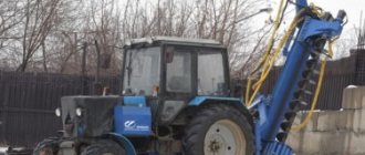
Yamobur NBU-1300 (for MTZ-82)
The NBU-1300 mounted drilling rig is designed for drilling wells in soft soils. The set includes two drills 220 and 360 mm. Installed on the MTZ Belarus-80.1 tractor; - 82.2; - 890.2; - 892; - 920; - 920.2. The drive is mechanical from the tractor PTO.
| Name | Price | |
| Yamobur NBU-1300 (for MTZ-82) with drills 220 and 350 mm. | PC | 266,000 rub. |
| Mounted drilling rig NBU-1300 (without augers) | PC | 212,000 rub. |
| Replaceable attachment tool – drill NBU-1300.45 (auger – 150) | PC | 24900 rub. |
| Replaceable attachment tool – drill NBU-1300.40 (auger – 200) | PC | 25500 rub. |
| Replaceable attachment tool – drill NBU-1300.46 (auger – 220) | PC | 26,000 rub. |
| Replaceable attachment tool – drill NBU-1300.41 (auger – 250) | PC | 26470 rub. |
| Replaceable attachment tool – drill NBU-1300.42 (auger – 300) | PC | 28700 rub. |
| Replaceable attachment tool – drill NBU-1300.43 (auger – 350) | PC | 29940 rub. |
| Replaceable attachment tool – drill NBU-1300.44 (auger – 400) | PC | 33900 rub. |
| Replaceable attachment tool – drill NBU-1300.47 (auger – 500) | PC | 37900 rub. |
| Replaceable attachment tool – drill NBU-1300.48 (auger – 600) | PC | 41,700 rub. |
The mounted drilling rig NBU-1300 (hereinafter referred to as the Equipment) is designed for drilling wells in soft soils.
Technical characteristics of pit drill NBU-1300
| Dimensions, mm | meaning |
| length | 5400 |
| width | 2000 |
| height (in cabin) | 2800±50 |
| Tread, mm | |
| front wheels | 1650±20 |
| rear wheels | 1550±20 |
| The height of the drill lifting above the supporting surface, mm | 350 |
| Drill lifting and lowering drive | hydraulic from the tractor rear linkage hydraulic system |
| Bur rotation drive | mechanical from tractor PTO |
| Maximum drilling depth, mm | 1300 |
| Tractor PTO rotation speed, rpm | 540 |
| Bur rotation speed, rpm | 280 |
| Drill diameters included | 220 mm. and 360 mm. |
| Aggregation | MTZ "Belarus - 80.1"; - 82.2; - 890.2; - 892; - 920; - 920.2. |
| Equipment operating weight no more than, kg | 4400 |
| Weight of attachments, kg | 350 |
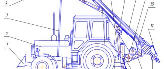
Design and principle of operation of the NBU-1300 pit drill
The NBU-1300 equipment consists of a Frame (item 1, Fig. 1), Gearbox (item 2, Fig. 1), Cardan Shaft (item 3, Fig. 1), mounted replaceable tool (Drill) (item 4 , Fig.1), Protective casing (Pos.5, Fig.1), Adjustment nut (Pos.6, Fig.1), Bracket (Pos.7, Fig.1). The NBU-1300 frame is mounted on the lanyard of the rear linkage of the tractor. The bracket is installed with the lower axle into the arms of the rear linkage. The cardan shaft is connected to the tractor PTO. The torque from the PTO is transmitted through the gearbox to the drill. The cardan transmission has a safety clutch to protect the transmission from overloads; the tightening force of the safety clutch depends on the composition of the soil and the depth of drilling. The adjusting nut is used to set the drill axis in a vertical position depending on the drilling depth. Preparing NBU-1300 equipment for operation.
Carry out a visual inspection of the Equipment, check the threaded connections, tighten them if necessary, eliminate any identified faults, check the presence and condition of oil in the Bura drive gearbox.
When checking the operation and tightness of the hydraulic system, lift and lower the Equipment several times, make sure there are no oil leaks and damage to the hydraulic system pipelines, and eliminate any detected malfunctions. After lifting the Equipment, set the hydraulic distributor lever to the “neutral” position for 2-3 minutes, make sure that there is no spontaneous lowering. Prepare the base tractor for operation in accordance with the “Operation Manual for the Belarus Tractor”. Equipment running-in. The running-in of the base tractor is carried out in accordance with the “Operating Manual for the Belarus Tractor”. Run-in of the Equipment is carried out in two stages:
- rotating the drill for 20 minutes at medium engine speed;
- work at an average load for 30 hours (5 shifts);
After running-in, it is necessary to carry out an external inspection of the Equipment and eliminate any identified faults, check the oil level.
Operation of pit drill NBU-1300.
- ETO must be performed before starting the engine.
- Preparation for starting the engine is carried out in accordance with the “Operating Manual for the Belarus Tractor”.
- Before starting work, check the movements of the working parts at idle engine speed.
- To avoid overloading and equipment breakdown, insert the drill into the ground smoothly, without jerking. Do not overload the Equipment.
- The use of the Equipment for drilling rocky soils and hard road surfaces is not permitted.
- Before starting work, study the scope of the upcoming work and the condition of the soil.
- Set the tractor to the handbrake.
- Using the hydraulic drive of the rear linkage, lower the Equipment until the drill touches the supporting surface.
- Adjust the diagonal position of the Frame using the turnbuckles of the rear linkage levers.
- Use a lanyard and an adjusting nut to adjust the vertical position of the drill relative to the ground, taking into account the drilling depth.
- Adjust the tightening force of the safety clutch taking into account the depth and diameter of the drilling, as well as depending on the quality of the soil. The maximum permissible drilling force is achieved at a distance of 180 mm between the tightening flanges of the safety clutch springs, and is set at the manufacturer.
- Turn on the PTO rotation drive.
- Carry out a smooth penetration of the drill into the soil to a depth not exceeding the equipment’s specifications.
- When the drilling depth is more than 700 mm, periodically lift the drill from the hole and clean it. If there are difficult-to-pass and viscous inclusions and layers in the soil, the lowering speed of the drill and the tightening force of the safety clutch springs should be minimal.
Moving to the place of work.
- It is recommended to move to the work site under your own power only over short distances.
- When moving, the Equipment must be brought into transport position.
- It is prohibited to drive at a speed of more than 5 km/h on roads that have a large side slope, large uneven spots or sharp turns.
Equipment hydraulic system
The BMK-317 hydraulic system is designed for:
- transferring the drilling unit from the transport position to the working position;
- stepless transmission of reciprocating motion of the executive body and its supply to the bottom of the well;
- control of hydraulic jacks.
Adjustable hydraulics allow you to select the optimal drilling mode, depending on the task and soil characteristics.
Trench cutter on BKM-317
Drilling and crane machine KAMAZ-43118 with BCU HTMI-086A
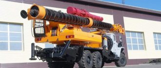
The main quality that is valued in BKM is the versatility of their application. The most popular in this regard is the KAMAZ-43118 model, equipped with its own design - the HiTECH MACHINERY (HTMI) 086 drilling and crane rig.
The onboard version of the car is used as the chassis here. Thanks to this, the BKM of our production can be used in dense urban areas, on rough terrain or in the forest. The popularity of the KAMAZ-43118 drilling and crane machine with the HTMI-086A BCU is easy to explain: with it you no longer need to maintain several types of special equipment. Just one such a BKM will cope with drilling for various tasks, and with the installation of supports, and with the transportation of goods. Using our BKM you can screw in screw piles.
It allows loading and unloading. A certified mounting basket is useful for high-altitude work and maintenance of network infrastructure facilities.
One of the main advantages of this version of the KAMAZ-based BKM is the reliable HTMI-086A drilling and crane rig. We developed and manufacture it ourselves. The technological solutions of SDM-KARAT are based on requests from clients from different fields of activity and a thorough knowledge of all operational difficulties that can only be encountered in the Russian open spaces. And the quality of our installations is confirmed by the reviews of dozens of specialists from different parts of the country, for whom the KAMAZ-43118 with the HTMI-086A BCU has become an indispensable assistant in construction and installation work over the years.
Key advantages of the model:
• Powerful frame - especially for high loads • reinforced column rotation gear • 300-330 hp engine. and a 9-10-speed gearbox;• interaxle and cross-wheel locks;• restyled cabin (with or without a sleeping bag, depending on the model);• emissions comply with Euro-5, there is an exhaust gas neutralization system;• load capacity of the onboard platform is up to 12.7 tons.
• Rotator with a power of up to 12000 nM • boom type - hexagonal; • 6 sections; • 360 degree rotation;
• drilling equipment on the third boom extension; drilling to a depth of up to 15 m. • maximum auger diameter - 1 m, • drilling radius relative to the frame - up to 10 m;
• rotating bunk on board; • maximum load capacity - 8 tons; • maximum lifting height - 23 meters; • cradle with dielectric adapter as standard; • possibility of installing an AGP sensor.
Types of hole drills
Drilling equipment for wheeled tractors is divided into two large groups:
- Pit drills themselves, designed for drilling wells up to 3 m deep using the “dry” method (without cleaning). In this case, a conventional, extendable or telescopic drill can be used.
- Drilling and crane installations are used to construct wells up to 20 meters deep.
- They are equipped with a lifting mechanism, which allows you to work with a large volume of excavated soil.
Be sure to read: Technical characteristics of YaMZ 236 Turbo
According to the type of working tool, drilling mechanisms are divided into:
- Shock-rope. The design is based on a bailer. It is made from a round hollow steel pipe with a diameter of 80-120 mm and a length of 50-100 cm. A metal handle is welded at one end, and a metal or rubber valve is installed at the other. The bailer is fixed to a frame with a winch and lowered into the well under the influence of gravity. When the bottom is reached, the valve tongue opens, the bailer captures part of the soil, after which it is lifted up. The valve tongue closes, keeping the soil inside.
- Screw. Most hole drills belong to this type. They are steel pipes with a screw belt with a diameter of 100-200 mm and a length of 2 m. When the auger rotates, the soil rises outward along the thread. As the drill deepens, it is expanded by adding metal rods.
- Rotary. They provide drilling with simultaneous washing out of soil. The drill is equipped with special carbide bits. Motor pumps are used to supply water.
- According to the type of soil being cultivated, drills are distinguished for soft soil, hard and rocky soil.
The last two relate to professional equipment. However, owners of personal tractors more often deal with soft soils: black soil, sand or clay. In such conditions, you can get by with a homemade or inexpensive ready-made drill.
Devices are divided into types depending on operating conditions
Popular models
The most popular model of drilling machine in the post-Soviet space was the BM-205D. It is this that is installed on the basis of MTZ-80 (82) tractors in most cases. There are three modifications:
- BM-205D -01 (with loading device);
- BM-205D-01 (with a blade for removing snow and soil);
- BM-205V (with a blade for snow removal).
For smaller-scale work, NBU-1300 is widely used. This is a compact drill that is connected to the tractor PTO like a conventional attachment. Models from such manufacturers as MTZ, AgroMax, Wirax, AgroTehKomplekt have also proven themselves well.
Be sure to read: Technical characteristics of ROU-6
If the budget is limited, and the owner of the tractor has extensive experience working with metal and has excess material, it is worth asking how to make a hole drill for a tractor with your own hands. It often happens that there is an unnecessary auger drill lying in the garage or workshop. If not, you can make it yourself from a thin pipe and blades cut from a steel sheet.
The simplest option for semi-manual drilling is to attach a hydraulic motor to the auger, which is connected with hoses to the hydraulic system of the tractor. The auger is equipped with two long handles that workers hold onto. The design is very simple, but it only works when drilling to a depth of 20–30 cm and preferably on light soils.
For more serious work, you will need to assemble a structure from an auger drill, pipes and an automobile gearbox from the rear axle (suitable for Moskvich, UAZ, Lada). In this case, drilling is carried out without assistants, using motor power alone. If you make such a hole drill with your own hands on a tractor, the average drilling speed will be about 2 m in 5-10 minutes.
It is important to completely remove any remaining soil from the auger. It is also recommended to remove the cross between the drill and the gearbox for a more rigid and reliable fixation.
Before starting work, you should carefully study the technical characteristics of the tractor so as not to overload its body and chassis. It is also useful to familiarize yourself with videos and example drawings, which are easily found on the Internet.
You can buy a drill or make it yourself
Types of drills for BKM-317
Depending on the type and properties of the soil, various types of drills are used for BKM-317:
- bladed - most common for weak and dense soils;
- conical - with replaceable round teeth (for processing rocks, including marble and limestone);
- core - for working on hard rocks.
The GAZ-based drilling and crane machine is characterized by high maneuverability and unpretentiousness. The build quality and technical characteristics allow the equipment to be used in difficult working conditions. Unified spare parts and components provide a high degree of maintainability. The ability to select the optimal mode and additional crane equipment make the machine universal for a wide range of drilling operations with various types of soil.
Modifications
BM-205D is manufactured on the basis of MTZ-82, 82P and 92P tractors. Depending on the modification, the machine can be equipped with a blade or a loader bucket. Thus, the machine can be used when planning construction sites, for filling trenches/pits, loading and transporting bulk materials.
| Equipment designation | Equipment |
| BM-205D | MTZ-82.1 base with bulldozer blade |
| BM-205D-01 | MTZ-82.1 base with front loader bucket |
| BM-205D-02 | Belarus-82P base with bulldozer blade |
| BM-205D-03 | Belarus-82P base with front loader bucket |
Scheme
The machine consists of a basic wheeled tractor and attachments mounted on it.
1 — Blade device, 2 — Basic tractor, 3 — Support stand, 4 — Lifting equipment, 5 — Controls, 6 — Radiator, 7 — Mast hydraulic cylinder, 8 — Drilling and crane equipment, 9 — Hoist winch, 10 — Lighting headlight , 11 — Chains with carabiners for fastening drilling tools in transport position, 12 — Drilling tools, 13 — Frame, 14 — Hydraulic jack, 15 — Chains with carabiners for fastening hydraulic jacks in transport position, 16 — Pump drive.
Source
Leave a request in any form
The Belarus 82.1 wheeled tractor is used as a base for installation of drilling and crane equipment. The design description is set out in the operating manual for this tractor.
Frame 2
drilling and crane equipment (Figure Installation of equipment on the frame 1.4) is a welded metal structure and is attached to the base tractor through bracket 1 to the front beam and bolts 4 with nuts 5 to the sleeves of the tractor axle shafts.
The following are installed on the frame:
- control panel for drilling and crane equipment 9;
- battery box 3;
- a transmission consisting of a transfer case 7 with a winch 10 and a clutch 13, a cardan shaft 6 connecting the tractor power take-off shaft with the transfer case and a cardan shaft 15 connecting the transfer case with the rotator;
- transfer case control 8;
- lifting equipment 14;
- hydraulic lift 11;
- hydraulic jacks 12.
Mast 4
(Figure Installation of equipment on a mast BM-205V 1.5, Installation of equipment on a mast BM-205V-01, BM-205V-02 1.6) is a welded metal structure. The mast is installed in the frame brackets on axles 9 with nuts 10. The mast is equipped with a bracket for fastening the hydraulic cylinder for lifting the mast, an indicator of inclination and drilling angle 3. Crane equipment 6 is installed on the mast, having a boom, for installation of which a hydraulic cylinder 5 is used to install it in the working or transport position. To protect the tractor and protect the driver when installing supports on the mast, a guard 8 is provided.
Inside the mast 4 there is a drill rod 1, at the output end of which a drilling tool is installed. There is a window 7 in the upper part of the mast for adjusting the drill rod seals; a rotator 2 is attached to the lower flange of the mast.
Drive mechanisms
drilling and crane equipment is carried out from the engine of the base tractor using a mechanical transmission. The basic kinematic diagram is presented in the figure. Basic kinematic diagram 1.7.
Power supply for electrical equipment
carried out by direct current 12V from the base tractor network using a single-wire electrical circuit.
The type and characteristics of electrical equipment are given in the table
Type and characteristics of electrical equipment 1.4. The electrical circuit diagram of the attachment is shown in the figure. Electrical circuit diagram 1.8.
Table 1.4 Type and characteristics of electrical equipment
| Positional designation | Name | Col. |
| G1, G2 | Rechargeable battery 6cm-90A TU 16-563.043-86 | 2* |
| Switching devices | ||
| S1 | Ground switch 1212-37-37-04 | 1* |
| X1 | Panel 15.3723 | 1* |
| X2…X8 | Single-pin plug connection OST 37.003.032-88 | 4 |
| M1 | Starter AZJ 3124 | 1* |
| Lighting | ||
| EL1 | Rear left lamp 73.03.3716 TU RB 600124825.026-2002 | 1* |
| EL2, EL5 | Headlight “BEL-FER” TU RB 28927023-2002 | 2* |
| EL3, EL4 | Headlight 8724.3 | 2* |
| EL6 | License plate light FP 131 AR | 1* |
| *Included with the tractor. | ||