Incomplete gear disengagement or clutch slipping can lead to premature wear and failure of clutch parts, front and rear axles, and gearbox. The technical condition of the clutch and its serviceability can be determined by certain signs that characterize you or another malfunction.
Clutch faults
| Clutch does not transmit full torque | No pedal free play | Adjust pedal free play |
| Driven disc linings are worn | Replace the driven disk assembly | |
| The clutch does not disengage completely | Increased pedal free play | Adjust pedal free play to normal value |
| Oil ingress into dry clutch compartment | Wear of the cuff sealing the crankshaft | Replace the cuff |
| The bearing cover of the driven shaft of the PTO drive was pressed out when docking the tractor after repair | Install a new cover or remove the old one | |
| Wear of the cuff of the lifting bracket | Replace the cuff |
Breakage or wear of clutch parts is usually accompanied by the appearance of suspicious knocks and noises, clutch slipping and difficult gear shifting. If a whistle or increased noise appears when you press the clutch pedal, this indicates the destruction of the release thrust bearing.
If the clutch drive is incorrectly adjusted, which is characterized by a lack of clearance between the pressure levers and the thrust bearing, the bearing rotates constantly, which causes it to overheat, leak out lubricant and, ultimately, lead to bearing failure. In most cases, when a faulty bearing jams, the contacts of the pressure levers also burn out.
A decrease in the force of the pressure plate springs can lead to a decrease in the traction force of the MTZ 82 tractor, slipping of the clutch, and a decrease in the rotation speed of the power take-off shaft.
During operation of the tractor, the linings wear out, the driven clutch discs warp, and the rivet heads cause serious annular marks on the surface of the pressure plate. Due to increased heating, cracks and discoloration may form on the working surface of the pressure plate.
Clutch slipping usually occurs as a result of oil getting on the surfaces of the discs caused by leaks through the crankshaft seals or gearbox shafts.
If the release levers are incorrectly adjusted (the ends of the levers are placed at different heights) or the driven disks are warped, the gears shift with some difficulty. In this case, a misalignment of the pressure plate occurs when the clutch is disengaged - the edges of the driven disk are clamped between the flywheel and the pressure disk, as a result of which the clutch “drives.” Difficulty shifting gears can also result from the hub splines sticking on the clutch shaft splines due to their gradual wear.
Disassembly and removal of the clutch
Before dismantling the clutch, it is necessary to screw special technological bolts into the flywheel to pre-compress the pressure springs and unscrew the bolts securing the support disk, and then the technological bolts. Before disassembling the clutch, mark the housing and pressure plates, taking care to ensure the correct placement of parts during assembly and maintain the original balance of the clutch.
The clutch is disassembled using a special tool.
Dismantling the support and pressure disks:
1 - two-jaw puller; 2 — support disk; 3 - technological bolt.
Removing the clutch:
1 - clutch;
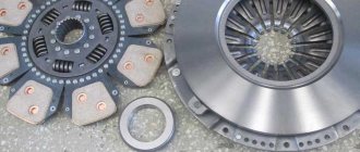
2 - technological bolt; 3 — bolt securing the support disk. If the thickness of the driven disk is less than the permissible values, then it is necessary to replace the friction linings or the entire disk assembly. After replacing the friction linings, the sinking of the rivet heads should be at least 2.0 mm. The pads should fit snugly to the disc; Leaks up to 0.1 mm are allowed. If the thickness of the driven disk corresponds to the norm, and the heads of the rivets are buried below the plane of the lining by 0.1 mm or less, then both friction linings should be replaced.
Inspect the general condition of the pressure plate. No traces of burns are allowed on its surface; cracks occupying more than 40% of the surface; ring marks more than 0.2 mm deep. The working surface of the pressure plate is corrected by turning or grinding until signs of wear are removed.
Clutch replacement
The clutch is assembled using a special device (see figure above). It is necessary to compress the pressure plate springs and screw in the technological bolts in order to fix this position. A process shaft is mounted in the inner race of the flywheel bearing, which is necessary for the correct mutual installation of the splined hubs of the driven disks and creating their alignment with the flywheel.
Centering the driven disk:
1 - process shaft;
2 - support disk. Adjusting the clutch of the MTZ 82 tractor
The free play of the clutch pedal is adjusted by rotating the rod. In the released position, the pedal lever should rest against the cabin floor. If it does not rest, gradually unscrew the thrust bolt from the bracket. If such adjustment is not enough, then it is necessary to loosen the bracket fastening bolt and turn the bracket towards the spring clockwise.
With the clutch release mechanism correctly adjusted and the size 12±0.5 mm being observed, the gap between the thrust bearing and the protrusions of the levers should be 3±0.5 mm.
Adjusting the clutch paws:
1 — release lever;
2 - technological shaft. Brake adjustment is carried out in two stages.
This is the first: 1. Disconnect the rod from the bracket; 2. Turn the bracket to the right counterclockwise until it stops; 3. By rotating the fork, increase the length of the link until the bracket and fork are freely connected.
Stage two:
1. Rotate the fork until the total length of the rod is reduced by 7 mm; 2. In this position, connect the fork to the bracket; 3. After adjustment, secure the fork with the lock nut.
Repair of tractor clutch MTZ 82
If, while the tractor is operating, you hear the grinding of gears that appears when changing gears, this indicates improper adjustment of the clutch control mechanism and wear of its discs, wear of the surfaces at the junction of the brake release pin and fork, wear of the brake and friction discs.
If, by troubleshooting the clutch and adjusting it, it is not possible to eliminate the grinding of gears, then it is necessary to adjust the brake spring tension mechanism. In a correctly adjusted brake control mechanism, the length of the compressed spring is 31-32 mm. If this adjustment does not solve the problem, then you should remove the cabin floor, the cover of the upper hatch of the clutch basket and the reduction gear, and then measure the thickness of the brake disc linings. If the thickness of the linings is less than 1.5 mm, the brake disc must be replaced.
To replace, disconnect and roll out the tractor frame, disconnecting the clutch housing from the gearbox, remove the reduction gear control cover; Using technological bolts, remove the clutch shaft and replace the brake drive disc.
Removing the control mechanism for the reduction gearbox and gear coupling:
1 - control mechanism;
2 — clutch shaft. Large free play of the clutch pedal, which cannot be adjusted, indicates wear of the grooves of the shift forks and the surfaces of the shift pins. In order to determine the level of wear of this coupling, it is necessary to disconnect the clutch basket from the engine and measure the gap between the lift pins and the forks. If the gap is 2 mm, then the taps and plugs must be replaced.
The clutch of the MTZ-82 tractor, just like that of other vehicles, is designed to transmit torque from the engine to the transmission
.
Moreover, this transmission is not rigid, since there are moments in operation when it needs to be turned off: - when starting the engine in the cold season, so as not to rotate the gearbox with the starter; - when starting smoothly; - when changing gears, to stop the rotation of gears on the input shaft in the box. The MTZ-82 tractor clutch is dry
, with one friction disc, constantly engaged due to springs. Located in the housing connecting the engine to the gearbox. The clutch is engaged and disengaged using the pedal.
Recommendations for installing LuK clutch kits on MTZ-80/82 tractors
Recommendations for installing LuK clutch kits
art.
No. 633308709 / 633308710 for MTZ-80/82 tractors. To eliminate risks, it is recommended to use a rail system to “roll out” the tractor engine and transmission when replacing the clutch system to prevent damage to the driven disk. A beam crane with a large pitch when controlling the lifting height is not suitable for these purposes!
Before installing new clutch system parts, you must perform the following steps:
- After cleaning the gearbox input shaft, make sure that there is no critical wear on the spline part. Test method: a new clutch driven disc installed on the input shaft for testing should not have difficulty moving on the splines and should not have excessive play.
- It is recommended to replace the gearbox input shaft oil seal by removing the guide sleeve and simultaneously monitoring the wear of the input shaft support bearing. If obvious signs of wear on the guide bushing and bearing are detected, replace the parts!
- When removing the shaft with the release bearing drive forks, pay attention to the wear of the mechanical contact points of the parts. If there is wear, the drive shaft with forks must be replaced. Be sure to apply high-temperature grease to all metal-to-metal friction pairs of the clutch release system and the splined connection of the input shaft, removing excess.
Attention!
Too much lubricant on the splines of the gearbox input shaft and the clutch driven disc leads to its contact with the friction linings during tractor operation and their damage!
- Before installing a new clutch, check the flywheel for wear, absence of signs of overheating and microcracks. If the technical condition of the flywheel allows its continued operation, clean the friction surface with medium-grain sandpaper, thereby getting rid of the so-called “polished” surface.
- Clean the transmission bell from contaminants and eliminate the causes of their occurrence.
- Clean the friction surfaces of the flywheel and clutch pressure plate from dirt or preservative grease.
Installation of the clutch driven disc must be carried out in accordance with the designation on the hub (FW/side - Flywheel side - flywheel side)
using a centering mandrel.
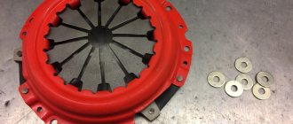
Tighten the pressure plate housing strictly according to the “star” pattern, observing the tightening torque specified in the tractor repair instructions. Do not remove the transportation brackets (3 pcs.) until the clutch housing is screwed onto the flywheel. These elements will separate on their own when the clutch nuts are fully screwed onto the studs.
Before installation, the original MTZ release bearing must be injected through the fitting with the lubricant specified by the tractor manufacturer. The release bearing from LuK is maintenance-free and pre-lubricated.
When “rolling” the tractor, ensure maximum alignment of the gearbox and internal combustion engine and eliminate shock loads on the splines of the driven disk when connecting the transmission.
After assembling the tractor, ensure free play of the clutch pedal in the range of 40 - 45 mm, as well as a gap of 3 mm between the release bearing and the diaphragm spring pins.
The maximum resource during operation is achieved only with a one-time replacement of all wear elements of both the clutch system and the clutch release system.
Source
Device
The transmission of the MTZ 82(80) tractor is equipped with a dry single-disc friction mechanism that is constantly closed.
The unit is installed in a separate dry compartment of the cast-iron housing of the intermediate part of the transmission and is attached with its casing to the engine of the machine. The mechanism interacts with the transmission through shaft 13, on which a clutch basket is installed, consisting of a thrust, pressure and driven friction discs. Stamped support disk 10 with slots for thrust spring cups 9, holes for mounting release levers 3, as well as holes around the perimeter for attaching the unit to the engine drive flywheel 1. In the center of the part, a splined hub is secured with rivets.
A cast pressure disk with a ground working surface for effective connection with the friction linings of the driven disk is installed under the thrust disk. The reverse side of the part is equipped with eyes for attaching the squeezing feet. The three fastenings are located symmetrically with the same angle of 120 ̊ from each other.
The release levers are spring-loaded by return springs and are pivotally connected by pins in the pressure plate mounts. To install the working surfaces of the levers in the same plane, the position of each lever is adjusted with screw 4 and fixed with a lock nut. The position in the same plane ensures uniform simultaneous disconnection of the surfaces of the pressure 11 and friction driven disc 2 without distortions, eliminating uneven wear and incomplete disengagement of the clutch. The uniform fit of the planes of the part is ensured by thrust springs 9, which are installed in the cups of the thrust disk 10.
The driven friction disk 2 is equipped on both sides with riveted friction linings with radial slots for ventilation. Between the pads and the disc itself there are six leaf springs on each side. This connection of the linings with the part allows you to absorb the increasing load during the working connection with the flywheel when the clutch is smoothly engaged. Eight damper springs 14 or rubber bands are placed around the spline hub of the part, which smooth out changing dynamic loads in the transmission when turned on.
The release bearing 5 is installed on the mechanism shaft and with its working surface presses the release levers of the assembly. The movement of the bearing is carried out through the interaction of the leads with the fork of the mechanism drive.
Installation of clutch on tractor MTZ 82, MTZ 80
- The clutch disc must be installed correctly. It is installed specifically on one side in relation to the flywheel
- It is necessary to center the disc relative to the clutch using a special mandrel
- The position of the push levers needs to be adjusted. So that they are at a certain distance from the plane of the clutch disc. And they evenly fit along the plane to the release bearing. So that there is no distortion of the basket pressure plate. Otherwise, the tractor will jerk when starting.
Installing the clutch disc on the MTZ 80.82 tractor
As you can see in the drawing, the disk is installed in this way. So that the long part of the splined hub faces the engine flywheel. This is an important condition, otherwise the secondary shaft of the gearbox will rest against the splined part of the disk and the gearbox will not be able to get into place.
Installing the clutch basket
To install the clutch basket onto the flywheel. A special mandrel must be used. It is inserted into the slotted part of the basket. The clutch disc is put on it. Thus, as mentioned above.
So that the long spline part faces the flywheel. In this state, the clutch basket together with the disc is installed on the flywheel and screwed with mounting bolts. It is necessary to screw evenly. In this case, it is constantly necessary to move the mandrel in different directions. So that it does not become pinched during final tightening of the mounting bolts. After the basket is completely screwed. It is necessary to adjust the clutch basket feet.
Clutch adjustment MTZ 82
Adjustment of the clutch levers MTZ 82, MTZ 80 is carried out using the same mandrel. They must be pressed against the inside of the protruding part of the mandrel. To do this, you need to lower the levers inside the basket. Make sure that the mandrel rests all the way inward. And bring each lever to the inside of the mandrel skirt. Using adjusting nuts.
Features of adjusting the clutch of tractors BELARUS-10251220.
Before replacing clutch discs, we recommend that you study the procedure for replacing discs set out in the operating manual for your tractor. If you do not have a manual or it is old and it does not describe the process of replacing discs, try downloading the operating manual for the BELARUS-1025 or BELARUS-1220 tractor from the factory website (adjusting the clutch for tractors models 1025 and 1220 is absolutely the same). By following the manual, you will be able to properly adjust the clutch. Below we will focus on issues that sometimes cause difficulties when replacing clutch discs.
The clutch of the BELARUS-1025 and 1220 tractors differs from the clutch of the 1221 tractor. As a rule, when replacing discs, two questions arise that are characteristic only of these tractor models: how to adjust the retraction mechanism of the middle disc (adjusting the position of the thrust plates) and how to correctly install the spacer bushings.
Let's immediately deal with the bushings; there will be 12 pieces on the tractor: 6 pieces 35.5 mm long (the same bushings are installed on both MTZ-82 and MTZ-1221), 3 bushings 29.5 mm long and three bushings 39 mm long . As you should have noticed, one of the flywheel fingers on which the bushings are installed is offset
10 mm (this finger can be found by measuring the distance between adjacent flywheel fingers). Place two identical bushings 35.5 mm long on the offset finger. Next, alternate: on the next finger there will be a long bushing (39 mm) + a short bushing (29.5 mm), on the next - two identical bushings 35.5 mm long, etc. (see Fig. 1)
After you have installed the clutch and tightened the nuts securing the clutch basket to the flywheel pins, adjust the position of the thrust plates. For what:
— unscrew (loosen the fastening) nut 1;
— by rotating the adjusting bolt 2, you achieve such a fit of the thrust plates 3 to the bolt 4 so that a 0.1 mm thick probe passes between the end surface of the thrust plates 3 and the end surface of the bolt 4 with light force;
— tighten nut 1, while holding bolt 2 from turning;
— repeat the above steps for all three plates.
Do not forget that when replacing clutch parts, it is also necessary to adjust the position of the release levers. The tractor operating manuals outline the sequence of adjustments (see links to manuals here).
After all adjustments have been made, we recommend performing a comprehensive check of the clutch. You can read about how to do this here.
What else should you pay attention to when replacing driven disks:
1. On BELARUS-1025 tractors, driven disks with asbestos-free linings must be installed (the same disks as on the MTZ-82 and MTZ-1221 tractors). BELARUS-1220 tractors must have discs with metal-ceramic linings.
2. Before installing the clutch discs, place them on the splines of the power shaft and check how the discs move along the splines: the discs should move freely. Biting the discs or moving them too tightly will definitely lead to the clutch not disengaging cleanly; such discs cannot be installed.
3. The next thing to check is the runout of the working surface. However, you will not be able to perform such a check due to the lack of a special conical mandrel, but it is easy to check the non-flatness of the disk. Place the disc on the mirror of the pressure plate of the basket and check the gap between the friction surface and the mirror. Ideally, the gap should not exceed 0.4 mm. An increased gap will result in a lack of clean clutch release. So for a double-disc clutch, if at least one of the discs has a gap of 0.8 mm, this can lead to the fact that the clutch will not disengage cleanly. For a single-plate clutch, the requirement is lower: a gap of 1 mm can ensure clean disengagement
Important Technical characteristics of the best representatives of the model range of German Liebherr cranes
General principle: the smoother the disc, the more likely it is that your clutch will disengage cleanly. It is important to note that what is said in this paragraph is typical only for original discs - third-party discs, due to their design features, can provide clean disengagement even with large values of non-flatness
By completing all these steps, you will prevent your clutch from failing prematurely.
If you liked this article, you can share it with your friends.
. or discuss it on our forum:
Notification of new materials
We do not send SPAM. By subscribing to our newsletter you will receive notifications when new materials are posted on our website.
Adjusting the clutch pedal free play
After installing the gearbox, the release bearing should not rest against the clutch tabs. It is necessary to set the gap between the paws and the release bearing. To do this, you need to remove the cotter pin from the clutch fork shaft lever. Support the lever so that the release bearing is close to the clutch pads. Then you need to unscrew the fork on the rod so that the cotter pin falls into place. In this case, there should be no gap between the paws and the release lever. Then remove the cotter pin again. And unscrew the fork 5-6 turns. And lock the fork with a nut. The resulting gap will be the distance from the clutch release plate to the clutch feet.
As the tractor operates, the clutch disc linings wear off. The disc becomes thinner. At the same time, the legs of the clutch basket extend. The distance between them and the release bearing is reduced. The gap disappears. The paws begin to put pressure on the release lever. The clutch is slipping. Therefore, it is periodically necessary to re-establish the gap between the release lever and the paws. Until the release bearing cup hits the gearbox and can no longer be adjusted. As soon as this happens, the clutch disc should be replaced.
Finally, this is the most unpleasant news when the clutch begins to slip, and the lever can no longer be adjusted. But there is nothing to be done and we have to halve the tractor once again.
Source
MTZ-82 clutch disc. How to install correctly?
Hello. Please tell me how to install the clutch disc in detail. I beg you urgently. I would be very grateful
Take a half-liter vodka bottle with a long neck to center the disc. Insert the disc into the flywheel with the side on which the hub rivets are flat and have a slot or, like a chisel, notch the convex caps outward (they will touch the flywheel bolts if you put them on the other side). Place the basket and Having centered the disc from the basket with a bottle, tighten it. Adjust the legs if necessary in one plane.
Take a half-liter vodka bottle with a long neck to center the disc. Insert the disc into the flywheel with the side on which the hub rivets are flat and have a slot or, like a chisel, notch the convex caps outward (they will touch the flywheel bolts if you put them on the other side). Place the basket and Having centered the disc from the basket with a bottle, tighten it. Adjust the legs if necessary in one plane.
Where does the long side of the clutch disc go to the flywheel or to the paws?
place the disc against the flywheel and try to turn it - it shouldn’t hook on the bolts. The longer part of the hub is towards the basket. Focus on the rivets of the hub - the flat side is towards the flywheel, the convex side is towards the basket (outwards) - the rivets are in the center of the hub (eight pieces or more, definitely not I’ll say, I’m sitting at work. It’s far from home)
longer part of the hub to the basket
I bet the long part of the MTZ hub goes to the flywheel.
longer part of the hub to the basket
I bet the long part of the MTZ hub goes to the flywheel.
That's right! But the Finn was talking about a hub that has rivets, and a splined bushing with the long side facing the flywheel.
longer part of the hub to the basket
I bet the long part of the MTZ hub goes to the flywheel.
That's right! But the Finn was talking about a hub that has rivets, and a splined bushing with the long side facing the flywheel.
On the basket on the side of the legs there are three holes from the magazine where you tighten the bolts. The cart fits onto a tubular power take-off shaft. With the ice, you roll the disk off the clutch and put the basket in place through the bottom hatch. I apply the clutch disc to the flywheel and rotate it so that it does not touch the basket. The longer part of the hub sometimes jams the basket; sometimes we sharpen the rivets with a grinder. I change the disk three times a season.
.I change the disc three times a season.
Are you eating them or what? How and where do you have to work in order to change the disks so often. And in this way, rolling up the tractor is a mockery of yourself. With a simple roll-off with a screwed-on clutch, repairs (in winter with two people) take 4 hours - there is a homemade gantry with a bug move and rolling on wheels from the window.
Well, for some reason, the disc is torn, the flywheel, the cart, the input shaft, the bearings on the crankshaft are torn, nothing helps. In field conditions, a goat, two jacks, one person, one and a half to two hours, are easy.
On the basket on the side of the legs there are three holes from the magazine where you tighten the bolts. The cart fits onto a tubular power take-off shaft. With the ice, you roll the disk off the clutch and put the basket in place through the bottom hatch. I apply the clutch disc to the flywheel and rotate it so that it does not touch the basket. The longer part of the hub sometimes jams the basket; sometimes we sharpen the rivets with a grinder. I change the disk three times a season.
A really perverted method, tractor rolls. And we didn’t try to put the disk on the other side, so as not to cut it with a grinder. Is the front engine mount normal? Have you tried to regulate it?
On the basket on the side of the legs there are three holes from the magazine where you tighten the bolts. The cart fits onto a tubular power take-off shaft. With the ice, you roll the disk off the clutch and put the basket in place through the bottom hatch. I apply the clutch disc to the flywheel and rotate it so that it does not touch the basket. The longer part of the hub sometimes jams the basket; sometimes we sharpen the rivets with a grinder. I change the disk three times a season.
Scale
MTZ doesn’t come out of the woods, it’s constantly on the skid, but the disk lasts for 3 years. I don’t argue that the release bearing works for an average year, but it gets the worst of it every day on the skid. The best thing to do when replacing a disk is to assemble it in the reverse order of disassembly. The only problem is centering, I ordered a centering shaft from a turner, turned it out, and now there are no problems.
The longer part of the hub sometimes interferes with the basket; sometimes we sharpen the rivets with a grinder.
it should not touch the basket, it should go to the flywheel, not like on cars. Therefore, they quickly fail
What a damn normal way you are. You tighten the basket with bolts through the hatch before rolling it out. Roll out 10-15 centimeters. You won’t install the disk correctly, I don’t remember exactly how. There are notches on the basket and the flywheel for their holes in the basket. Sometimes it even breaks the release lever and erases the feet. THANK YOU FOR THE ENGINE SUPPORT. The neighbor says in his own words that he hasn’t rolled it out for six years
a picture might be useful
Damn it helped)) Thanks everyone!)
The main thing when you disassemble it is to mark the basket and flywheel. Then install a new disc, preferably with springs rather than rubber bands, with the long side of the mortar facing the flywheel. Place the cart according to the marks that you marked with the flywheel. And it’s better to center it with the same shaft as in the promotional pore. And be sure to adjust the paws.
Place the cart according to the marks that you marked with the flywheel
Will you also mark the new one?
Firstly, the cart rarely fails. Secondly, it, together with the flywheel and crankshaft, is balanced. When you install a new one, you need to balance it in place with the crankshaft on a stand. Otherwise there will be imbalance and vibration.
Firstly, the cart rarely fails.
Depending on how the equipment is used, otherwise if it overheats, the steel disk works with a bang, and the splined bushing comes loose
Xia.
Related Posts
Why on MTZ 82.1 in 9th gear, when you press the clutch, there is a roar? The crosspieces are intact, the flanges are not hanging out anywhere!
Hello everyone! That’s the problem with the MTZ 82.1, in 9th gear you squeeze the clutch and there’s a loud noise from the Kristavins! The flanges are not hanging out anywhere!
On MTZ 82-1 I changed the clutch disc and basket. Should the disc move between the flywheel and the basket?
Guys, please tell me, I changed the clutch disc and basket on the MTZ 82-1. Should the disc move between the flywheel and the basket?
Why is it that when it’s cold, the clutch pedal releases easily and rises when it warms up and it becomes tight? Mtz-82.1
Hi all. Why does the clutch pedal easily release when cold and rise when it warms up (you even have to lift it up with your foot? Tell me the reason? MTZ-82.1
Why does the clutch break every year on an MTZ 80 with a small cab? I changed the basket, power shaft, bearings in the transmission, flywheel.
Hello guys, I need help, I have an MTZ 80 with a small cab from 1992, I have owned it for 6 years, every six months my clutch, basket and power shaft break, in the first year I changed all the bearings in the transmission, there is no play, but in two I didn’t look, I got a new flywheel for the third year, is it possible that the crankshaft is crooked? The motor runs smoothly without vibration and there is practically no vibration, vibration appears when it comes time to change the disk, basket and power shaft. Thank you in advance.
Why on the new MTZ-82.1 you put the clutch in neutral, release it and vibration starts. back to the clutch - no vibration?
Guys, tell me why on the new MTZ-82.1 you put the clutch in neutral, release it, and vibration starts. back to the clutch - no vibration?
You can hear a loud noise in the gap when the MTZ-80 tractor is standing with the gear engaged and the clutch depressed.
Who knows why the gap may rattle when the tractor is parked with the gear engaged and the clutch depressed. let go - it works without unnecessary noise. It rattles as if the gap is crumbling. The clutch disc is new, the flywheel and basket are just grooved. Releaser is new. Mtz 80
When switching, I pressed the clutch pedal, and everything fell and did not return, the traction was in place.
Hello. I cleared the snow, started to shift, pressed the clutch pedal, and everything fell and did not return, the traction in place
Why is the clutch on the MTZ-82 ideal when cold, and how does it warm up? The feredo is new, the power shaft is new.
Hello everyone, maybe someone has encountered this! On the MTZ-82 the clutch is perfect when cold, as soon as it gets hot! The feredo is new, the power shaft is new. Why?
Why is there little release on the paddle release disc on the MTZ 82.1?
Why is there little pressure on the flap release disk on the MTZ 82.1?
Why on MTZ, when you press the clutch, the release lever does not spin, but when you don’t press it with your hands, it spins normally?
Please tell me, I have this problem: on MTZ, when you press the clutch, the release does not spin, but when you don’t press it with your hands, it spins normally. The new release bearing is in place. What could it be?
Source
Diagnostics of mechanism parts
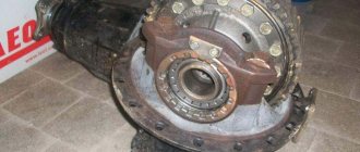
To diagnose the condition of the coupling, you need to gain access to the unit. To do this, disconnect the engine from the transmission and roll out the tractor. Then an initial inspection of the unit is performed. Then unscrew the six nuts securing the basket to the flywheel and dismantle the assembly for a full inspection.
Release bearing condition
The bearing is replaced: the contact surface is worn out, it is noisy when rotating and has play in the races, the bearing is jammed.
Practitioners recommend that, in addition to the original bearing of the MTZ 80 tractor, you can install a KamAZ 5320 release bearing, which has proven itself in the operation of the tractor clutch mechanism.
When worn out at the contact areas of the bearing and fork drive, the parts can be restored by welding metal, followed by processing to the appropriate size.
Condition and degree of deterioration of the working surfaces of the feet and their integrity
When the working surfaces of the legs exceed 2.5 mm, they are replaced or welded on with subsequent processing.
When installing new paws, you need to pay attention to the contact plane of the levers with the release bearing. Often, castings of levers have non-identical contours and a contact surface; when applied to a bearing, they protrude beyond the working surface, capturing the part holder
In this case, the protruding part is ground off. When replacing paws, you also need to pay attention to the degree of metal hardness. One of the reasons for the rapid erasure of the feet after repair is the mismatch of the material used or the lack of hardening of the working surfaces of the part.
Friction disc condition
If cracks, uneven wear, lifting of the linings, wear of the hub splines and play, loss of damper springs, as well as sufficient wear of the linings are detected, in all cases the disc is replaced.
Condition of the working plane of the basket pressure plate and the mounting holes for the paws
In case of uneven wear of the pressure plate, leveling by milling and grinding is allowed, taking into account the tolerance of the disk thickness of at least 21 mm. If the mounting holes for the release levers are broken into an ellipse, or if cracks are detected, the disc is replaced with a new one.
Flywheel contact plane condition
If acceptable ellipse of the flywheel surface is determined, alignment is carried out by milling and grinding. If the surface is worn too much, it must be replaced.
After defect detection of parts has been carried out, based on the condition, a decision is made: to carry out routine repairs of the unit with the replacement of worn parts or to replace the assembled unit.
How to properly adjust the clutch of the MTZ-80 tractor
Like any technical unit or unit, the clutch of the MTZ-80 tractor requires preventive maintenance, periodic checking and adjustment if necessary. If you know the clutch design (and it is actually extremely simple), it will not be difficult for even an inexperienced tractor operator to perform all the required actions.
Detailed diagram of the clutch device for Belarusian tractors of the MTZ brand
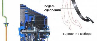
Clutch and brake control mechanism:
1 – clutch rod; 2 – brake rod; 3 – shift fork shaft lever; 4 – bracket; 5 – bolt; 6 – thrust bolt; 7 – clutch pedal; 8 – spring of the servo device.
Clutch replacement MTZ Belarus - prices for work
Adjusting and replacing the clutch at MTZ Belarus
| Name of works | price, rub. |
| Replacement | from 25 000 |
| All work with the engine removed | 2 500 |
| Works | price, rub. |
| Adjustment | 1 500 |
| Remove/install the flywheel with the engine removed | 1 500 |
| Replace the flywheel crown with the engine removed | 1 200 |
We carry out replacement of any components and complete repairs of MTZ 82,80,320,920,1221 and other models. We have the ability to carry out all work on site. Mobile teams are staffed with experienced specialists and all the necessary equipment.
MTZ tractor clutch
The clutch disc is a very important part of the transmission of any modern tractor. For example, if the spring pressure in the disk weakens, over time the clutch will begin to slip.
Malfunctions of the Belarus clutch mechanism:
The main reason for clutch failure is disc wear. When using equipment for a long time with a worn clutch, the disc begins to warp. The friction linings of parts wear out over time, and rivet heads may weaken. This may cause the pressure plate to become overheated.
Despite this, with the necessary care, both the flywheel and the disk can last a long time. An important point is to recognize the first signs of a possible breakdown and remove them. Clutch adjustment for Belarus MTZ 82, 80, 320, 311 should be carried out according to the parameters of a specific model. If there is an oil leak through the shaft seal of a vehicle engine or gearbox, you must use the services of a service center. In addition, it is very difficult to eliminate oil leakage from internal oil seals on your own - this procedure requires rolling out the tractor.
How to find out if the clutch disc has failed? The pressure plate may become warped when the vehicle’s clutch is engaged, causing the vehicle’s clutch to “lead.” In addition, the thickness of the pressure plate decreases over time. In this case, employees advise changing the friction lining (in modern conditions, I usually change the entire disk assembly).
You can purchase new discs from us complete with a clutch basket and release bearing (layer). Since repair work on this mechanism is very labor-intensive and time-consuming, it is better to replace all failed parts (even with partial wear) so as not to overpay for reassembly and disassembly.
You can tell that the discs are starting to fail by the difficulty of engaging the gears. For this reason, you need to be attentive to your own technique. In particular, you need to check the disks and their performance through special hatches - visually. Remember that all mechanisms must be in good condition.
Stages of work:
- Diagnosis of the clutch is carried out first. The technician carefully diagnoses all parts and identifies all faults.
- Rolling out the MTZ tractor consists of two stages: It is necessary to select a place to perform the work. We choose it as even as possible so that there is no slope. Choose hard ground.
- We decide what technique to use for rolling. If you have a box with a beam crane, hoist, or other lifting mechanism, then you need to use them. If a lifting mechanism is not present, then there are two methods for rolling out the tractor to change the clutch.
If you don't help, you won't go
This does not apply to bribes, but it is necessary to know the use of the necessary lubricants.
In addition, it is important to comply with the regulations of the work carried out and the deadlines for their completion. The MTZ tractor is designed to use the following fuels and lubricants: Clutch adjustment should be carried out (the clutch is at least inspected) every 60, 240 operating hours, lubricating the release bearing with the above means. On some more modern tractor models, the time limit has been almost doubled, which does not cancel a similar action plan.
Lubrication is carried out through the neck of the oiler, located on the outlet housing or on the clutch housing itself, connected by a flexible hose to the bearing. When adjusting the clutch, check the free play of the pedal (usually 40 to 45 mm) from the release bearing to the release levers.
MTZ spare parts catalog
The MTZ online spare parts store “Agrosila74” offers a large selection of spare parts for the MTZ tractor. The MTZ 82 spare parts catalog is a large assortment of spare parts in stock and on order with delivery in Chelyabinsk and throughout Russia. We always have in stock in our warehouse:
- Engines;
- Engine parts;
- Gearbox;
- Spare parts for gearboxes;
- Clutches;
- Mostov;
- Starters;
- Generators.
The most complete selection is available in the “Spare parts MTZ-80/82, D-243” section on our website.
Buy spare parts MTZ 80/82
To prevent tractor repairs from resulting in unnecessary costs, you need to buy MTZ 80/82 spare parts from a trusted supplier. Only original and high-quality spare parts for the MTZ tractor, this is a guarantee of stable operation and durability. Choosing a good online store for tractor spare parts is also not an easy task.
A good online store has a catalog of MTZ spare parts with a rich selection, provides comprehensive information about the product, gives the necessary advice, and also delivers at a convenient time and place. The MTZ spare parts online store “Agrosila74” allows you to buy MTZ 80/82 spare parts profitably for a number of reasons.
We offer to buy MTZ 82 spare parts, the price of which will be the most favorable. Our specialists will provide you with the necessary assistance in choosing spare parts and advise on all questions of interest. If the required spare part is not available, you can order MTZ 82 spare parts at a favorable price. We deliver in Chelyabinsk and throughout Russia.
We have extensive experience in the market, work directly with manufacturers and sell only original spare parts for the MTZ 80/82 tractor. Therefore, it is profitable to buy MTZ 80/82 spare parts from us.
Step-by-step procedure for checking and adjusting the clutch
- It is necessary to disconnect the brake rod from the lever by first removing the pin.
- In order for the bracket to move freely, it is necessary to screw the stop bolt into it, releasing the pedal and loosening the bolts from the spring pressure.
- Free movement of the pedal is adjusted by changing the length of the rod. On the pillow from 40 to 45 mm.
- By rotating counterclockwise, you need to move the bracket until it stops against the bolt, and then tighten all the mounting bolts of the bracket.
- Then depress the clutch pedal by unscrewing the stop bolt. In this case, the pedal itself should return to its place under the action of the spring. If the return does not occur, you must repeat all previous steps.
- To adjust the length of the brake rod, rotate the lever counterclockwise until rotation stops. Then, connecting the lever to the rod, set the required length. After this, disconnect the rod again and shorten its length by 7 mm. Finally, reconnect the lever to the rod by inserting the pin and securing it with the locknuts.
The entire assembly after adjustment is performed strictly in the reverse order. You can read all the numerical parameters of the quantities required when adjusting the clutch on Belarusian MTZ tractors in the table:
How to adjust the clutch
Let's consider what this mechanism consists of. The clutch device includes friction discs pressed tightly against one another. These discs are located in the clutch. The transmission is engaged when the driving disc slips against the driven disc. They are connected to each other by a splined unit and a gearbox. When the pedal is released, the circuit turns on, and then the discs are pressed tightly together, and are separated when the pedal is pressed. At this moment, a gap appears between the disks.
The MTZ-82 and 80 tractors from the Minsk plant have a single-disc, single-thread mechanism, which includes:
- flywheel;
- pressure and support disks;
- 12 pressure springs located between the discs.
Farmers ask how to install the clutch of the MTZ 80 tractor. Installation is carried out at the factory, but if repairs need to be made, you can do it yourself. The tractor is equipped with parts that can wear out during long-term use of the equipment. That is why the MTZ clutch is adjusted and the paw or disc is replaced.
Let's look at how the MTZ-82 clutch paws are adjusted:
- First you need to unfasten the rod from the lever by extending your finger.
- Unscrew the MTZ-82 clutch adjustment bolt and set the pedal to its original position.
- After this, you need to unscrew the lever counterclockwise until the bearing stops, which is fixed into the release levers.
- Next, I adjust the traction fork, which will allow me to connect the hole of the lever and the fork.
- Reduce the thrust by 5 turns of the fork, then connect it to the lever using your finger.
- Check the health of the system.
The next stage of repair of the MTZ-82 clutch involves moving the pedal to the initial position. To do this, you need to move the pedal to the full stroke length. If sagging is observed, you need to unscrew the bolts by turning the bracket clockwise.
If replacing the MTZ-82 clutch is not carried out by adjusting the rod length, then the position of the levers must be changed. When the adjustment is completed, tighten the locknut and secure the pin.
After adjusting the clutch, you need to start adjusting the release levers. Here you will need a frame that is made according to the inner diameter of the hub. It has an end surface designed to support the levers. They must be brought back to normal using nuts that will allow the levers to be brought all the way to the end, and lock washers installed.
Check and possible malfunctions
Like any moving mechanical unit, the clutch is subjected to strong and serious workload during operation, which sooner or later leads to failures and breakdowns.
It doesn’t take much intelligence to determine that the clutch system of a Belarusian tractor is functioning properly. Remember two main signs of its high-quality work:
- When the clutch is operating, the discs do not slip relative to each other, sending regular force from the diesel engine;
- When you depress the pedal, you should immediately feel that the clutch is completely disengaged.
It is necessary to check and inspect the clutch system every third maintenance (technical inspection), paying special attention to the transmission of torque from the diesel engine. That is, carefully inspect the clutch every 960 operating hours of the tractor.
The check is carried out simply: the tractor is driven onto a flat, straight surface, where it is started in any gear, setting the crankshaft speed to an average level, and then the machine is stopped and, if the diesel engine stops working after stopping, then everything is fine with the clutch, and if the engine only slows down the rotation of the crankshaft, then the problem is that the clutch slips.
The release bearing hummed. To smear or to change? What's better
A customer recently came in with a noisy release bearing and asked to lubricate it. He says he read it on the Internet and was advised to just stuff it with lubricants to fix the problem. I advised you to come with a new bearing, or better yet, a complete clutch kit.
Who do you think is right? – Write in the comments. And I’ll tell you why I abandoned the idea of lubrication.
The noise of the release lever is the first sign of its replacement. There is no doubt that if it makes noise, it means it is running dry. And, it would seem logical, why not lubricate it then... However, as in the case of a CV joint, lubricant is already like a “dead poultice.”
Why? Along with the noise, shells have already appeared on the balls! Yes, you can stuff lubricants in there. What's the point? The sinks aren't going anywhere. For some time, with lubrication, it may begin to work more quietly, but...
Due to defects, the temperature inside will rise, the lubricant will be squeezed out, and in a week it will make noise again!
Removing the release bearing itself is far from an easy and cheap task. In any case, you will have to remove the gearbox. And dismantling the clutch for the sake of lubrication or replacing one bearing is a bad thing.
You can decide to change the bearing itself, but you should take a high-quality one. But if the bearing is noisy, then most likely the clutch will soon have its time. Then it goes back to repairs...
What do you think about partial repairs there and who advises people on this? Write in the comments, click like if you support me and share with others on social networks!
Source
Troubleshooting
Wear and failure of clutch parts can be determined by the appearance of:
- difficulties when changing gears;
- extraneous noises and knocks;
- clutch slipping.
If a strong noise or whistle occurs when you press the clutch pedal, most likely the release thrust bearing has failed. As for slippage, its main cause is oil getting on the discs due to leaks through the gearbox or crankshaft shaft seals.
During operation of the tractor, cracks and rainbow colors may appear on the surface of the pressure plate. This is due to worn linings and bent clutch discs.
When does a mechanism need to be replaced?
Let's consider when there is a need to replace this mechanism. Replacement and repair of the MTZ-82 clutch is carried out in the following cases:
- The device does not allow you to obtain full torque.
- The pedal moves partially or the radius of its movement increases several times.
- The driven disc linings, lift brackets or cuffs are worn.
- Doesn't turn off completely.
- Oil gets onto a dry disc.
- The drive shaft bearing cap has been squeezed out.
The MTZ-80 clutch basket is repaired and adjusted in the same way. This wheeled tractor model, like the 1221 and 320, has the same reasons for clutch wear.
Repair
If, when operating the MTZ-82 tractor, you can hear gears grinding while shifting gears, it means:
- clutch discs are worn out;
- The control mechanism is not adjusted correctly.
After troubleshooting and adjusting the clutch, the grinding noise should disappear. If this does not happen, then you need to start adjusting the mechanism that tensions the brake spring. You can check the correct setting of this mechanism by the length of the compressed spring - it should be 31-32 millimeters.
Is the problem still there? This means that it is necessary to remove the cabin floor, as well as the cover of the reduction gearbox and the hatch of the coupling basket. Having done this, measure the thickness of the disc linings - it should be at least 1.5 mm. Otherwise, the brake disc should be replaced. To do this, disconnect the clutch housing from the gearbox, roll out the tractor island and remove the cover of the reduction gearbox. After this, all that remains is to dismantle the clutch shaft using technological bolts, and then replace the brake disc.
Cost of tractor repair services
| VMTZ tractors (T-25, T30-69, Agromash 30TK, etc.), Chinese tractors (FOTON, DONGFENG, JINMA, etc.) | |
| Engine dismantling and installation | 8 000 |
| Clutch replacement | 12 000 |
| Brake repair | 13 000 |
| Transmission repair | 23 000 |
| Tractors MTZ-82 | |
| Dismantling and installation of the engine (starter version) | 9 000 |
| Dismantling and installation of the engine (starter) | 10 500 |
| Repair (replacement) of clutch (starter) | 23 000 |
| Repair (replacement) of clutch (starter) DZ-133 | 23 000 |
| Repair (replacement) of clutch (starter) MK | 23 000 |
| Re-equipment of the gearbox for GCU | 18 000 |
| checkpoint | 18 400 |
| Repair of the final drive of the axle (replacement of the axle shaft) | 18 000 |
| Brake repair | 9 500 |
| YuMZ tractors | |
| Dismantling and installation of the engine (starter) | 10 000 |
| Dismantling and installation of the engine (starter) | 10 500 |
| Repair (replacement) of clutch (starter) | 23 000 |
| Gearbox (repair with disassembly and assembly work) | 35 000 |
| Tractors LTZ-55(60), T-40 | |
| Dismantling and installation of the engine (starter) | 8 800 |
| Dismantling and installation of the engine (starter) | 9 800 |
| Repair (replacement) of clutch D-144 | 20 000 |
| Repair (replacement) of clutch D-65 (starter) | 20 000 |
| Repair (replacement) of clutch D-65 (launcher) | 20 000 |
| Gearbox (repair with dismantling and installation) D-144 | 28 000 |
| Gearbox (repair with dismantling and installation) D-65 (starter) | 35 000 |
| Gearbox (repair with dismantling and installation) D-65 (launcher) | 35 000 |
How to replace a clutch
To assemble a clutch from old parts or install new ones, you need to use a special device sold at the appropriate retail outlets. Compress the pressure plate springs and insert the process bolts to secure them. Then mount the process shaft into the flywheel bearing race (inner). It is needed for the correct mutual installation of the driven disk hubs.
Clutch adjustment
Rotating the rod allows you to adjust the free play of the clutch pedal. The pedal lever in the released position should rest against the floor of the tractor cab. If this is not the case, you need to adjust the system by gradually unscrewing the thrust bolt from the bracket. It happens that this adjustment does not lead to the desired results. In this case, you need to loosen the bolt securing the bracket, and then turn the bracket clockwise - towards the spring.
If the clutch release mechanism is adjusted correctly, the gap between the protrusions of the levers should be 2.5-3.5 mm.
Source
Repair of clutch and reduction gear MTZ
08.04.2018
Tractor clutch MTZ-80
Slipping of the clutch or incomplete disengagement of gears leads to increased wear and damage to parts of the clutch, gearbox, rear axle and front axle of the MTZ-80 tractor.
The technical condition of the clutch can be determined by a number of signs that characterize a particular malfunction.
The appearance of abnormal noise and knocking, difficult gear shifting, clutch slipping, especially with increasing traction force, which cannot be eliminated by adjusting the clutch drive, indicate wear or destruction of clutch parts.
Increased noise or whistling when pressing the clutch pedal indicates destruction of the release thrust bearing.
If the MTZ-80 clutch drive is incorrectly adjusted, which is characterized by a lack of clearance between the thrust bearing and the pressure levers, the bearing constantly rotates. This leads to overheating of the bearing, leakage of lubricant and, ultimately, to destruction of the bearing. In most cases, jamming of a faulty bearing is accompanied by burning of the ends of the pressure levers.
Incorrect adjustment of the drive, weakening the force of the springs of the pressure plate (basket) can lead to slipping of the clutch, a decrease in the traction force of the tractor, and a decrease in the speed of rotation of the power take-off shaft.
During operation of the tractor, the driven clutch discs warp, the linings wear out, and the rivet heads cause significant annular marks on the surface of the basket. Due to increased local heating, tarnish and cracks may appear on the working surface of the pressure plate.
Clutch slipping may be a result of oil getting on the surfaces of the discs due to leaks through the seals of the diesel crankshaft or gearbox shafts.
If the driven disks are warped or the release levers are incorrectly adjusted (when the ends of the levers are located at different heights), it is difficult to engage the gears. In this case, the pressure plate becomes skewed when the clutch is released: the edges of the driven disk are pinched between the pressure disk and the flywheel. As a result, the clutch “leads”.
If the thickness of the driven disk is less than the permissible size, replace either the friction linings with new ones or the disk assembly. Difficulty shifting gears can be caused by jamming of the hub splines on the clutch shaft splines due to their stepwise wear.
When disassembling the clutch, simultaneously with eliminating the identified malfunction, a technical examination of the parts is carried out in order to replace them with new or repaired ones.
Before removing the clutch, special technological bolts are screwed into the flywheel, providing preliminary compression of the pressure springs (Fig. 2.5.1), and the support disk mounting bolts are unscrewed, and then the technological bolts.
Before disassembling the clutch, marks are applied to the housing and pressure plates, trying to ensure the correct relative position of the parts during assembly and maintain the original balancing of the clutch. The clutch is disassembled using a special device (Fig. 2.5.2).
Rice. 2.5.1. Removing the MTZ-80 clutch
1 — clutch; 2 - technological bolt; 3 — support disk mounting bolt
Rice. 2.5.2. Disassembling the support plate and clutch basket
1 - two-jaw puller; 2 — support disk; 3 - technological bolt
Acceptable values of controlled data for the MTZ-80 clutch of the D-240 diesel engine, mm
Driven disk thickness - 8.0 Driven disk warpage - 0.6 Pressure disk thickness - 21.0 Shaft spline thickness - 3.5 Release lever cam height - 10.9
After replacing the friction linings, the recession of the rivet heads should be at least 2.0 mm. The pads should fit snugly to the disc; Leaks of up to 0.1 mm are allowed, as well as radial cracks of the linings near the rivets without them extending to the edge or into another hole for the rivet.
If the thickness of the driven disk is not less than the permissible value, but the heads of the rivets are buried below the plane of the lining by 0.1 mm or less, then both friction linings are replaced.
Inspect the condition of the MTZ-80 basket. On its supporting plane, ring marks with a depth of more than 0.2 mm, burn marks and cracking patterns of more than 40% of the entire surface are not allowed. The working surface of the pressure plate is corrected by grinding or grinding until signs of wear are removed and thoroughly cleaned with fine sandpaper.
The clutch is assembled using a device (see Fig. 2.5.2). The springs of the pressure plate are compressed and the technological bolts are screwed in to fix this position.
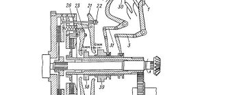
A process shaft (Fig. 2.5.3) is installed in the inner race of the flywheel bearing, which is necessary for the correct mutual installation of the splined hubs of the driven disks and ensuring their alignment with the flywheel. Unscrew the technological bolts from the casing and remove the technological spline shaft.
Rice. 2.5.4. Clutch adjustment and braking MTZ-80
1 - thrust bearing; 2 — release lever; 3 — pedal lever; 4, 8 — brackets; 5 — brake rod; 6 - fork; 7 - thrust bolt; 9 - traction; 10 — bracket fastening bolt
Rice. 2.5.3. Centering the driven disk
1 - technological shaft; 2 - support disk
Rice. 2.5.5. Adjusting the clutch release levers
1 — release lever; 2 - technological shaft
The free travel of the clutch pedal (pull position) (Fig. 2.5.4) is adjusted by rotating rod 9. When released, pedal lever 3 should rest against the floor of the cabin. If it does not rest, gradually unscrew the thrust bolt 7 from bracket 8. When such adjustment is not enough, loosen the bracket mounting bolt 10 and turn the bracket towards the spring (clockwise).
If the clutch release mechanism is adjusted correctly and the size of 12 ± 0.5 mm is observed, the gap between the protrusions of the levers 2 and the thrust bearing 1 should be 3 ± 0.5 mm (adjustment of the clutch release levers is shown in Fig. 2.5.5).
Adjustment of the MTZ-80 brake adjustment is carried out in two stages (see Fig. 2.5.4). First stage: disconnect rod 5 from bracket 4, turn bracket 4 to the right (counterclockwise) until it stops; by rotating the fork 6, increase the length of the rod 5 until the fork 6 and bracket 4 are freely connected.
Second stage: rotate the fork 6 until the total length of the rod 5 decreases by 7 mm; in this position, connect the fork to the bracket. After adjustment, the fork is secured with a lock nut.
During operation of the tractor, other failures and malfunctions of the gear shift mechanisms may occur. To eliminate them, remove the clutch housing and disassemble it in the sequence shown in Fig. 2.5.11—2.5.28.
Rice. 2.5.11. Removing the clutch shaft bearing retaining ring
1 - retaining ring; 2 — clutch shaft; 3 - support cover
Rice. 2.5.13. Removing the hydraulic pump drive intermediate gear
1 - intermediate gear; 2 - locking screw
Rice. 2.5.14. Pressing out the bearing from the hydraulic pump drive intermediate gear
1 - bearing; 2 — instruction; 3 - gear
Rice. 2.5.15. Pressing the brake lifting bracket
1 — brake lifting bracket; 2 - technological bolt; 3 - bolt
Rice. 2.5.16. Pressing out the bearing from the brake release bracket
1 - bearing; 2 — bracket; 3 - collet; 4 - inertial puller
Rice. 2.5.18. Pressing out the PTO drive drive shaft bearing from the lift-off bracket
1 - bearing; 2 — layering bracket; 3 - puller
Rice. 2.5.19. Removing the bottom cover assembly with the PTO drive gear shift fork
1 - cover; 2 - bolt
Rice. 2.5.20. Removing the driven shaft cover of the MTZ-80 PTO drive
1 - cover; 2 - bolt
Rice. 2.5.22. Pressing out the driven shaft of the PTO drive, removing gears of the 1st and 2nd stages, removing the coupling
1 — instruction; 2 — clutch housing
Rice. 2.5.23. Pressing the bearing out of the clutch housing
1 — bearing; 2 — clutch housing; 3 - inertial puller
Rice. 2.5.27. Pressing out the needle bearing of the driven shaft of the PTO drive
1 — needle bearing; 2 — clutch housing; 3 - inertial puller
Rice. 2.5.28. Pressing out the bearing from the driven gear of the second stage of the PTO drive
1 - bearing; 2 — gear II stage; 3 - collet; 4 - inertial puller
Reduction gearbox MTZ-80
Most malfunctions of the switching mechanisms of the MTZ-80 reduction gearbox are associated with the occurrence of the following main defects: spontaneous shutdown and difficult gear shifting, the appearance of noise and knocking.
The gears switch off spontaneously when the teeth of the gears and gear couplings are worn and chipped, the clamps and the recesses for them on the rollers of the gear shift mechanism are worn out, the springs of the clamps lose elasticity, the friction surfaces of the shift forks, the rockers, the annular grooves of the sliding gears and gear clutches are worn out.
Stiff shifting of gears and their inclusion with a grinding noise occur (along with incomplete disengagement of the clutch) when the brake adjustment is violated or the locking mechanism does not work properly.
Increased noise and knocking in the gearbox occurs due to wear of the shaft bearings, bearing seats in the housing, misalignment of the shafts, insufficient oil in the gearbox housing, cracks and broken parts.
The noted malfunctions arise not only due to fatigue wear of the mechanisms, but also due to improper operation and non-compliance with technical conditions during repairs.
Thus, increased wear of bearings and gear teeth in thickness can be caused by the presence of abrasive particles in the oil poured into the gearbox housing, or the entry of such particles into the lubricant through leaks.
Chips and destruction of gear teeth on the engagement side appear due to inaccurate adjustment of the clutch, incorrect gear shifting, and improper adjustment of the clutch shaft brake.
Fatigue chipping of gear teeth is significantly accelerated by incorrect meshing of gear pairs, their incomplete engagement, or inaccurate adjustment of the meshing of bevel pairs. During operation, a number of malfunctions can be eliminated directly on the tractor.
If during operation of the tractor you can hear the grinding of gears that occurs when changing gears, this indicates improper adjustment of the clutch control mechanism and wear of its discs, wear of the friction discs and brake, wear of the surfaces at the junction of the fork and the brake release pin (Fig. 2.5. 6).
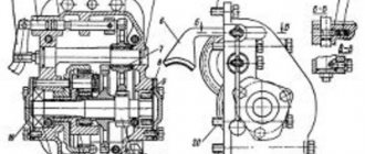
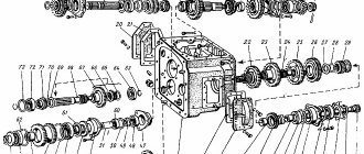
Rice. 2.5.6. Clutch and reduction gear MTZ-80
a - general view; b - relative position of parts; 1 - damper; 2 — driven disk; 3 — pressure disk; 4 — support disk; 5 — release lever; 6 — thrust bearing; 7 - layering; 8 — layering bracket; 9, 15, 16, 26, 39, 40, 54, 58, 62 - rings; 10 - cuff; 11 — oil deflector washer; 12, 14, 18, 27, 29, 38, 56, 61 - bearings; 13 - thrust bushing; 17 — intermediate gear; 19 — gear axis; 20 — fixing screw; 21 — clutch housing; 22, 50, 63 — gaskets; 23, 24 — covers; 25 — PTO drive shaft; 28 — thrust washer; 30 — brake lifting bracket; 31 — power plug; 32 — brake release; 33 — brake disc with lining; 34 — gear coupling; 35 — clutch shaft; 36 - gear; 37 — support cover; 41, 44 — levers; 42 — clutch fork shaft; 43 — brake rod; 45 — power fork shaft; 46 — clutch cover; 47 — PTO gear shift fork; 48 — PTO gear shift shaft; 49 — bottom cover; 51 — needle bearing; 52 — PTO drive shaft; 53 - coupling; 55 — PTO drive gear (II stage); 57, 60 — spacer washers; 59 — PTO drive gear (1st stage); 64 — bearing cover
Large free play of the gear shift lever of the MTZ-80 reduction gearbox indicates wear of the shift fork and gear coupling groove.
To check wear, disconnect the fork, insert it into the groove of the gear coupling and measure the gap. If the gap exceeds 3 mm, then the coupling and fork are replaced. To replace the gear coupling, roll out the core and disconnect the clutch housing from the gearbox.
Rice. 2.5.7. Removing the control mechanism for the reduction gearbox and gear coupling MTZ-80
1 — control mechanism; 2 - clutch shaft
Rice. 2.5.8. Pressing out the clutch shaft and removing the brake drive disc
1 - technological bolt; 2 - clutch shaft
Rice. 2.5.9. Removing the thrust bearing, offset, shift forks and clutch fork shaft
1 - layering; 2 - fork; 3 — clutch fork shaft
Rice. 2.5.10. Removing the brake lift
1 — brake release; 2 — power plug; 3 - power fork shaft
Source
Clutch housing. Disks. Layering. Tractor MTZ 80
Clutch housing. PTO drive. Tractor MTZ 80
Clutch housing. Reduction gear. Tractor MTZ 80
Clutch basket: replacement, adjustment, repair features
Tags: clutch disc, Clutch housing, mechanical engineering, lift assembly, repair, clutch
Author: Administrator
How to make adjustments on MTZ-320
Let's look at how the clutch is adjusted on the MTZ-320 and how to correctly install the clutch disc. Like tractors such as MTZ-80, 82 and 82-1, the MTZ-320 has a dry single-disc friction clutch, which is of the permanently closed type.
The clutch is fixed to the flywheel with 6 bolts placed on three pins. The torque from the pressure disk and the flywheel of the motor passes to the driven disk, and then to the shaft. Between the release discs there are 9 pairs of springs.
The pedal can move freely in the basket, but the limit is 40 mm. If this parameter is larger, it will be difficult to shift the gearbox and problems will arise with the operation of the mechanism.
If the pedal travel is insufficient, slipping may well occur, which threatens wear on the discs.
You can cope with this situation by installing the MTZ-320 clutch. This is done according to the following scheme:
- You need to unfasten the rod from the lever and pull out the finger.
- Rotate the lever counterclockwise until the bearing stops in the lever. Then you need to turn the traction fork, connect the holes on the lever and the fork.
- You need to turn the fork a few turns and try to connect it to the lever, for which you need to use your finger.
- At the very end of the contract, the finger is secured.
- After this, it is necessary to check the serviceability of all components and fasteners that are included in this system of the MTZ mini-tractor.
When adjusting the MTZ-1221 clutch, adjust all the devices that together make up the MTZ clutch. Unlike the models of mechanisms installed on MTZ-80, 82 and 320, clutch adjustment on 1221 involves working with a different type of system.