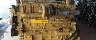
How to stop an excavator?
Photo source: exkavator.ru You can determine the causes of a hydraulic system malfunction using the logical method of finding them
If a malfunction has led to the loss of machine functions, and/or has a negative impact on the safety of its operation, or harms the environment (for example, a break in a high-pressure hose), then the machine should be stopped immediately.
To ensure safety when stopping the machine, the following measures must be taken:
- lower all suspended working parts of the machine or fix them mechanically;
- relieve pressure in the entire hydraulic system;
- discharge all hydraulic accumulators;
- relieve pressure from pressure transducers;
- turn off the electrical control system;
- turn off the electrical power.
It should be taken into account that the working fluids used in hydraulic drives are low-compressible compared to gas and expand slightly when the pressure decreases. However, in those places in the hydraulic system where compressed gas may be present (due to insufficient deaeration or when a hydraulic accumulator is connected), the pressure should be reduced very carefully.
Unloading
Unloading is carried out by turning the “jaw” while simultaneously lifting the boom. After unloading, turning the excavator towards the face, the driver lowers the bucket to the starting position for digging. In this case, pressure from the pumps is supplied to the rod cavities of the hydraulic cylinders of the bucket and arm. The boom lowers without pumping. The pressure in the piston cavities of the drives decreases when each of the three elements of the digging mechanism is lowered.
According to the processing of oscillograms of the digging processes of the EG-12A and EG-20 excavators, during the development of rock faces of the Sh - 1U category according to ENV, graphs of changes in the average and maximum pressures in the lines of the piston cavities of the hydraulic cylinders of the handle and bucket were constructed.
How to approach hydraulic system diagnostics?
Hydraulic system malfunctions can be divided into two types:
- malfunctions that do not affect (of course, up to a certain time) the functioning of the machine - a functional problem in the hydraulic system (for example, an increase in leakage, temperature, etc.);
- malfunctions affecting the functioning of the machine - a functional problem in the machine (for example, decreased productivity).
The search for different types of faults is performed using different algorithms.
There may be cases where the same malfunction (for example, a pump) can lead to a functional problem in both the machine (reducing performance) and the hydraulic system (increasing noise levels).
Read
We study special vehicles from the inside. Hydraulic distributors guides
Experience has shown that it is preferable to start troubleshooting with the main problems and work through test procedures, taking into account signs such as increased temperature, noise, leaks, etc., as “guiding threads”. Common sense is crucial, as certain symptoms can directly point to a problem area. The stream of oil flowing from the hydraulic cylinder seal indicates where the problem area is.
Photo source: exkavator.ru The same malfunction can lead to a malfunction in both the machine and the hydraulic system
However, some symptoms are not so obvious. If a flow leak occurs in any node during the transition from high pressure to low, then local heat release occurs in it, which is not always immediately detectable.
No matter where you start your search, certain questions need to be answered before you take action. If a problem is reported, it is necessary to gather as much factual information as possible. Perhaps this problem has already occurred and is recorded in the operational documents. In this case, you can save a lot of time. It should be checked whether any maintenance or adjustment work was carried out on the system shortly before the malfunction occurred. It is necessary to determine the exact nature of the malfunction: did it arise suddenly or develop gradually over a long period of time, and the operation of which parts of the machine it affects.
Photo source: exkavator.ruIf there is a flow leak in any node, then local heat release occurs in it
Characteristics of hydraulic excavators
- bucket capacity - up to 50.0 m³
- digging depth below the installation level - up to 5 m (straight shovel)
- length of the planned site - up to 14 m
- scooping height - up to 22 m
- scooping radius - up to 22 m
- unloading height - up to 17 m
- unloading radius - up to 20 m
- tail radius - up to 10 m
- bucket penetration force - up to 4000 kN
- breaking force on teeth - up to 1600 kN
- pump drive motor power - up to 2700 kW
- working pressure in the hydraulic system - up to 32 MPa
- number of main pumps - up to 8
- pump flow - up to 8000 l/min
- electric motor power: turning - up to 800 kW, travel - up to 400 kW
- travel speed - up to 0.8 km/h
- ground clearance of the undercarriage - up to 1.05 m
- ground pressure - up to 0.32 MPa
- operating cycle duration: up to 37 s
- operating weight - up to 900 t
How to determine the simplest faults in the hydraulic system?
There are two ways to identify faults:
- using the senses;
- using instruments and instruments.
The simplest malfunctions of the hydraulic system can be determined using the senses - seeing, feeling, hearing - and very quickly. In practice, many problems are solved in this way, without the use of any tools.
| Leakage of working fluid | At the junctions of elements | — Weak tightening of threaded connections — Destruction of sealing elements (cuffs, rings) |
| Foaming of working fluid | In the oil tank | — Air leak in the suction hydraulic line — Low level of working fluid in the tank |
| Insufficient speed of operations | Working parts of the machine | — Large leaks of working fluid — Insufficient pump flow |
| Insufficient effort when performing operations | Working parts of the machine | — Large leaks of working fluid in the system — Incorrect setting of the safety valve |
| Noise during pump operation | Pump | — Cavitation in the suction pipeline — Misalignment of the pump shafts and drive unit — Wear of drive gears and couplings |
| Noise and knocking when valves operate | Valve | — Valve clogged — Spring broken — Valve assembly out of adjustment |
| Heating the working fluid to a temperature of more than 60 °C | On pipelines | — Low level of working fluid in the tank — Clogged filters — Clogged breather |
| Pump heating | On the pump housing and adjacent components | — Low feed and, as a consequence, insufficient speed of work operations |
| Heating of hydraulic cylinders and hydraulic motors | On the body of the hydraulic cylinder, hydraulic motor and adjacent pipelines at a distance of 10-20 cm | — The hydraulic cylinder is faulty (wear of the seals, damage to the piston) — The hydraulic motor is faulty (wear of the pistons and distributor, failure of the bearings) |
| Heating of hydraulic valves | On the hydraulic distributor housing and adjacent hydraulic fluid drainage pipelines | — The hydraulic distributor is faulty (spool wear, valve malfunction) |
If the fault cannot be identified using the senses, then it is necessary to use instruments: pressure gauges, flow meters, etc.
Features of pressure changes in the hydraulic cylinders of a mining hydraulic excavator
The processes of changing pressure in the hydraulic cylinders of the digging mechanism of an excavator, as a cyclic machine, are mainly of a two-component nature. The overall process consists of a low-frequency continuous component and a periodically occurring high-frequency component. Low-frequency changes in pressure are caused by the periodically repeating nature of the movement of the executive bodies (digging, lifting a loaded bucket, unloading, lowering the bucket into the face) during the excavation cycle. High-frequency oscillations occur during the digging process, when the change in pressure in the hydraulic system is determined by the characteristics of the face, as well as during other operations (starting and braking of digging mechanism elements).
High-frequency components of pressure change processes
High-frequency components of pressure during digging have the greatest amplitude during active penetration of the bucket. The frequency of pressure oscillations is 1.2.3 Hz, the amplitude in bucket hydraulic cylinders is 1.8. 4.1 MPa, in hydraulic handle cylinders - 2.3. 5.3 MPa. An idea of the process of changing pressures in the hydraulic system during an excavation cycle can be compiled from data from statistical processing of oscillograms obtained during operation of the EG-20 excavator.
Low frequency components of pressure
Low-frequency components of the processes of pressure changes in the piston cavities of the hydraulic cylinders of the boom, arm and bucket are shown with irregular lines, the dotted line shows the envelope of maximum pressures. The broken lines indicate the coordinates of the position of the arm and bucket relative to the extreme positions. Moreover, if the increase in pressure from the zero lines occurs from top to bottom, then the increase in coordinates from the extreme lower positions occurs from bottom to top. Horizontal sections of coordinates indicate the immobility of the element (hydraulic cylinders are locked).
The highest absolute value active and reactive pressures in the hydraulic system during the entire excavation cycle occur during the digging process.
Typically, digging is carried out by simultaneously turning the bucket and extending the handle. The active pressures in the hydraulic cylinders of the bucket and arm increase as the bucket is inserted. The boom gradually lowers under the influence of weight. Maximum pressures develop over time in the second half of digging. Towards the end of digging, the pressure decreases, as the active penetration of the bucket ends and its removal from the face begins. An increase in pressure in the bucket lines occurs as a result of stopping the bucket in the extreme position, when the operator, without feeling this, continues to hold the control handle to turn the bucket.
This style of control is not inherent in all drivers and depends on skills and experience. The last two seconds of digging are taken by removing the bucket from the face by raising the boom to make a turn for unloading.
During the digging process, the pressures developed by the pumps in the cylinders of the handle and bucket are cut off, since the rod and piston cavities are locked, and when the bucket is removed from the face, the excess pressures of the piston cavities are balanced by an increase in pressure in the rod cavities. By adjusting the position of the bucket before unloading, when the bucket, arm and boom are rotated, when the corresponding spools are turned on, excess pressure is released from the piston and rod cavities of the cylinders, and subsequently a reaction pressure is established corresponding to the weight of the soil in the bucket.
How to approach the search for more complex hydraulic system faults?
Before you start troubleshooting, you need to clearly know what parameters of the hydraulic system need to be measured in order to obtain information about the location of the fault, and with the help of what special tools, devices and equipment this can be done.
Measured parameters
For the normal functioning of a machine, a certain force (torque) must be transmitted to its working element at a certain speed and in a certain direction. The compliance of these parameters with the specified ones must be ensured by a hydraulic drive that converts the hydraulic energy of the fluid flow into the mechanical energy of the output link. The correct operation of the working body depends on the flow parameters - flow, pressure and direction.
Read
Quality of crimping of high pressure hoses
Therefore, to check the operation of the hydraulic system, one or more of these parameters must be checked. To decide which parameters need to be checked, it is necessary to obtain complete information about the malfunction.
Often the message about a malfunction in a car consists of rather inaccurate information, for example: “insufficient power”. Power depends both on the force on the output link and on its speed, i.e. from two parameters. In this case, more targeted questions should be asked to decide which parameter to check: Is the drive too slow or is it not producing the required force or torque?
Photo source: exkavator.ru Often a message about a malfunction in a machine consists of rather inaccurate information
After determining the essence of the malfunction (insufficient speed or force, incorrect direction of movement of the working element), it is possible to determine which flow parameter deviation (flow rate, pressure, direction) from the required value led to this malfunction.
Look
All advertisements for the sale of hydraulic equipment
Although the troubleshooting procedure is based on monitoring flow, pressure and direction of flow, there are other system parameters that can be measured both to localize the faulty unit and to determine the causes of its malfunction:
- pressure at the pump inlet (vacuum gauge) - to identify faults in the suction lines;
- temperature - usually a higher temperature of one of the system nodes (compared to the temperature of the others) is a sure sign that there is a leak;
- noise - during systematic and routine checks, noise is a good indicator of the condition of the pump;
- contamination level - if hydraulic system failures occur repeatedly, the contamination of the working fluid should be checked to determine the causes of the failure.
Photo source: exkavator.ru In a hydraulic system, pressure is usually measured with a pressure gauge or vacuum gauge
Hydraulics. Just something complicated
Since ordinary citizens of our vast country began to buy construction and crane equipment for personal use, hydraulics have been of increasing interest among the population. How hydraulic cylinders work, what they are used for, and how to repair them.
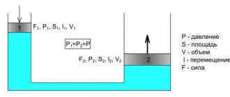
Hydraulics, purpose
Hydraulic systems operate by filling and emptying the working chambers of hydraulic cylinders, and also by the fact that the liquid does not compress and does not change its volume. In modern mechanical engineering, hydraulic systems are used in one form or another on all vehicles.
First of all, these are the brakes. Every car has them, and everywhere they are hydraulic; they work by creating brake fluid pressure in the line. Clutch drives work on the same principle.
The next hydraulic unit is shock absorbers, and although gas-filled shock absorbers and struts are increasingly being used, hydraulic shock absorption systems are in no hurry to lose their positions.
And, of course, power hydraulics in cranes, excavators, lifts and dump trucks. Here everything is somewhat more complicated, although the principles of operation are the same. It’s just that everything is somewhat larger and the pressure in the system is not created from the efforts of one leg, but is pumped by a special pump.
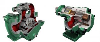
Components and elements of the hydraulic system
So what does a hydraulic system consist of? First of all, the most visible part of the system is the hydraulic cylinder. A unit whose efforts set various mechanisms in motion with enormous force.
There are two types of cylinders:
- Having a working stroke only in one direction, for example, working to lift the body. And such cylinders are brought to their original position due to the weight of the body itself.
- Having a working stroke in two directions. A living example of such cylinders is an excavator bucket. After all, you need to not only lift it, but also scoop up the rock with it, and this is a movement in the opposite direction.
The second visible and significant part of any power hydraulic system is high-pressure hoses (HPH). Working fluid passes through such hoses under high pressure, so you can’t install just any hose here.
Not all metal tubes can withstand such pressure. But you can’t install pipes everywhere, because in most cases the cylinder is movable, which means the supply of the working fluid must be elastic or flexible.
That’s why high-pressure hoses are used to connect the working cylinders to the hydraulic line.
The next visible component is the distribution box - the hydraulic control panel. On modern trucks and vans, this remote control is especially clearly visible, like a box on the side with a lot of levers.
Each lever controls two valves that distribute the working fluid between the chambers of one cylinder. And depending on which direction you tilt the lever, the cylinder will move in the same direction. The cylinder rod will either come out or, conversely, hide. This means that the crane boom or support column will either rise or fall.
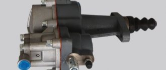
The hydraulic system also has invisible parts. The most important of them is the pump, which creates pressure of the working fluid in the entire system. The operation of the entire mechanism depends on its proper operation, because if the pressure is below normal, you will no longer be able to lift this or that load or scoop up soil with an excavator bucket.
The hydraulics also have their own tank. The container in which the working fluid is located is hydraulic oil before the pump takes it into operation and after the check valve returns it back. The oil level also needs to be constantly monitored. After all, if it becomes lower than normal, the cylinder rod will not be able to reach its full length, which means the force, power, and the entire unit will decrease.
How hydraulics work
And so let’s look at the operation of a cylinder on an excavator bucket.
The cylinder rod works in two directions, which means there is a working chamber on each side of the piston, inside the cylinder. A high-pressure hose is connected to the cylinder on each side.
- You moved the lever away from you on the control panel. The pump drove oil from the tank through hoses and high-pressure pipes to the bottom of the cylinder. Pressure was created in the lower working chamber, which pushed the piston, and therefore the rod, out of the cylinder. The rod came out, the bucket opened into the working position, and prepared to be grabbed.
- You brought the bucket to the place in the pit or quarry from which you need to scoop up soil. Now you need the bucket to scoop, so you move the previous handle on the remote control towards you. One valve in the control panel closed and another, the reverse one, began to open. The liquid now enters the top of the cylinder. The piston goes down and squeezes oil out of the lower chamber through the check valve, back into the tank, from where the pump drives it into the upper chamber. The rod goes into the cylinder, the bucket scoops up soil.
- You bring the bucket with soil to the place where you want to dump the soil. This could be a spoil heap or the body of a car. And again pull the lever towards you. The oil flows, pressure is created, the bucket opens, and the soil rushes to the unloading site.
Special devices, tools and equipment for hydraulic system diagnostics
In a hydraulic system, pressure is usually measured by a pressure gauge or vacuum gauge, and flow by a flow meter. devices and tools may be useful for a diagnostic specialist
- pressure transducer and recorder - if the accuracy of pressure measurement must be higher than the accuracy provided by the pressure gauge, and also if it is necessary to measure pressure during a transient process or under the action of reactive disturbances from an external load (the pressure transducer produces an alternating voltage depending on the applied pressure);
- graduated vessel and stopwatch - when measuring very small flows, such as leaks, they can be used to obtain greater accuracy than when measuring with a flow meter;
- temperature sensor or thermometer - to measure the temperature in the hydraulic tank, you can install a temperature sensor (often combined with a working fluid level indicator), and it is recommended to use a sensor that generates an alarm as soon as the temperature of the working fluid becomes too low or too high;
- thermocouple - for measuring local temperature in the system;
- Noise Meter - Increased noise is also a clear sign of a faulty system, especially for the pump. Using a noise meter, you can always compare the noise level of a “suspect” pump with the noise level of a new pump;
- particle counter - allows you to determine the level of contamination of the working fluid with a high degree of reliability.
Pressure losses in power lines
In the pipeline, the pump - spool block - cylinder cross-sectional areas have different values, so we represent the speed of the working fluid in the form of flow rate. Pressure losses were determined by the difference in pressure at the inlet and outlet of the spool block and in the cylinder cavity.
In the spool block, the pressure drop in the lines of the handle, bucket and boom is 1.8 MPa when operating from two pumps. At operating digging speeds, the pressure loss in the spool block reaches 0.4 MPa.
For the lines of the piston cavities of the boom, arm and bucket cylinders, the losses have similar values and do not exceed 1.5 MPa at maximum cylinder rod speeds. The pressure loss in the pipelines of the rod cavities of the bucket cylinders is 1.8 times greater than in the handle cylinders. During the digging process, the total losses in the lines of the bucket cylinders are 0.3 - -0.6 MPa, in the handle cylinders - 0.35 - 0.5 MPa. When operating at maximum speeds - modes of lifting the bucket for unloading and lowering it into the face, the losses will be 3 and 4.5 MPa for the bucket, 3 and 3.3 MPa for the handle, respectively.
JCB Backhoe Loader Hydraulic Manual
The hydraulic system of the backhoe loader ensures the full functioning of the working machine. Thanks to hydraulics, it becomes possible to operate attachments: a bucket, front and rear booms, a hydraulic hammer, a snow blower and other equipment. The hydraulic system consists of a huge number of elements that are closely interconnected and can only function effectively in combination. Failure of any unit can result in downtime.
Operating principle of an excavator hydraulic system
There is a hydraulic system on any type of excavator. In Ukraine you can purchase special vehicles:
- single-bucket and multi-bucket;
- tower;
- draglines;
- chain;
- rotary – compact and conventional;
- milling;
- trenching.
A set of interchangeable attachments allows you to transform equipment from one type into another and expand its functionality in the shortest possible time. This alone can significantly increase the demand for excavator services and the profit of the machine owner.
The hydraulic system works like this:
- the diesel drive motor rotates the shaft of the pumping hydraulic device, which in turn transforms mechanical energy into hydraulic energy;
- the liquid medium, moving through the pipeline, is directed to the hydraulic motor or cylinders, enters them through the control valves and is converted into mechanical energy or reciprocating motion;
- the working fluid, having completed the work, is drained into the hydraulic lines, returned to the tank, and then supplied to the pump;
- the steps are repeated in the next cycle.
For the normal functioning of the excavator hydraulic system, it is important to meet several conditions. Firstly, entrust the design and installation of units to professionals. Deviations during installation can cause incorrect operation of one or more components, entire hydraulics and the machine as a whole. Premature wear and increased resource consumption and decreased productivity are also possible. The second point is to transport the excavator to the work site with a trawl, and not under its own power. The third condition is to regularly carry out technical inspections strictly according to the schedule developed by the manufacturer, carry out maintenance and timely repairs, use original spare parts and high-quality fuels and lubricants. The fourth point is to involve only experienced specialists - foremen and operators, and follow recommendations and instructions regarding operating conditions and modes.