Often, the operating efficiency of MTZ 80(82) wheeled tractors as part of mounted tillage and seeding units decreases as a result of increased humidity or the physical condition of the soil. The main factors influencing productivity are the low coefficient of adhesion of the driving pneumatic wheels of the tractor with the surface being processed as a result of the general redistribution of the total weight to all support points of the unit. To increase the operating efficiency of universal row-crop tractors in units with soil-cultivating mounted implements, the hydraulic mounted system is equipped with additional loaders for the adhesion weight of the drive wheels.
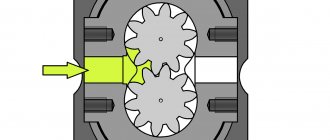
Operating principle of the additional loader
The device allows you to redistribute part of the counterforce of the cultivated soil and the weight of the mounted implement used to the rear wheels of the tractor, providing the most effective traction force while minimizing slippage.
Mechanical additional loading
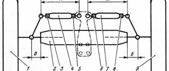
A mechanical solution for additional loading of the rear wheels was implemented in the designs of the rear linkages of early versions of MTZ wheeled tractors, as well as as part of the linkages of the YuMZ-6, T-40, T-25 tractors. Adjustment of additional loading is carried out by changing the position of the angle of the central link of the three-point hitch, where the linkage of the hinged linkage on the tractor has several vertically located mounting holes. Increasing the angle between the central link and the soil surface line by changing the upper attachment point of the link to the lower one in the tractor hitch ensures a redistribution of the total weight and resistance force of the unit to the rear wheels, while the weight force on the attachment is reduced.
Mechanical loader
The disadvantage of mechanical adjustment is the inconvenience in which, in order to adjust the unit, you need to experimentally select the position of the front end of the central link of the hitch.
Hydraulic additional loading
The operation of the hydraulic additional loader of the coupling weight (GSV) of the MTZ 80 tractor is to automatically create a dosed pressure in the lifting cavity of the hitch hydraulic cylinder. Thus, a small lifting force is transmitted through the hydraulic cylinder rod to the central link of the hitch, ensuring the transfer of the weight of the mounted implement and part of the resulting resistance force during processing to the rear wheels.
Hydraulic grip weight increaser for Belarus tractor
The use of a hydraulic loader increases the load on the rear wheels of the tractor from 11 to 37%, which provides an increase in traction force by 7-28%. In the operation of the GSV, by increasing the pressure in the pressure rise cavity by 0.1 MPa, the traction resistance of the processing equipment decreases by 25%. At the same time, wheel slip is reduced, tire wear is reduced, fuel consumption is reduced, processing speed and overall unit performance are increased.
GSV device of the MTZ 80 tractor
The hydraulic unit is built into the hydraulic mounted separate-module system of the tractor. The hydraulic loader includes:
- Control unit (regulator) - fixed to the hydraulic system housing
- Hydraulic accumulator - installed on the left housing of the rear wheel axle shaft
Placement of the hydraulic booster on the body of the hydraulic system of the MTZ 80 tractor
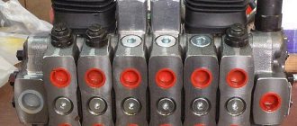
Regulator
The control unit is a regulator-hydraulic distributor with a mode control handle and a handwheel for adjusting the boost pressure in the hitch cylinder. Standardly, the lever is moved out by the fourth lever together with three control handles for the distributor sections and is pivotally coupled with the linkage control lever. The adjustment flywheel is located outside the tractor steering column casing.
FGP regulator
An automatic pressure control spool with an adjustment handwheel is installed in the upper part of the additional loader body. In the lower bore of the housing cavity there is a mode switching slider, the outer lever of which is used to control it. A check valve is installed in the housing between the two bores of the spool and the slide, and a shut-off valve is installed in the lower part of the assembly.
According to the modes, the shift lever can be set in four positions:
- GSV is turned off – the second position from the uppermost
- GSV is on – the second position from the lowest
- Locked - uppermost position
- Pressure Release - Lowest Position
Three positions of the lever are held by ball detents. The “pressure release” position is held only forcibly by the tractor driver’s hand when compressing the return spring.
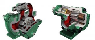
Hydraulic accumulator
The unit creates a pressure potential for constant support of oil pressure in the hydraulic cylinder of the hitch (in the lifting direction) when the GSV is turned on. The battery is a cylindrical body with a piston located inside on a rod along which a spring-loaded cylinder slides. The pressure on the piston coming from the system line compresses the accumulator spring. The potential of the compressed spring, in turn, provides oil pressure for support in the corresponding cavity of the hydraulic cylinder of the tractor hitch.
Hydraulic accumulator device
Details of the hydraulic accumulator of the MTZ 80 additional loader
Recommendations for the use of FGPs
When using FGPs, you must adhere to the following recommendations:
First of all, the maximum possible back pressure is adjusted by twisting the flywheel counterclockwise until it stops;- At the beginning of the rut, the hydraulic intensifier handle is set to the “Pressure Relief” position and the spool regulator on the main cylinder is moved to the “Lift” position, since it is locked in relation to the hydraulic intensifier. In this position, the GSV handle is held until the working tool plunges into the ground, after which it is smoothly released - it will automatically move to the “On” position;
- At the end of the rut, the implement is transferred to the transport position, for which the GSV handle is moved to the “Off” position. Since the distribution handle was previously set to the “Lift” position, the implement will rise;
The backing pressure during plowing is adjusted during the first 2-3 passes until the plow proceeds to plowing to the maximum depth; during cultivation or sowing, adjustment is carried out during the first pass. In the process of subsequent work, pressure adjustment is not required, until the transition to a new field or the complete dulling of the working elements;- In areas with high soil density, the handle is moved to the “Pressure Release” position, which increases the cultivated depth. It returns to its normal position when leaving a dense area of soil;
- When transporting or using trailed machines, the GSV handle is moved to the “Locked” position, which eliminates the possibility of lowering the attachment.
Control and operation of the hydraulic loader
If the rear wheels are insufficiently loaded and slipping occurs when the tractor is operating with land-cultivating equipment, to adjust the back-up pressure, the GSV flywheel is turned counterclockwise until it stops, thus blocking the flow of oil from the discharge cavity of the regulator into the drain line of the system hydraulic tank. The control lever for the hydraulic cylinder of the main distributor of the hydraulic system is moved to the “lift” position, and the control handle to the “GSV on” position. Thus, the lifting cavity of the hydraulic cylinder is connected to a hydraulic accumulator, which creates a slight supporting pressure.
Scheme for connecting the GSV to the tractor’s hydraulic linkage system
When the device is turned on, evidence of the operation of the additional loader is the appearance of the possibility of slowly lifting the hitch by hand (without attached attachments). With the implement mounted, the activation of the additional loader will be visually indicated by the appearance of a slight rise in the central link from the force of the attachment hydraulic cylinder.
Directly during operation of the unit, if the back-up pressure in the cylinder is too high and lifts the support wheel of the attached equipment from the surface of the field (the equipment is being deepened), rotate the flywheel clockwise to reduce the back-up pressure.
Operating mode of additional loading
Oil from the distributor is directed to the top of the regulator. The automatic control spool is held in a certain position depending on the forces acting on it: on the right side, by the tension of the adjustment spring 8 and the safety valve spring 6, on the left side, by the influence of oil pressure from the large plunger 2.
On position
In the case when the pressure in the “accumulator-hydraulic cylinder” system corresponds to the adjusted one, the spool moves to the right, forming a free passage between the spool neck and the belt of the regulator body to drain oil from the distributor into the tank. This ensures that the pump operates without pressure, and part of the weight of the mounted machine in the working position is transferred by the hydraulic cylinder to the drive wheels from the pressure potential created by the hydraulic accumulator.
When the back pressure drops as a result of oil seeping through the piston seals or as a result of an increase in the volume of the lifting cavity of the hitch cylinder, springs 8 and 6 overcome the reduced force on the spool from the side of plunger 2 and move it to the left. In this case, the passage of oil into the tank is blocked and pressure is supplied to the accumulator through check valve 23 to restore the potential of the boost pressure in the cylinder. After reaching the set pressure, the oil moves the spool to the right, opening a passage into the drain line to the system hydraulic tank.
The back-up pressure is adjustable within 0.8-2.8 MPa and depends on the degree of tension of springs 6 and 8 as part of the GSV regulator.
When the pressure in the line “accumulator - cylinder cavity” increases by 0.8-1.5 mPa from the adjusted pressure value due to a decrease in the volumetric lifting cavity in the cylinder (for example, when copying the relief with attachments), safety valve 3 will open and release excess oil into the tank.
“GSV off” position
In this position of the slider, the working fluid supplied by the distributor spool to the hydraulic cylinder of the hitch passes through the slider 24 and the shut-off valve 28, bypassing all the regulator lines. In the “GSV off” mode, the hitch is controlled only through the distributor.
Off position
The additional loader is switched to the off mode if it is necessary to deepen the attachments at the end of the headland of the cultivated field before turning the unit. When switched off, pressure flows through the distributor section set in the lifting position into the corresponding cavity of the cylinder and, after the equipment is fully raised, it automatically moves to the neutral position of the spool of the main distributor section.
Locked position
The regulator slider occupies the extreme left position, and shut-off valve 28 is pressed by the spring and oil pressure in the cylinder to the edges of the sleeve pressed into the regulator body. In this case, the valve disconnects the pressure cavity of the cylinder from the hydraulic system, eliminating the leakage of working fluid through the gaps of the spool pairs of the hydraulic intensifier and distributor.
Locked position
The “Locked” position is used when it is necessary to secure the unit in the transport position for a long move.
Pressure release
The reset is carried out by forcibly holding the regulator handle by the tractor driver in the lowest position. In this case, the additional loader slider occupies a non-fixed extreme right position, ensuring the connection of the hydraulic cylinder cavity through an open shut-off valve, drillings and flats on the slider and holes in the housing with a drain. The pressure in the cylinder is equal to the drain pressure, which is identical to the “Floating” mode. The FGP battery is not connected to the drain. Oil from the distributor enters the cavity of spool 5 of the hydraulic intensifier and is transferred to the drain (if necessary, it is supplied to charge the hydraulic accumulator).
Pressure release
Pressure release is used to lower the hitch when installing the equipment into the working position.
Hydraulic grip weight increaser device
The automatic device for hydraulic additional loading of the drive wheels of the MTZ-80 (MTZ-82) tractor consists of an automatic pressure regulator with a charger, a control mechanism and a spring hydraulic accumulator.
The pressure regulator and the control mechanism for the hydraulic traction weight increaser are made in one unit, which is installed in the front part of the cabin next to the distributor.
Rice. Design of the hydraulic adhesion weight increaser: 1 - body; 2 - large plunger; 3 - safety valve; 4 - spool; 5 — safety valve spring; 6 - nut; 7 - small plunger; 8 — adjusting spring; 9 — figured nut; 10 - bolt; 11 — adjusting bolt; 12 — front cover; 13 - sealing ring; 14 — handwheel; 15 — outer lever; 16 — internal lever, 17 — axis of levers; 18 - separator; 19 - ball; 20 — clamp clip; 21 — slider spring; 22 — slider; 23 — shut-off valve ball; 24 — shut-off valve spring; 25 - fitting; 26 — valve pusher; 27 — back cover; 28 - check valve.
The hydraulic traction weight increaser for the MTZ-80 (MTZ-82) tractor consists of a housing 1, cast from cast iron and closed on both sides with covers 12 and 27. In the upper part of the housing 1 there is a spool 4, loaded with a spring 8 and moving along the axis along a large plunger 2 The tension of the spring 8 is adjusted using a nut 9. A safety valve 3 is installed inside the spool, pressed to its seat by a spring 5, the tension of which is regulated by a small plunger 7, moved along its axis together with a shaped nut 9 when the adjusting bolt 11 is rotated by a flywheel 14. Safety valve 3 is adjusted so that it opens at a pressure exceeding 0.8–1.5 MPa (8–15 kgf/cm2) the pressure in the hydraulic accumulator. In the lower part of the housing 1 there is a check valve 28, a slider 22 with a spring 21 and a locking device, an internal lever 16 and a shut-off valve 23.
Outside the hydraulic intensifier housing there is a control lever 15 with a handle and a screw shank 11 with a handwheel 14. Four fittings are screwed into the housing 1, to which pipelines are connected connecting the hydraulic intensifier with other units and units of the hydraulic mechanism of the tractor's mounted system.
The hydraulic intensifier of the MTZ-80 (MTZ-82) tractor differs from the hydraulic intensifier of the MTZ-50 (MTZ-52) tractors only in the design of the slider, which, instead of the “Locked”, “Off”, “On” positions, also has a “Pressure Relief” position.
The “Pressure Relief” slider position was introduced in order to block the hydraulic booster handle and the spool handle (which controls the operation of the main power cylinder) of the tractor hydraulic system distributor. This locking makes it possible, at the beginning of the run, when setting the hydraulic booster handle to the “Pressure Relief” position and holding it in this position, to deepen the mounted machine under the influence of its own weight and at the same time automatically set the control handle of the main power cylinder of the distributor to the “Lifting” position. This position of the hydraulic intensifier slide is equivalent to the floating position of the distributor spool. When you remove your hand from the handle, the hydraulic booster slider automatically takes the “On” position, since the slider is not fixed in the “Pressure Relief” position and returns to the “On” position.
Rice. Diagram of operation of the hydraulic system of the MTZ-80 (MTZ-82) tractor with a hydraulic coupling weight increaser: 1 - pump; 2 — tank for working fluid; 3, 5, 7, 9, 11 and 12 - pipelines connecting hydraulic system units; 4 — spring accumulator; 6 — hydraulic booster; 8 - cylinder; 10 — distributor, position of the hydraulic booster handle. I - “Locked”; II - “Off”; III - “On”; IV - “Pressure release”; A, B, C, D, D, E, G, 3, I, K - cavities.
The discharge cavity A of the hydraulic booster is connected by pipeline 12 to the discharge fitting of the distributor 10 of the tractor hydraulic system, designed to connect the working cavity of the main power cylinder when there is no hydraulic booster. The cavity of the shut-off valve E of the hydraulic booster is connected through pipeline 7 to the working cavity I of the main power cylinder 8. The drain cavity D of the hydraulic booster is connected via drain pipeline 3 to the drain pipeline running from the drain cavity of the distributor 10 to tank 2 of the hydraulic system. The cavity F of the check valve through a drilling in the spool 3 is connected by a pipeline 5 to the working cavity of the spring accumulator 4.
The spool assembly with a large plunger, spool spring, figured nut and adjusting screw acts as an automatic device for recharging the hydraulic accumulator and supplying the main power cylinder with working fluid during operation of the mounted unit.
The slider serves to include the hydraulic booster in the hydraulic system of the tractor and disconnect it from the hydraulic system, to disconnect the main power cylinder from the hydraulic system of the tractor during the transport position of the mounted machine during moves, and to relieve the hydraulic system and hydraulic booster from pressure during the period of deepening the mounted machine under the influence of its own weight.
The safety valve of the hydraulic booster is designed to prevent an excessive increase in pressure in the working cavity of the hydraulic accumulator 4 compared to the specified one.
Hydraulic accumulator 4, which uses an energy storage element in the form of a cylindrical spring, serves to compensate for leaks and create support in the working cavity of the main power cylinder within the degree of insensitivity of the recharging machine.
Rice. Spring accumulator: 1 - bolt; 2 — front cover; 3 - cylinder; 4 - casing; 5 - spring; 6 — rod; 7 — protective ring; 8 - piston; 9 - sealing ring; 10 — plug for draining leaks of working fluid.
The spring accumulator consists of a cylinder 3, a piston 8, a hollow rod 6, a spring 5 and a casing 4, closed at the front end with a cover 2, and at the rear - with a bottom welded to the casing.
The cylinder assembly with a coil spring is placed in a casing and closed with cover 2. The piston rod is fixed rigidly in the front cover. A fitting is screwed into the end of the rod for supplying working fluid to the hydraulic accumulator. When charging, the working fluid enters through the fitting and the axial through hole of the rod into the cavity between the piston and the bottom of the cylinder.
Under the pressure of the working fluid, the cylinder moves away from the cover 2, compresses the spring 5 and thereby accumulates energy. At the bottom of the accumulator casing there is a hole for draining accumulated leaks of working fluid. This hole is closed with plug 10. A bracket with four holes for attaching the hydraulic accumulator to the rear axle housing is welded to the casing. The mass of the hydraulic accumulator without working fluid is 5.6 kg.
From the diagram of the hydraulic mechanism of the mounted system of the MTZ-80 (MTZ-82) tractors with a hydraulic adhesion weight increaser, it is clear that the working fluid from tank 2 enters pump 1, and then is pumped into the pressure cavity of the distributor 10 of the tractor hydraulic system. The further movement of the working fluid depends on the positions of the valve spools in the distributor housing 10. When operating a hydraulic system without a hydraulic intensifier, the positions of the valve spools of the P75-VZ-A distributor are used. It must be remembered that on the MTZ-80 (MTZ-82) tractors the distributor does not have the spools locked in the “Lowering” position, and to force the lowering of the working bodies of an agricultural machine, it is necessary to hold the distributor lever with your hand until the working bodies are buried in the soil.