How does a hydraulic drive work?
Let us show the structure of hydraulic equipment in the diagram. The drive operates on the principle of a lever under pressure, that is, by applying a small force, a large force is obtained.
In the diagram, the pressure on the second piston is determined by the formula:
The force on the lever depends on the size of the pressure area. The larger the area of the second piston compared to the area of the first, the more its force will increase, indicated by markers F1 and F2. But while gaining leverage in terms of pressure, you have to sacrifice freedom of movement. This omission in the design was eliminated with another invention - a check valve.
This term refers to a unit that blocks the flow of oil moving in one direction to freely allow flow from the opposite direction. The diagram with this element of hydraulic equipment looks like this:
Let's start the cycle. Let's apply a force to the first piston and force it to move a distance, say, I1. Accordingly, the second piston will move from its position by a certain distance. When we return the first piston back, the liquid flow will not flow out after it due to the action of the check valve, and the second piston will be motionless. Let's repeat the cycle by adding liquid from the tank to the chamber with the first piston and applying force to it. Although piston 1 will move again the same distance I1, piston 2 will now travel twice the distance relative to its original location.
So, by increasing the number of cycles, you can obtain more and more force from the second piston, forcing it to move further and further from its original position.
It is for this device that hydraulic equipment is ahead of mechanical drive. Where mechanics fail, hydraulic systems are able to produce significant pressure with less energy.
Hydraulic system components
Main components
The hydraulic system consists of many parts. The main parts are the pump and the drive. The pump supplies oil by converting mechanical energy into pressure energy and kinetic energy. An actuator is part of a system that converts hydraulic energy back into mechanical energy to perform work. Parts other than the pump and drive are required for the hydraulic system to fully operate.
Tank: oil storage
Valves: control the direction and amount of flow or limit pressure
Pipe lines: connection of system parts
Let's look at two simple hydraulic systems.
Example 1, hydraulic jack
What you see in the picture is called a hydraulic jack. When you apply force to the lever, the hand pump forces oil into the cylinder. The pressure of this oil presses on the piston and lifts the load. The hydraulic jack is in many ways similar to the Pascal hydraulic lever. A hydraulic tank has been added here. A check valve is installed to keep oil in the tank and cylinder between strokes of the piston.
In the top picture, the pressure is held, the check valve is closed. When the pump handle is pulled up, the inlet check valve opens and oil flows from the tank into the pump chamber.
Then the pump handle moves down. Oil pressure closes the inlet check valve but opens the outlet check valve. At the same time, oil enters the cylinder and presses the piston from bottom to top.
The bottom picture shows the open shut-off valve to connect the tank and cylinder, allowing oil to flow into the tank while the piston moves down.
Example 2, hydraulic cylinder operation
1. First, there is a hydraulic tank filled with oil and connected to a pump.
2. Next, a pump is needed to create flow, but the pump does not suck oil from the tank. Oil enters the pump under the influence of gravity.
3. The pump is running and pumping oil. It is important to understand that the pump only moves volume. Volume sets the rate of hydraulic action. The pressure is created by the load and not created by the pump.
4. The hose from the pump is connected to the distribution valve. Oil flows from the pump to the valve. The operation of this valve is to direct flow either to the cylinder or into the tank.
5. The next step is the cylinder, which does the actual work. Two hoses from the control valve are connected to the cylinder.
6. Oil from the pump is directed to the lower cavity of the piston through the distribution valve. The load causes resistance to flow, which in turn creates pressure.
7. The system looks complete, but it is not. Another very important detail is needed. We must know how to protect all components from damage in the event of a sudden overload or other incident. The pump continues to operate and supply oil to the system even if an incident occurs to the system. If the pump supplies oil and there is no way for the oil to escape, the pressure increases until a part breaks. We install a safety valve to prevent this. Usually it is closed, but when the pressure reaches the set value, the safety valve opens and oil flows into the tank.
8. Tank, pump, control valve, cylinder, connection hoses and safety valve are the core of the hydraulic system. All these details are necessary.
Important Terms
Let's define some concepts and elements that make up the hydraulic system.
- The unit indicated in the diagram as piston 1 + chamber + check valve is called a pump.
- Piston 2 in hydraulics is designated as an engine or a hydraulic cylinder.
These elements will be described in more detail in the next section.
The main conclusion of the section: the design and operation of the hydraulic system are subject to a cyclic process of creating force, recoil and the next cycle, due to which the drive is capable of creating titanic pressure.
Working cylinder, hydraulic motor, hydraulic throttle
This is where the main energy conversion process takes place. The oil flows in one or two directions, causing the cylinder to differ in its mode of action (one-way or two-way).
Happens:
- with piston action;
- telescopic action;
- plunger
Complex machines sometimes have a hydraulic motor instead of a cylinder. Thanks to it, the oil first comes from the pump, then goes back through the pipelines, and the remainder is drained into a storage tank.
In the design of hydraulic equipment, the hydraulic throttle plays the role of a fluid supply speed regulator. This regulates the speed of movement of the cylinder and engine. The structure of this element is shown in the diagram below.
Chokes are sensitive to the brand, type of oil used, as well as ambient temperature. At a temperature of 30 C+, low viscosity oils are used. In this case, the jet holes are in the range of 2-2.5 mm. For winter conditions, install jets with holes of at least 3.5 mm.
Hydraulic systems and energy
Hydraulic systems
Hydraulic systems are used to transfer mechanical energy from one place to another. This happens through the use of pressure energy. The hydraulic pump is driven by mechanical energy. Mechanical energy is converted into pressure energy and kinetic energy of the hydraulic fluid and then converted back into mechanical energy to do work.
Energy Conversion Value
The energy that is transferred to the hydraulic system is converted from the mechanical energy of the engine, which drives the hydraulic pump. The pump converts mechanical energy into fluid flow, converting mechanical energy into pressure energy and kinetic energy. The fluid flow is transmitted through the hydraulic system and directed to the cylinder and motor drives. The pressure energy and kinetic energy of the fluid causes the actuator to move. With this movement, another transformation into mechanical energy occurs.
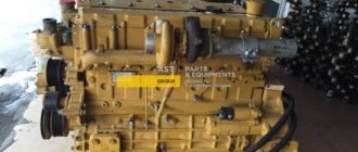
How it works in a hydraulic excavator
In hydraulic excavators, the primary mechanical energy from the engine drives a hydraulic pump. The pump directs the flow of oil into the hydraulic system. When the drive moves under the influence of oil pressure, it is again converted into mechanical energy. The excavator boom can be raised or lowered, the bucket moves, etc.
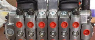
Hydraulic distributors
They are used to control fluid flows from the pump to the hydraulic cylinder cavity, and then drain excess fluid into the tank. There are two-three-position, one-two-three-spool valves. Two-position is so called because the lever is moved to one position (position) to activate the cylinder.
Spool-type hydraulic distributors have become widespread as unpretentious, reliable, easy to operate, and small-sized.
Valves
Units that regulate various flow characteristics: start-stop, intensity. They are divided into proportional and servo-driven. A safety valve is used to balance the fluid pressure in the cylinders. It comes in direct and differential action. The purpose of its work is to balance the pressure by compressing and expanding the spring. The spring stroke is adjusted with a screw.
The arrow indicates a direct-acting safety valve, next to it is a differential one. The operating principle is based on two pressure stages, due to which the frequency of operation of the spool is reduced.
Tools in hydraulics
Hydraulic tools refer to special power units used for general installation and repair work that provide the highest possible force in the smallest space.
Their features:
- ease of use;
- clarity of the program;
- high strength;
- fast delivery;
- versatility of application.
Hydraulic components are used more for complex tasks. With their help, it is possible to accomplish a specific goal with maximum accuracy.
The scope of application involves installation in:
- machines where cylinders, hand and motor pumps perform specified functions;
- devices, tools for clamping, mounting, pressing, cutting, riveting, pipe pulling, etc.;
- frame presses, lifting devices.
The classification is based on aspects of use. Scope of application: construction, industry, extraction of natural mineral resources.
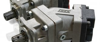
Pumps
Thanks to this element, mechanical energy is converted into fluid pressure. There are many varieties of this group of elements on the market, adapted for specific operating conditions. For example, dynamic pumps are designed for harsh operating conditions of complex machines and mechanisms, as well as with a reduced noise level.
Hydraulic drive [up]
Hydraulic drive is a device designed to drive machines and mechanisms using hydraulic energy.
An integral part of the hydraulic drive is a hydraulic mechanism that operates under pressure and has one or more volumetric hydraulic motors.
Hydraulic drive devices include
- hydraulic machines
- hydraulic devices
- hydraulic lines
- hydraulic capacity
- working environment conditioners
For example, in domestic hydraulics, a popular hydraulic drive for a large number of varied equipment is the GST-90 and GST-112.
Advantages, disadvantages of hydraulic equipment
Pros:
- the ability to regulate the rotation speed in a stepless manner;
- independent location of nodes;
- Requires fewer parts to operate than a mechanical drive. An actuator and a pump with a hydraulic motor are sufficient for coordinated operation;
- overload protection;
- standard elements of the hydraulic drive circuit simplify the process of replacement and repair.
However, there are disadvantages:
- operating efficiency depends on the temperature level;
- Part of the working pressure is spent on fluid friction;
- there is a risk of liquid leaks;
- Air may be released from the liquid, affecting the pressure force.
Hydraulic equipment requires regular maintenance at least once every 2 years.
Control system
Machine control systems are designed to power control the movement of working parts or control the operating mode of the engine, clutches, brakes, gearbox and other drive elements.
The requirements for machine control systems are to ensure that the mechanisms are controlled with minimal nervous and physical effort by the driver (operator) and ensure maximum machine performance.
Control of the power plant and the machine as a whole is associated with the regulation of several parameters, which are combined for convenience. Such units are control panels, the mechanisms of which are kinematically interconnected. They are usually installed in the driver's cab.
High demands are placed on the design of the driver's cabin and control panels. In particular, the location of the driver’s seat relative to the handles, levers and pedals, their relative placement, as well as the comfort of the cabin and the viewing angles are extremely important.
The control system is classified according to the following main characteristics:
– method of transmitting energy to the actuator – mechanical (lever and rope-block), hydraulic, pneumatic, electric and combined;
– energy source – the muscular energy of the driver or the main (auxiliary) power unit;
– principle of operation – manual and automatic.
A mechanical linkage system is used to control levers (operated by pedals and handles), clutches and brakes. The normal force on the levers is no more than 30-40 N with a stroke of 25 cm or less, and on the pedals no more than 80 N with the same stroke. The force applied to the handle or pedal is increased through the transmission levers and transmitted to the actuators.
Figure 2.7 shows the control of the band brake from the handle. .
Figure 2.7 – Lever control system /1/
Lever movement – 1
through the adjusting rod -
2
and lever -
3
it is transmitted to the pusher -
4
, which, through the lever -
5
, tightens the tape -
6
. This type of control is simple in design, convenient for maintenance, but tiring for the operator due to the relatively large efforts required to move the handles and pedals.
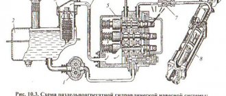
of hydraulic control systems - pumping and pumpless. In the first case, the working pressure of the hydraulic system fluid is created by a pump, in the second - by the muscular force of the operator.
Pumpless systems
controls are usually used to control mechanisms that require the greatest sensitivity and smooth operation - brakes, for example. These systems do not significantly reduce the force on the levers and pedals compared to lever mechanical control systems.
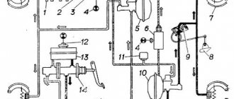
Hydraulic pumpless control systems (Figure 2.7) have two cylinders: command - 8
and executive –
5
, connected by pipeline –
6
.
Figure 2.7 – Hydraulic pumpless control system /1/
Cylinder diameters d
1 and
d
2 are selected so that with a small force and a large stroke on the control pedal, a large force and a small stroke are obtained on the rod -
3
of the actuator cylinder -
5
.
When you press the pedal - 12
with a locking latch -
11
the cam rotates around its axis and acts on the cylinder piston -
8
through a system of adjusting rods. The piston squeezes part of the working fluid from the command cylinder into the executive cylinder.
Under the influence of working fluid pressure, the piston - 4
moves to the left, presses on the rod -
3
, connected by levers to the brake band
1
.
When the load is removed from the pedal, the return spring – 7
returns the pedal to its original position.
At the same time, the cylinder piston - 8
, under the action of a spring located inside, moves to the left, and the brake system levers, under the action of a return spring -
2,
are released from the pulley.
Possible leaks of working fluid are compensated by its flow from the tank - 9
with the shut-off needle -
10
.
Pumping
hydraulic control is fundamentally different from pumpless control in that the necessary force is created by a pump that supplies fluid under pressure to the actuator cylinder. This does not require much effort on the control levers, because the driver moves only the distributor spools connecting the actuator cylinders to the pump or drain tank.
One of the main indicators characterizing the operating mode of hydraulic pump control systems is the number of starts - per 1 hour. According to this indicator, operating modes are light - Z < 300, medium - Z = 300-700 and heavy - Z > 700.
The advantages of hydraulic control systems are the compactness and small size of the control panel, working cylinders and engines due to the use of significant pressures, the ability to transmit forces to remote points, and the absence of complex lever systems and hinge joints.
With hydraulic control, the force on the control levers and their stroke are significantly lower than with lever mechanical control. This reduces driver fatigue and increases productivity.
The disadvantages of hydraulic systems include the abruptness of the mechanisms, which causes the occurrence of dynamic loads, the need for special types of working fluids, and an increased class of precision in the manufacture of hydraulic equipment. At the same time, difficulties are observed when operating machines in cold and hot climates.
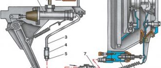
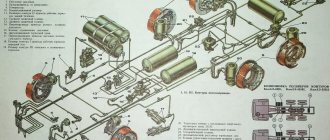
Pneumatic control systems differ from hydraulic ones in that they use compressed air instead of liquid (Figure 2.8).
Figure 2.8 – Pneumatic control system /1/
In this system, the compressed air from the compressor is 1
enters the oil and moisture separator -
2
and then into the receiver -
3
.
The air pressure in the system is monitored by a pressure gauge - 4
, and its excess is released by a safety valve - 5. Air from the receiver is directed to the distributors -
6
, and then to the working chamber -
10
and the pneumatic cylinder -
9
, which control the belt -
12
and block -
8
car brakes.
Working springs – 11
and –
7
return the working controls to their original position.
The advantage of pneumatic control is the simplicity of the design and the softness of the mechanisms. Its disadvantages are associated with the difficulty of cleaning the air from moisture and dust, as well as its low pressure - 0.7-0.8 MPa, which increases the dimensions of pneumatic units.
Electrical control systems are mainly used in machines with electric and diesel-electric drives. Electric drive control includes starting and stopping the electric motor, reversing it, changing the rotation speed and ensuring operational safety.
Electric motors with a power of up to 15 kW are switched on by controllers or magnetic starters; more powerful ones - with the help of magnetic contactor stations controlled by special command devices. With controller and contactor control, it is possible to regulate the shaft speed of asynchronous electric motors within certain limits.
The electrical system is compact in design, reliable in operation, and allows the use of automation.
Combined control systems are a combination of an electrical system with a hydraulic or pneumatic system. Their advantages are the use of remote control and the reduction in the length of the oil and air lines that make up this combined system.
Depending on the nature of the driver’s influence on the controlled mechanisms, control systems are distinguished between direct action and with amplifiers (servo drives). To the first
include mechanical lever and hydraulic pumpless control systems, the
second
- pneumatic, hydraulic pump, electric and combined systems.
In automated control systems
working bodies use hydraulic drive servo systems - a hydraulic system with feedback that provides power amplification.
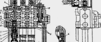
The design of a unified hydraulic steering wheel for pneumatic wheels was developed by VNIIstroymash (cited from /1/). The hydraulic steering wheel is a metering-type steering mechanism with feedback on the volume of working fluid and no connection with the turning mechanism of the machine (Figure 2.9).
Figure 2.9 – Scheme (a) and design (b) of a unified hydraulic steering wheel for pneumatic-wheeled vehicles: n, s, l, p – hydraulic lines for pressure, drain and turning wheels to the left and right /1/
The main parameter of the hydraulic steering wheel is the volume of working fluid (supply) supplied per revolution of the hydraulic steering shaft. For cars with low power hydraulic steering (Figure 2.9, a
) is made in the form of a monoblock design according to a modular principle and consists of three distribution block modules with a spool -
2
, a steering shaft -
1
and a screw differential device;
glider gearbox – 3
and dispenser –
4
.
A metering device, made in the form of a feedback hydraulic motor, allows the steering system to control the volume of working fluid supplied to the actuator cylinder. This ensures that the dosed volume of working fluid is proportional to the angular movement of the hydraulic unit shaft.
Such hydraulic steering wheels come in four standard sizes with supply volumes of 125, 250, 500, 1000 cm3. For machines of higher power, steering gears with a supply volume of 8000 cm3 are provided.
In recent years, microelectronics, microprocessors and on-board computers have begun to be used to automate medium- and high-power machines. In the automated control system of modern machines, the subsystem for monitoring the operation of individual units and components can provide verification of 20-30 parameters.
Controlled parameters are often divided into the following main groups: pre-start control; operational, constantly monitored during operation; diagnostic, making it easier to determine the causes of problems or indicating the need for maintenance or repair of the machine.
To pre-start
controls include the level of fuel, crankcase oil, working and coolant fluid, as well as the position of gears, clutches and transmission brakes.
In operational
The parameters are divided into warning and emergency. Emergency ones include the minimum oil pressure in engines, the maximum temperature of the coolant and working fluid, the maximum engine speed, the minimum fluid level in the clutch and brake control systems, in the hydraulic drive system tank, the minimum pressure in the brake lines, steering, the maximum roll of the machine relative to horizon, maximum voltage of the on-board network, etc.
The choice of specific controlled parameters when installing an on-board control and information system on a machine must be agreed upon with consumers.
Machine control systems are designed to power control the movement of working parts or control the operating mode of the engine, clutches, brakes, gearbox and other drive elements.
The requirements for machine control systems are to ensure that the mechanisms are controlled with minimal nervous and physical effort by the driver (operator) and ensure maximum machine performance.
Control of the power plant and the machine as a whole is associated with the regulation of several parameters, which are combined for convenience. Such units are control panels, the mechanisms of which are kinematically interconnected. They are usually installed in the driver's cab.
High demands are placed on the design of the driver's cabin and control panels. In particular, the location of the driver’s seat relative to the handles, levers and pedals, their relative placement, as well as the comfort of the cabin and the viewing angles are extremely important.
The control system is classified according to the following main characteristics:
– method of transmitting energy to the actuator – mechanical (lever and rope-block), hydraulic, pneumatic, electric and combined;
– energy source – the muscular energy of the driver or the main (auxiliary) power unit;
– principle of operation – manual and automatic.
A mechanical linkage system is used to control levers (operated by pedals and handles), clutches and brakes. The normal force on the levers is no more than 30-40 N with a stroke of 25 cm or less, and on the pedals no more than 80 N with the same stroke. The force applied to the handle or pedal is increased through the transmission levers and transmitted to the actuators.
Figure 2.7 shows the control of the band brake from the handle. .
Figure 2.7 – Lever control system /1/
Lever movement – 1
through the adjusting rod -
2
and lever -
3
it is transmitted to the pusher -
4
, which, through the lever -
5
, tightens the tape -
6
. This type of control is simple in design, convenient for maintenance, but tiring for the operator due to the relatively large efforts required to move the handles and pedals.
of hydraulic control systems - pumping and pumpless. In the first case, the working pressure of the hydraulic system fluid is created by a pump, in the second - by the muscular force of the operator.
Pumpless systems
controls are usually used to control mechanisms that require the greatest sensitivity and smooth operation - brakes, for example. These systems do not significantly reduce the force on the levers and pedals compared to lever mechanical control systems.
Hydraulic pumpless control systems (Figure 2.7) have two cylinders: command - 8
and executive –
5
, connected by pipeline –
6
.
Figure 2.7 – Hydraulic pumpless control system /1/
Cylinder diameters d
1 and
d
2 are selected so that with a small force and a large stroke on the control pedal, a large force and a small stroke are obtained on the rod -
3
of the actuator cylinder -
5
.
When you press the pedal - 12
with a locking latch -
11
the cam rotates around its axis and acts on the cylinder piston -
8
through a system of adjusting rods. The piston squeezes part of the working fluid from the command cylinder into the executive cylinder.
Under the influence of working fluid pressure, the piston - 4
moves to the left, presses on the rod -
3
, connected by levers to the brake band
1
.
When the load is removed from the pedal, the return spring – 7
returns the pedal to its original position.
At the same time, the cylinder piston - 8
, under the action of a spring located inside, moves to the left, and the brake system levers, under the action of a return spring -
2,
are released from the pulley.
Possible leaks of working fluid are compensated by its flow from the tank - 9
with the shut-off needle -
10
.
Pumping
hydraulic control is fundamentally different from pumpless control in that the necessary force is created by a pump that supplies fluid under pressure to the actuator cylinder. This does not require much effort on the control levers, because the driver moves only the distributor spools connecting the actuator cylinders to the pump or drain tank.
One of the main indicators characterizing the operating mode of hydraulic pump control systems is the number of starts - per 1 hour. According to this indicator, operating modes are light - Z < 300, medium - Z = 300-700 and heavy - Z > 700.
The advantages of hydraulic control systems are the compactness and small size of the control panel, working cylinders and engines due to the use of significant pressures, the ability to transmit forces to remote points, and the absence of complex lever systems and hinge joints.
With hydraulic control, the force on the control levers and their stroke are significantly lower than with lever mechanical control. This reduces driver fatigue and increases productivity.
The disadvantages of hydraulic systems include the abruptness of the mechanisms, which causes the occurrence of dynamic loads, the need for special types of working fluids, and an increased class of precision in the manufacture of hydraulic equipment. At the same time, difficulties are observed when operating machines in cold and hot climates.
Pneumatic control systems differ from hydraulic ones in that they use compressed air instead of liquid (Figure 2.8).
Figure 2.8 – Pneumatic control system /1/
In this system, the compressed air from the compressor is 1
enters the oil and moisture separator -
2
and then into the receiver -
3
.
The air pressure in the system is monitored by a pressure gauge - 4
, and its excess is released by a safety valve - 5. Air from the receiver is directed to the distributors -
6
, and then to the working chamber -
10
and the pneumatic cylinder -
9
, which control the belt -
12
and block -
8
car brakes.
Working springs – 11
and –
7
return the working controls to their original position.
The advantage of pneumatic control is the simplicity of the design and the softness of the mechanisms. Its disadvantages are associated with the difficulty of cleaning the air from moisture and dust, as well as its low pressure - 0.7-0.8 MPa, which increases the dimensions of pneumatic units.
Electrical control systems are mainly used in machines with electric and diesel-electric drives. Electric drive control includes starting and stopping the electric motor, reversing it, changing the rotation speed and ensuring operational safety.
Electric motors with a power of up to 15 kW are switched on by controllers or magnetic starters; more powerful ones - with the help of magnetic contactor stations controlled by special command devices. With controller and contactor control, it is possible to regulate the shaft speed of asynchronous electric motors within certain limits.
The electrical system is compact in design, reliable in operation, and allows the use of automation.
Combined control systems are a combination of an electrical system with a hydraulic or pneumatic system. Their advantages are the use of remote control and the reduction in the length of the oil and air lines that make up this combined system.
Depending on the nature of the driver’s influence on the controlled mechanisms, control systems are distinguished between direct action and with amplifiers (servo drives). To the first
include mechanical lever and hydraulic pumpless control systems, the
second
- pneumatic, hydraulic pump, electric and combined systems.
In automated control systems
working bodies use hydraulic drive servo systems - a hydraulic system with feedback that provides power amplification.
The design of a unified hydraulic steering wheel for pneumatic wheels was developed by VNIIstroymash (cited from /1/). The hydraulic steering wheel is a metering-type steering mechanism with feedback on the volume of working fluid and no connection with the turning mechanism of the machine (Figure 2.9).
Figure 2.9 – Scheme (a) and design (b) of a unified hydraulic steering wheel for pneumatic-wheeled vehicles: n, s, l, p – hydraulic lines for pressure, drain and turning wheels to the left and right /1/
The main parameter of the hydraulic steering wheel is the volume of working fluid (supply) supplied per revolution of the hydraulic steering shaft. For cars with low power hydraulic steering (Figure 2.9, a
) is made in the form of a monoblock design according to a modular principle and consists of three distribution block modules with a spool -
2
, a steering shaft -
1
and a screw differential device;
glider gearbox – 3
and dispenser –
4
.
A metering device, made in the form of a feedback hydraulic motor, allows the steering system to control the volume of working fluid supplied to the actuator cylinder. This ensures that the dosed volume of working fluid is proportional to the angular movement of the hydraulic unit shaft.
Such hydraulic steering wheels come in four standard sizes with supply volumes of 125, 250, 500, 1000 cm3. For machines of higher power, steering gears with a supply volume of 8000 cm3 are provided.
In recent years, microelectronics, microprocessors and on-board computers have begun to be used to automate medium- and high-power machines. In the automated control system of modern machines, the subsystem for monitoring the operation of individual units and components can provide verification of 20-30 parameters.
Controlled parameters are often divided into the following main groups: pre-start control; operational, constantly monitored during operation; diagnostic, making it easier to determine the causes of problems or indicating the need for maintenance or repair of the machine.
To pre-start
controls include the level of fuel, crankcase oil, working and coolant fluid, as well as the position of gears, clutches and transmission brakes.
In operational
The parameters are divided into warning and emergency. Emergency ones include the minimum oil pressure in engines, the maximum temperature of the coolant and working fluid, the maximum engine speed, the minimum fluid level in the clutch and brake control systems, in the hydraulic drive system tank, the minimum pressure in the brake lines, steering, the maximum roll of the machine relative to horizon, maximum voltage of the on-board network, etc.
The choice of specific controlled parameters when installing an on-board control and information system on a machine must be agreed upon with consumers.