A gear (gear) pump is rightfully considered a positive displacement rotary hydraulic machine. This is due to the fact that it can work both as a hydraulic motor and as a hydraulic pump. When oil is supplied to it under pressure, the working shaft begins to rotate, it turns into a hydraulic motor. If torque is applied to the shaft, the pump begins to pump oil and fulfill its intended purpose.
Gear pumps
Gear pump types
There are two main types of gear pump designs:
External gear
Internal gearing
- External gear design. This type of design is the most common. Two gears are mounted opposite each other. One gear is the drive gear and drives the second gear.
- Internal gear design. Less common due to the high demands on precision when creating the unit, but unlike external clutches, these units are more compact. Two gears are fixed in one another, the driving one is the inner gear with outer teeth. The outer (female) gear is located in the cylindrical bore of the housing and has internal teeth. Most often, the design contains a crescent-shaped element that separates the supply and discharge areas.
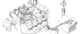
Design of NSh pumps
Due to the fact that the operating scheme of this type of device is very simple, they are popular in hydraulic drives of road cars. You can find many drawings where the principle of their operation is very clearly explained. The units can be used with either right or left rotation.
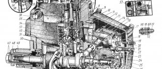
Diagram of a gear pump with external gearing.
Pump diagram
The numbers indicate the following details:
- Drive gear.
- Driven gear.
- Shaft connected to the drive.
- Shaft sealing system.
- Rear hub.
- Front hub.
The remaining types have some minor changes in the design.
Device
Gear pump design
A gear pump has the following device: it includes two gears and a housing inside which they are fixed. One of the gears is the drive gear and is driven by an external mechanical drive. The second is driven by the first due to gearing. Rotating, they move the liquid between the teeth from the suction chamber (1) to the discharge chamber (2).
Main characteristics and advantages of gear pump
Gear pumps are compact and simple with a minimum number of moving parts. They cannot produce high pressures like piston pumps, but have higher pressures and flow rates than centrifugal pumps. Gear pumps are especially suitable for pumping oils and other highly viscous liquids. The oil pump in a car engine has exactly this design and works without intervention for almost the entire service life of the car, but if you have problems with oil pressure, then you should not delay them, but rather immediately contact https://autorenovation.ru/. They will carry out all the necessary diagnostics and fix the problem with the car. External gear pumps can handle higher pressures (up to 200 bar) and flow rates due to stiffer shaft support and tighter tolerances. Internal gear pumps have better suction capabilities and are suitable for high viscosity liquids. Since capacity is directly proportional to rotational speed, gear pumps are commonly used for dosing and mixing applications. Gear pumps can be designed to handle aggressive fluids. Although they are typically made of cast iron or stainless steel, new alloys and composites enable pumps to handle corrosive fluids such as sulfuric acid, sodium hypochlorite, ferric chloride and sodium hydroxide. External gear pumps are used in heavy equipment to provide hydraulic power. By rotating the gear pump in the reverse direction using oil pumped from elsewhere, a hydraulic motor is created.
Principle of operation
Principle of operation
The gear pump has the following operating principle, which we will consider step by step:
- Liquid intake occurs due to the disengagement of gears in the suction chamber (1). The diverging teeth expand the volume of the suction chamber (1), as a result of which a vacuum is formed in the chamber, which is rapidly filled with liquid through the suction channel. Due to the pressure difference in the intake line and the supply chamber (1).
- Gears transfer working fluid in the space between the teeth, from chamber (1) to (2);
- When the teeth of the gear pump engage, the volume of the chamber decreases. As a result, liquid is squeezed out of the discharge chamber.
Types of gear pumps
There are several types of pumps. They can be classified according to the following criteria:
- the nature of the adhesion can be internal or external;
- the mechanism can be equipped with screw, chevron or straight teeth;
- can have right, reverse or left rotation;
- Depending on the number of interlocking rotors, a gear oil pump can be double-rotor or multi-rotor;
- they are divided into single-stage and multi-stage according to the number of stages;
- also the presence of regulation can be regulated or unregulated;
- Depending on their performance from the pressure supply, the pumps can be unloaded, unloaded, or have automatic adjustment of the end clearances.
Gear pump model
Due to the fact that the operation of this device can be qualified based on several characteristics, this characteristic is conditional.
Principle of operation
Although the whole mechanism has some differences, the operation of the gear pump still has a general scheme.
The driving and driven gears are located in the housing. When rotation occurs, all the air that previously filled the volume between the teeth immediately passes into the discharge line. It is located in the suction cavity. Here, due to this process, a pressure difference occurs, due to which the oil from the tank gets the opportunity to rise. On its way it fills the space between the teeth. When the gears rotate, the liquid enters the discharge cavity, and when the teeth engage, it is forcefully forced into the discharge pipeline.
When operating the mechanism, it is worth remembering that the entire process of rotation of the liquid occurs in a certain direction.
Advantages and disadvantages of gear pumps
Advantages of use:
- The simplest in design, resulting in the cheapest volumetric pumps;
- Very compact;
- High reliability;
- Minimum requirements for cleaning the working fluid;
- No lubrication is needed, its role is performed by the working fluid;
Disadvantages of work:
- Low efficiency, in most cases its value is no more than 0.6-0.75, this indicator is the smallest relative to other types;
- Pulsation of the working fluid in the discharge line, resulting in pressure surges, which produces relatively high noise (up to 90 dB). This is caused by the design features of the gearing.
- The load on the gear supports is high. Occurs due to the high pressure difference in the discharge and suction areas. Leads to an increased rate of wear of the supports, which reduces the service life of the device.
- Not recommended for use in high pressure hydraulic systems. In such systems, pumps are subject to increased wear and tear and quickly fail.
Varieties
There are 2 main types of gear pumps:
- External gear.
This is the most common type of unit. Its main feature is that the gears are installed opposite each other in the same plane. They are divided into the following 3 subtypes:
- Chevron.
- Cylindrical with oblique teeth.
- Cylindrical with straight teeth.
Chevron models are more modern, cylindrical models are outdated. In most cases, the body is made of cast iron, and the internal elements are made of stainless steel.
Pros:
- High outlet pressure.
- Pumping very viscous media.
- Overload-proof bearing mechanism on both shafts.
- A variety of materials ideal for different conditions.
- Minimum noise level.
The disadvantages are that liquid with solid inclusions is not allowed to pass through the pump.
- Internal gear.
Compared to the modification discussed above, models of this subtype are more compact - due to the slightly different structure of the working elements. It is also equipped with a pair of gears, but they are installed not in the lateral plane, but one in the other.
Source ytimg.com
The internal one is equipped with external teeth - it is the leading one. The outer one, on the contrary, has teeth facing inward. Therefore, the principle of operation of the gear pump of this modification is somewhat different - the pumped medium passes between the teeth of the outer and inner gears, which are in close contact during rotation.
The advantages are manifested in the ability to pump denser liquids, as well as the ability to adjust the gap between gears. Disadvantages - low performance, minimal corrosion resistance of the bearing due to its location in the pumped medium.
Check
⇐ PreviousPage 2 of 3Next ⇒4.3.1Technical condition of the pump
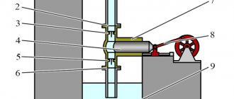
The KI-1097 device is connected to the pump discharge line as shown in the diagram (Figure 2, b) using fittings and hoses supplied with the device.
| Figure 1 KI-1097 device for diagnosing hydraulic system units 1-body, 2-sleeve, 3-plunger, 4-rod, 5-pointer, 6-pressure gauge, 7-throttle handle, 8-limb, 9-set screw |
Figure 2 Diagram of connecting the device to the tractor hydraulic system:
1 – pump, 2 – throttle-flow meter, 3 – tank, 4 – distributor.
The volumetric flow of the pump is determined at a rotation speed of the electric motor of the stand corresponding to the nominal speed of the engine crankshaft and an oil temperature in the tank of 50±5°C. Before turning on the electric motor, you must make sure that the device line is open. By turning the throttle handle, the pressure in the pump line is raised to 10 MPa and the volumetric flow is determined. If the volumetric flow of the pump does not meet the permissible limits given in table 1, then the pump must be replaced.
Table 1 Standard values of volumetric flow of the tractor hydraulic system pump
| Tractor brand | Pump brand | Pump volume flow, l/min |
| nominal | acceptable | |
| K-700 | NSh-46U | |
| K-700A | NSh-67L | |
| K-701 | NSh-76L | |
| T-150K | NSh-50L | |
| T-74, DT-75 | NSh-46 | |
| DT-75M | NSh-46U | |
| T-4A | NSh-46 | |
| MTZ, YuMZ | NSh-32 | |
| LTZ-155 | NSh-32U | |
| T-25A | NSh-10 | |
| T-700 | NSh-32 | |
| T-150, T-150K | NSh-50K |
4.3.2 Technical condition of the distributor
Connect the inlet fitting of the device to the distributor fitting (to the lifting cavity), and the drain fitting to the lowering cavity - “0” (Figure 2, a). Set the throttle handle to the “open” position, and the spool handle to the “lift” position. By turning the throttle handle clockwise, set the pressure on the device pressure gauge to 10 MPa and at the same time determine the oil consumption using the dial scale. If the volume flow of the pump after the distributor drops by more than 5 l/min, this indicates a malfunction of the distributor.
4.3.3 Spool return pressure
At medium engine speeds, set the throttle handle to the “open” position and the spool handle to the “lift” position. By turning the handle of the device and following the pressure gauge arrow, increase the pressure until the return mechanism operates. At the moment the machine is triggered, the pressure gauge needle drops sharply. The highest pressure noted on the pressure gauge is taken as the triggering pressure of the mechanism. For greater accuracy, the experiment is repeated 3-4 times and the average pressure is calculated.
Check the response pressure of other spool valves as follows:
1) set the spool handle, to the oil lines of which the device is connected, to the “lift” position;
2) set the handle of the spool being tested to the “raise” or “lower” position;
3) holding the first handle in the “lift” position with your hand, slowly increase the pressure in the discharge lines until the automatic valve of the spool being tested is activated. At the moment when the handle of the spool being tested slips out from under your hand, you need to notice the pressure on the pressure gauge.
The actuation pressure of automatic spool valves should be 10.0-11.5 MPa. If it is higher than 12.5 MPa or lower than 10 MPa, then it is necessary to adjust the booster spring of the return mechanism.
4.3.4 Safety valve response pressure
Set the spool handle to the “lift” position and, holding it in this position, use the throttle handle to smoothly close the oil drain from the device until the safety valve operates and determine the pressure using the pressure gauge reading.
The normal opening pressure of the safety valve should be in the range of 13.0-13.5 MPa. If it is higher than 14 MPa or lower than 12.5 MPa, then the valve must be adjusted.
4.3.5Hydraulic cylinder condition
The suitability of the power cylinder for further operation is determined by the amount of internal oil leakage. To do this, connect the device to the side section of the hydraulic system distributor (Figure 2, a) and set the throttle handle to the “open” position. Set the main cylinder spool lever to the “lift” position and make sure that it returns to the neutral position after lifting the linkage mechanism. Disconnect the shut-off device of the hose supplying oil to the cylinder lowering cavity, press out the valve ball and jam it in the open position. Let the oil drain and lower the hose into a measuring vessel. At nominal speeds, first set the spool lever, to which the KI-1097 device is connected, to the “lift” position, and then the power cylinder spool lever to the “lift” position. Holding both levers in this position, rotate the handle of the device to create a pressure of 10 MPa in the line and turn on the stopwatch. If no more than 10 cm3 of oil flows into the measuring vessel in 1 minute, then the power cylinder is fully operational.
To determine the stroke of the piston rod, secure the power cylinder fork in the frame, leaving the rod head loose. Connect the cylinder to the distributor with high pressure hoses. The cylinder cavities marked “P” and “O” are connected to the distributor cavities marked with the same letters.
Turn on the electric motor of the stand. Set the spool to the “lowering” position, bring the pressure to 11.5 MPa. Turn off the electric motor. Use a sharp pencil to mark the position of the rod.
Turn on the electric motor of the stand. Set the spool to the “lift” position and increase the pressure to 11.5 MPa. After the spool automatically returns to the neutral position, stop the stand electric motor. Measure the piston stroke with a ruler.
Attach the movable stop to the middle part of the rod. Turn on the electric motor and set the spool to the “lowering” position. Retract the rod until the movable stop presses on the shank of the hydromechanical valve, which should drop sharply and close the channel of the drain cavity line. In this case, the gap between the shank and the movable stop must be at least 3 mm. Throttle the oil pressure in the discharge cavity to 10 MPa. The hydromechanical valve must tightly close the cylinder drain channel and the rod must not retract. If the stem retracts, replace the valve body O-ring and front cover, replace the valve O-ring. If the hydromechanical valve does not work after replacing the sealing rings, send the power cylinder for repair.
4.3.6 Technical condition of the power steering
1) Start and warm up the engine of the MTZ-80 tractor. Set the nominal engine speed
2) Using the graduated disk, determine the free play of the steering wheel. If the backlash is more than 30°, the engagement of the worm and the sector, sector and rack should be adjusted by selecting the required number of shims
3) Determine the force applied to the steering wheel rim to turn the wheels from one extreme position to the other. If it exceeds 25N, then it is necessary to adjust the gaps in the indicated gears
4) Determine the time for turning the guide wheels from the driving position in a straight line to the extreme left or right position. If this time is more than 3 seconds, then it is necessary to remove the cap and adjust the constant flow valve
5) Check and, if necessary, adjust the safety valve. With proper adjustment, the oil should flow through the safety valve at a pressure of 8 MPa at any extreme position of the wheel
⇐ Previous2Next ⇒
Site search:
Description
A gear pump is classified as a type of volumetric rotary hydraulic machine. A gear pump is a rotary pump with a working body in the form of two gears.
When the gears rotate, fluid flows from the suction cavity into the cavities between the teeth and moves into the pressure cavity.
As a rule, gear pumps are used to supply petroleum products and other liquids without abrasive impurities. Despite the fact that the operating principle of all gear pumps is the same, they can have completely different structures, differ in details and operate under different conditions.
External gear pump
The electric motor rotates the shaft with the drive gear. The drive gear in turn rotates the driven gear.
Due to the minimal gap between the gears, as well as the gear teeth and the walls of the working cavity, a vacuum is formed when rotating in the suction zone.
However, where the gears mesh, so-called locked volumes . One of the technical problems in gear pumps is the problem of blocked volumes , which is an undesirable phenomenon.
Due to the low compressibility of the liquid, the occurrence of blocked volumes during pump operation, if measures to combat them are not taken, can lead to the occurrence of a large moment of resistance.
Pump manufacturers take this problem seriously and combat it with various methods. For example, a fluid drainage channel is drilled between the gear teeth, through which the fluid flows back into the suction cavity.
A system for maintaining pressure in the discharge pipeline is also installed.
When the pressure in the discharge pipeline drops, the number of gear revolutions increases. When increasing, on the contrary, it decreases.
There are also pumps that are capable of passing rather large impurities along with the liquid.
Main and characteristic causes of failure of NSh gear pumps
Recommendation: to operate NSh hydraulic pumps without breakdowns, the operating hours should not exceed:
- 4000 operating hours on agricultural tractors.
- 3000 operating hours on industrial tractors.
- 1000 operating hours on other machines.
Possible causes of malfunctions of NS pumps:
The pump does not pump hydraulic oil into the hydraulic system or pumps in insufficient quantities and does not create pressure.
- The pump drive is faulty.
- The setting pressure of the distributor safety valve is less than the operating pressure of the hydraulic system.
- Presence of oil leaks.
- Low oil temperature.
- Mismatch between the directions of rotation of the pump and drive.
- Increased pump wear due to contamination of the hydraulic system oil.
Foaming in the hydraulic tank. The pump captures and forces air into the hydraulic system.
- violation of the tightness of the suction pipeline.
- low oil temperature.
- wear of the cuff of the pump drive shaft.
Vibration, noise during operation of the NS pump, as a result, rapid wear of the pump bearings and its failure. Presence of air in the hydraulic system.
- pipelines or hydraulic system components are not secured.
- The shut-off elements of the safety valves vibrate.
- wear of the pump drive coupling.
- cavitation in the pump (the suction hole is blocked, pipelines are narrowed or bent, excessive oil viscosity or low temperature).
The gear pump does not develop maximum pressure.
- The spool of the hydraulic distributor safety valve is clogged.
- the adjustment of the hydraulic distributor safety valve has been disrupted.
- The hydraulic valve spool sticks (does not move).
- wear of pump parts.
Overheating of the hydraulic pump during operation.
- presence of mechanical impurities in the oil, presence of air in the hydraulic system, insufficient oil level in the hydraulic tank.
- long-term operation of the hydraulic system at maximum loads (the safety valve is stuck or its settings are disrupted).
- The hydraulic system filter is clogged.
- increased vacuum in the drain hydraulic line (crumpled, narrowed pipelines).
- jamming of pump parts due to wear.
Oil leakage along the drive shaft of the NSh pump into the crankcase.
- The shaft seal collar is worn out or squeezed out if the directions of rotation of the pump and drive do not match.
Spontaneous shutdown of the NS pump.
- Malfunction of the gear pump drive mechanism - the clamp spring has weakened.
Destruction of the NSh pump housing - cracks, holes.
- The hydraulic distributor safety valve is incorrectly adjusted.
- The spool of the hydraulic distributor overflow valve is stuck.
Taken from www.ladspb.ru
Marking
When choosing a gear pump, knowledge of the decoding of the information indicated in the labeling will be useful. The first row contains the letters:
- NS – gear pump.
- M - for pumping oil.
- F – flange mounting.
Then follow the numbers:
- The volume of the pumped medium in liters with a gear stroke of 100 revolutions.
- Maximum pressure kg/cm².
- Delivery per hour.
- Outlet pressure.
The following indicates the type of material of the internal elements:
- Yu – duralumin alloys.
- K – stainless steel.
- B – bronze.
- Without a letter - cast iron.
The direction of rotation of the drive shaft is designated - L - left, R - right.
Video about how an external gear pump works:
Flaws
However, such pumps have disadvantages :
- unregulated working volume;
- inability to work under high pressures; or:
- high demands on materials for manufacturing wear parts.
- high demands on the quality of manufacturing of gears and plates forming the housing;
- double changes in the direction of fluid movement in the pump reduces efficiency.
By the way, read this article too: How a sucker rod pump works
Gear pumps are widely used in the field of pumping high-viscosity liquids with temperatures up to 250°, for example, liquids such as edible oils, fats, chocolate mass, varnishes, paints, petroleum products, household chemicals, etc.