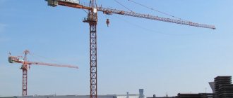
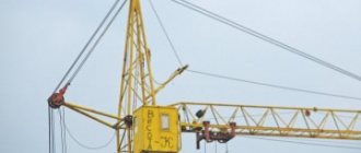
Tower crane KB-403
Before studying the technical characteristics of KB 403, you need to familiarize yourself with this model in more detail. It is a mobile structure placed on a special move, equipped with a rotating turret, as well as a beam-type boom mechanism. Due to its features, the crane is widely used in the construction industry in the construction of residential buildings, industrial and other structures whose height does not exceed 16 floors. It can be used for moving and installing individual structural elements, the weight of which can reach 8 tons.
The crane was produced by domestic enterprises - Nezepetrovsky, as well as the Moscow plant. Its model range includes 3 main modifications - standard, “A” and “B”. They differ significantly in their performance indicators, which made it possible to expand the scope of application of this device. Modification “A” is distinguished by increased speed of lifting and moving loads, as well as high-quality thermal insulation of the cabin. The “B” version is distinguished by the possibility of erecting structures whose height reaches 17 floors.
Crane KB-403
The crane can be moved to the work site either assembled or disassembled. In this case, in the first case, rolling trolleys are used, and in the second, freight transport is used over several trips.
Crane design
The excellent performance characteristics that distinguish the KB 403 tower crane are due to its simple, well-thought-out design. If we look at it in more detail, we can highlight several key nodes:
- platform equipped with a mechanism;
- frame;
- a tower consisting of several sections;
- operator cabin;
- boom and related elements.
Be sure to read: Technical characteristics of the KS 55713 crane and its modifications
Due to the high quality of manufacturing materials, as well as the high reliability of key elements, this crane can be operated at temperatures from -40 to +40 degrees. When studying the structure of the product, it is necessary to note several important features that distinguish this domestic unit from a number of analogues.
The cargo trolley is secured with hinges and cables, which allows you to move loads in the vertical and horizontal directions. The model provides the possibility of installing a security system, which makes working with it more convenient. The crane can be controlled either directly from the cabin or from the ground.
The disadvantages of the KB-403 crane include the relatively low quality of cabin insulation , which makes it difficult to work in it during the cold season. It can be compensated by installing an additional heating system, which will maintain a comfortable temperature.
Scope of application
Cranes of the KB-403 type are particularly popular and the most widely used among other special lifting machines. They are used on large construction sites and facilities that require large volumes of construction or installation work, speed and high productivity:
- In the construction of residential or administrative buildings.
- On the construction of large industrial complexes.
INTERESTING! KB-403 is capable of performing absolutely all work on lifting any cargo on site, which allows significant savings on the use of additional lifting equipment.
Technical characteristics of KB-403
As mentioned earlier, it is the performance of this crane that has made it incredibly popular in the construction industry. Its actual technical characteristics depend on the specific modification, and therefore it is advisable to familiarize yourself with the parameters relevant for the standard version:
- electric motor/mechanism power - 116/5 kW;
- unit height - 37.9 m;
- lifting capacity/with the boom extended - 8/3 tons;
- maximum rise - 54.7 m;
- structure weight - 50 m;
- boom radius - 30 m;
- moving speed—18 m/min;
- number of sections - up to 5 pcs.
Scheme KB -403
The track of the unit is 6 m, and a special drive allows it to move on uneven surfaces without any problems, which makes it indispensable when working on a construction site.
Modifications
At the moment, there are several modifications of the basic model of the KB-403 tower crane, these are:
- The KB-403A crane, which is distinguished by lifting up to the 16th floor, more convenient and easier control from a structurally improved cabin, increased lifting speeds and movement of the loading trolley, as well as greater stability with an increased load moment.
- KB-403B, designed for lifting loads on buildings up to 17 floors. It has a larger boom radius and is available in 4 variants with different load torque (from 120 to 132), total height, boom radius, etc. It is distinguished by its reliable design and ease of maintenance.
- KB-403B.4 is used in lifting loads up to 35.4 m. It has an increased boom reach and load moment.
Comparative characteristics of the models:
| Options | KB-403A | KB-403B | KB-403B.4 |
| Structural weight, t | 50 | 50,5 | 46,6 |
| Total weight, t | 80 | 80,5 | |
| Track, m | 6 | 6 | |
| Load moment, t*m | 132 | 120 | 132 |
| Maximum load capacity, t | 8 | 8 | 8 |
| Load lifting at full boom reach, t | 4,5 | 3 | 3 |
| Maximum boom radius, m | 25 | 30 | 30 |
| Boom radius with max. load, m | 16,5 | 15 | 16,5 |
| Lifting height at full reach, m 41 | 41 | 41 | 24,2 |
| Maximum lift, m | 52 | 54,7 | 37,9 |
| Landing speed, m/min | 4,8 | 5 | 5 |
| Lifting speed max. load, m/min | 40 | 40 | 40 |
| Maximum lifting speed, m/min | 58 | 55 | 55 |
| The highest speed of the chassis | 18 | 18 | 18 |
| Speed of movement of a filled cart | 23 | 30 | 30 |
| Rotation speed, rpm | 0,6 | 0,65 | 0,65 |
| Possible degree of wind gust | IV | III | VII |
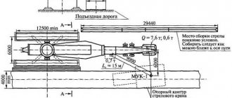
Installation and dismantling of KB-403
In most cases, the crane is moved to the work site in disassembled form using vehicles, and therefore there is a need for its installation. This process is extremely simple and allows you to prepare the unit for full operation in a short time. In order for it to complete successfully, you need to adhere to the simplest algorithm of actions:
- Install and level crane tracks.
- Mount the chassis using a medium-duty crane.
- Place the tower vertically.
- Hang the boom using the hinges.
- Pull out the tower, configure all the necessary components.
Be sure to read: Truck crane Ivanovets
All structural elements are made of corrosion-resistant materials, which allows the device to be installed and used in any weather conditions.
To lower the load at low speed, a reduction clutch is installed on the cargo winch, controlled by a brake with an electromagnet YB2 using the SB1 button. When the button is turned on, relay KM 11 is turned on and the power supply circuit of the electromagnet YB2 is opened. The brake is closed, the planetary mechanism of the reduction clutch is activated, and the cargo winch begins to operate at a reduced speed.
In the turning mechanism, smooth starting and braking is ensured by a flywheel mounted on the high-speed gearbox shaft.
Crane KB-271. The electrical equipment of the crane (Fig. 109,110) is designed to be powered from an external three-phase AC electrical network with a line voltage of 380 V via a neutral wire. The control circuit operates on alternating current with a voltage of 380 V and direct current received from the VD2 rectifier, the working lighting circuit operates on alternating current with a voltage of 220 V, and the repair lighting circuit operates on alternating current with a voltage of 12 V from a step-down transformer.
Rice. 109. Electrical diagram of the control circuit of the KB-271 crane
Rice. 110. Electrical diagram of the power circuit and the lighting, alarm and electrical heating circuit of the KB-271 crane
The motors are powered through the input switch Q1, the circuit breaker QF1, the contacts of the KMO linear contactor and the contacts of the reverse contactors.
Motors with a squirrel-cage rotor are used to drive the boom winch and the movement mechanism. The drive of the turning mechanism uses a motor with a wound rotor. To obtain low ascent and descent speeds, an asynchronous AC brake machine and dynamic braking of the drive motor with a wound rotor are used in the cargo winch drive.
Rice. 111. Electrical diagram of the power circuit of the KBR-1 crane
The electric motor M4 of the turning mechanism is controlled by the command controller S2.
In the 1st position (to the right or to the left), the motor stator is connected to the network, the KM15 contactor is turned on and put on self-power, which turns on the brake electromagnets YB3, YB4. The drive is released and the motor begins to operate with total resistance introduced into two phases of the rotor circuit.
In the 2nd position, the KM12 contactor is turned on, short-circuiting part of the resistance of the rheostat R2 and opening the circuit of the KT4 time relay coil with its block contact. The relay disappears with a time delay and prepares the KM13 contactor to turn on.
In the 3rd position of the controller, if the KT4 relay has already dropped, the KM 13 contactor turns on, short-circuiting almost the entire resistance of the rheostat R2. The engine operates at a characteristic close to natural, and the turning speed will be the highest.
When the controller handle is returned to the zero position, the motor stator is disconnected from the network. Contactors KM12, KM13 are also switched off and introduce the full resistance of the rheostat R2 into the rotor circuit. Since the contactor KM15 remains switched on, the brakes YB3 and YB4 will be released and the turning mechanism will freely run out. To slow down the mechanism, you need to press (to the right) the SQ4 pedal, which with its contact will close the circuit of the KM14 contactor coil. The M4 engine will begin to operate in dynamic braking mode, slowing down the turning mechanism.
To completely stop the mechanism, press the SQ4 pedal a second time (to the left). In this case, the opening contact of the pedal will turn off the KM15 contactor. Brakes YB3 and YB4 will be disconnected from the network and the drive will brake.
The electric motors M2 and M3 of the movement mechanism are controlled by the command controller S3.
In the 1st position “Forward”, the contactor KM16 is turned on, which supplies power to the motors M2, MZ and brake electromagnets YB1 and YB2. The movement mechanism is released and begins to operate at a reduced speed, since the stators of the motors M2, MZ are connected to the network in series with resistances RI and the motors develop a torque less than the nominal one.
In the 2nd position of the controller, contactors KM18, KM19 are turned on, which bypass the rheostat Rl. At the same time, the motors develop a nominal torque, ensuring the operating speed of the crane. In the “Backward” direction the drive operates similarly.
The electrical circuit provides the ability to control the crane mechanisms during testing from a remote control panel, on which an emergency switch S5 and buttons SB2 ... SB11 are installed. Switching control to the cabin or to the remote control panel is done by moving the S7 switch handle to the “k” position (control from the cabin) or to the “sh” position (control from the remote control panel).
Protection of electrical equipment and crane mechanisms is carried out using protective relays, circuit breakers, fuses and limit switches.
Zero protection is achieved using the contacts of the S1 controllers. 1, S2.1, control circuits of the KBR-1 crane, S3.1, S4.1, handles closed only in the zero position. These contacts are connected in series with the SB1 button in the coil circuit of the KM 10 linear contactor.
The motors of the boom winch and the movement mechanism are protected from overload by thermal relays KK1 and KK2, the contacts of which are included in the KMO coil circuit. The crane rotation and load lifting motors are protected from current overload using block maximum current relays KF1, KF2. The common relay contact is connected to the KMO coil circuit.
One phase of the brake machine MB and the power circuit of the VD1 driver is also protected by the KF2 relay, and the other two phases are protected by a three-pole QF2 circuit breaker. The third pole of the machine is connected to the KMO coil circuit, so when the machine is triggered, the line contactor is turned off.
Protection of the common supply circuit from short circuit is carried out by the QF1 circuit breaker and the fuses of the input box Q1,
End protection against movement of extreme positions by the valve mechanisms is carried out using operating position limiters.
The limit switch SQI of the lift height limiter is connected to the coil circuit of the KMO linear contactor. Limit switches SQ3.I, SQ3.2 of the extreme positions of the rotation mechanism, SQ5.1, SQ5.2 of the extreme positions of the travel mechanism, SQ6, SQ7 of the extreme positions of the boom are connected in series with the corresponding coils of the reverse contactors of the electric motors of the mechanisms.
In the lighting, heating and alarm circuit, lamp EL1 for illuminating the control cabin and lamps EL2, EL3, EL4 for illuminating the crane operating area are controlled by package switches SA1, SA2. The control cabin is heated by an EY heating device. and tubular heaters EK2, EKZ are used to heat the glass of the cockpit canopy.
The NL1 sound siren is activated by the SB11 button and the closing contact of the output relay of the M-95M-2 anemometer. When the wind load is acceptable, the relay contact in the siren circuit will be open. When the anemometer output relay is turned on due to increased wind, the relay contact will close and turn on the siren.
For repair work in the dark, the crane is equipped with a T2 transformer with an output voltage of 12 V and XSI sockets.
Lighting, heating and alarm circuits are protected by fuses. The connection of these circuits to the power circuit of the crane is carried out in the area between the input box Q1 and the QF1 machine.
Crane KBR-1. For the KBR-1 crane, the electrical circuits (Fig. 111, 112) for driving the mechanisms for moving the crane along the rail track and turning are made in the same way as for the KB-271 crane. The cargo winch uses a dual-motor AC drive, consisting of a main MB motor with a wound rotor and an auxiliary two-speed MS motor with a squirrel-cage rotor.
To drive the cargo trolley, a two-speed Ml motor with a squirrel-cage rotor is used, controlled by a command controller S4. In the 1st position, forward or backward, the KM25 contactor turns on the low-speed stator winding of the Ml motor (8 pairs of poles) and the cargo trolley moves at a speed of 8.3 m/min. When the command controller handle is moved to the 2nd position, the KM25 contactor is turned off and the KM26 contactor is turned on, which connects the high-speed stator winding (three pairs of poles) to the network. The speed of movement of the cargo trolley increases to 25 m/min.
The electrical circuit of the crane provides the ability to control all mechanisms from a remote control panel. The remote control is intended only for work related to testing the crane. Using the remote control to carry out loading and unloading or construction and installation work with a crane is strictly prohibited, since when controlling mechanisms from the remote control, the operation of the current protection of the electric motors and the operation of the load capacity and lifting height limiters of the hook suspension will not cause the linear contactor to turn off. The control location is selected by setting the switch to the “k” position (for control from the cab) or to the “l” position (for control from the remote control).
The WE signal lamps in the control cabin and HL2 on the remote control panel light up when the KMO linear contactor is turned on.
The same electrical circuit with some minor changes is used on the KB-403A crane.
Crane KB-308. The electrical circuit of the KB-308 crane (Fig. 113, - a, 6 and 114) differs from the circuit of the KBR-1 crane mainly in the drive of the cargo winch. The KB-308 crane also uses a twin-engine drive, but (unlike the one discussed in § 44) in this drive, low landing speeds for lowering the load are achieved by switching the main engine into dynamic braking mode with self-excitation. In this case, the motor is disconnected from the network, and its rotor is connected to two phases of the stator through a three-phase rectifier.
The engine rotates under the action of a load, and the rectified emf. provides a dynamic braking current in the stator, the magnitude of which depends on the mass of the lowered load. Moreover, the lowering speed does not depend on the gravity of the load, but is determined by the rotor resistance connected in series with the rectifier.
For stable operation of the motor in dynamic braking mode, the circuit provides for initial stator magnetization from the external network through a half-wave rectifier with a shunt diode. The bias current is limited by the additional resistance R4 and is controlled by the current relay KA1.
The drive provides increased speeds when lifting and lowering loads, not exceeding half of the nominal ones. Let's consider the operation of the drive circuit. In the zero position of the command controller, the contactor KM7 and relays KM6, KT2, KTZ, KT4 are turned on. The mechanism is inhibited because the KM12 contactor is disabled.
In the 1st lifting position, contactors KM2, KM1, KM12, KMZ, KT1 are switched on. Relay KT4 is turned off. The motor Ml is turned on with full resistance in the rotor circuit and the motor M2 is turned on at low speed. The drive operates at characteristic 7/7 (Fig. 113.6).
In the 2nd lifting position, the KM10 contactor is turned on, short-circuiting part of the resistance Rl and turning off the KMZ contactor. The M2 engine is switched off. The drive operates at 2P characteristic.
In the 3rd lifting position, contactors KM2, KM12, KMYu, KM7, KM1, KM6 and relays KT1, KT4, KTZ, KT2 are turned on.
Rice. 114. Electrical diagram of the control circuit of the cargo winch drive of the KB-308 crane
The Ml engine, through the intermediate characteristics ZP and ZbP, switches to the ZP characteristic, operating with a small non-inputable resistance in the rotor circuit.
In the 4th lifting position, the KM13 contactor is switched on and is set to self-power with its block contact. The KM 13 contactor can only be switched on when the contact of the load speed limiter SQ2 is closed. Contactors KM2, KM!, KM9, KM8, KM7, KM6 are switched off. Ml engine is disabled.
Motor M2 is switched on to the high-speed winding. The drive operates at 4P characteristic.
In the 1st position of descent, contactors KM11, KM12 and relays KA1 and KT1 are turned on. Motor Ml is released and rotates under the influence of the load. The resistance in the motor rotor circuit Ml is minimal, since the KM7 contactor is turned on. The drive operates at characteristic 1C.
In the 2nd descent position, in addition to the relays already switched on by the contactors, the KM5 contactor is switched on, connecting the low-speed winding of the M2 motor to the network. The drive switches to characteristic 2C.
In the 3rd descent position, the KMZ contactors are turned off. KM7, KM6. A full rotor resistance is introduced into the rotor circuit, and the drive switches to the ZS characteristic.
In the 4th descent position, the KM10 contactor is turned on, bypassing the rheostatic resistance stage and the VD1 rectifier. Contactors KM1, KM4 are turned on, and under the control of a time relay, acceleration contactors KM7, KM8, Sh9 are turned on. In the motor rotor circuit Ml, only a non-removable resistance stage remains. The drive operates at a 4 C characteristic.
In the 5th descent position, the KM14 contactor is turned on and put on self-power. Contactors KM4, KM9, KM8, KM7 are switched off. Motor Ml will be turned off and motor M2 will be turned on at high speed. The drive operates at characteristic 5C, providing lowering of light loads (up to 0.5 rated load) at increased speed.