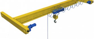
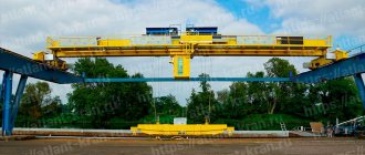
The kinematic diagram of an overhead crane allows you to understand the operating principles of all crane units and mechanisms. In general, the operating principle of all lifting and transport equipment is the same: the base is one or two metal beams on which a cargo winch is placed, driven by an electric motor.
The type of crane equipment depends on the type of structure and the specifics of the loads being lifted. However, it is worth noting that the main components of lifting mechanisms are similar.
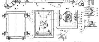
General kinematic diagram of an overhead crane
Rice. 1. Kinematic diagram of the overhead crane movement mechanism
Figure 1 shows a typical kinematic diagram of a crane mechanism, including:
- Electric motor (asynchronous three-phase motors are most often used).
- Brake – provides stopping and fixing of the moving load in any position.
- Gearbox – reduces the engine speed.
- Drum – serves for uniform tension of crane cables.
- A pulley block is a single one or a clip of several blocks that ensures efficient distribution of energy from the drive and gains in speed and strength.
- Hook – a device for grabbing a load.
Additional devices and safety devices
Overhead cranes operating outdoors are equipped with anemometers that measure wind force and signal the need to stop loading operations if the wind force exceeds the permissible level. In addition, cranes on open trestles can be equipped with anti-theft grips. Such grips, made in the form of pliers or blocking the running wheels of stops, will prevent the movement of an idle crane or its trolley under the influence of strong wind pressure.
All overhead cranes must be equipped with an audible alarm (electric bells or sirens). With its help, workers in the workshop are notified of the increased danger that arises during crane operation.
Light and sound alarms in the crane operator's cabin serve to inform about possible malfunctions of the crane or dangerous areas (approaching the end stops or an adjacent crane). The main trolleys of the crane are equipped with a light alarm (red lamps) indicating the presence of voltage on them.
Kinematic diagram of the traveling mechanism of an overhead crane
Rice. 2. Transmission diagram of a crane with individual drive
The crane movement mechanism can be central or individual. In turn, the central movement is divided into two types: with a high-speed and low-speed transmission shaft.
Rice. 3. Kinematic diagram of the movement of an overhead crane with a low-speed transmission
The crane drive with a low-speed transmission is installed in the middle of the bridge and includes: engine 3, brake clutches 2 and gearbox 1. The output shaft of the gearbox is connected to the transmission shaft 4, made of prefabricated sections that are connected by couplings 5 installed in bearings. The couplings also connect the transmission shaft to the drive of the running wheels 7 using a gear 6. The shaft 4 rotates at the same speed as the wheels, transmitting maximum torque.
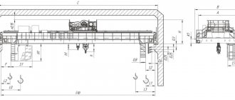
Kinematic diagram of the overhead crane lifting mechanism
In bridge-type crane structures, the lifting mechanism is placed on a load trolley. The number of lifting devices depends on the maximum weight of the load that the machine can lift.
The lifting scheme of lifting and transport equipment depends on a number of factors: the type of gripping device, the height and weight of the load being lifted, and the length of the span. When using a hook, grab or electromagnet, one lifting mechanism is used.
Rice. 4. Kinematic diagram of lifting an overhead crane with a hook
Designations in the figure:
- Engine
- coupling
- Brake
- Gearbox
- Drum
- Pulley hoist
- Fixed pulley block
For lifting in cranes, normal and shortened hook hangers are used.
This mechanism consists of a cargo rope running from the drum and bending around the hook suspension blocks, bypass blocks and equalizing block, a gearbox equipped with a brake, an intermediate high-speed shaft and a drive electric motor. To gain traction in lifting mechanisms, a chain hoist is used, which is a system of movable (in a hook suspension) and fixed (bypass) blocks. Lifting mechanisms for cranes with a lifting capacity of 80...320 tons are carried out according to the same scheme, they differ only in the presence of an additional reduction gear or a second gearbox, with the help of which the output shaft of the main gearbox is connected to the drum. In this case, the second gearbox performs the function of high-speed transmission. The additional gear wheel is rigidly connected to the drum, and the gear is mounted on a separate shaft on supports and connected to the output shaft of the main gearbox using a gear coupling or mounted on the output shaft of the gearbox. To reduce the cantilever load acting on the gearbox shaft, an additional support-bracket is used, which is attached to the gearbox housing. Rice. 20. Diagram of a lifting mechanism driven by an electric motor
Since the load from the gravity of the load is distributed between the branches of the hoisting rope, the lifting force can be less than the force of gravity of the load Q. However, to gain in force when lifting the load onto the drum, it is necessary to wind a greater length of rope than the path of the load. In the lifting mechanisms of overhead cranes, the most widely used are double multiple hoists, which allow only vertical movement of the load when lifting and lowering it, uniformly loading the drum supports and the span of the bridge. When using double chain hoists, two rope branches are simultaneously wound onto the drum.
Rice. 21. Scheme of double chain hoists with the following multiplicity
The multiplicity n of a double chain hoist is understood as the ratio of the number of rope branches on which the hook is attached to the number of rope branches running onto the drum. In the lifting mechanisms of cranes with a lifting capacity of 5...320 tons, double pulleys are used: with even multiples of 2, 4, 6 and 8 and odd multiples of 3 and 5. In the double pulley shown in Fig. 20, the number of branches on which the load is attached, and the number of ropes running onto the drum, therefore the multiplicity of the pulley is n-4. In Fig. Figure 21 shows diagrams of double pulley hoists n = 2, 3, 4 and 5. In double pulley hoists, equalizing blocks or equalizing balancers are used to level the length of the ropes due to uneven pulling (Fig. 21).
When using equalizing blocks, the pulley suspension rope consists of one part, the ends of which are fixed to the drum, and when using balancers, it consists of two equal parts, the length of which corresponds to the total length of the rope.
Due to the symmetrical suspension, the equalizing flea (or balancer) rotates at a small angle when pulling a new rope, compensating for the uneven tension of the rope branches in each pulley, and after running in the rope practically does not rotate. In double chain hoists of even multiplicity, equalizing blocks (or balancers) are placed in bearings on a fixed axis mounted on the trolley, and in chain hoists of odd multiplicity - on the movable axis of the hook suspension.
To increase the lifting height, as well as ease of inspection, the upper bypass and equalizer blocks, as well as balancers, should be installed above the level of the trolley frame deck.
The lifting mechanisms of overhead cranes use normal and shortened hook hangers to connect the load hook to the lifting rope.
In a normal hook suspension (Fig. 22, a), the hook, through a nut on the shank, rests on a thrust bearing, which transmits force from the hook to the traverse through a spherical washer. The traverse is hinged in the earrings and protective shields. An axis with blocks is fixedly installed in the upper part of the shields and earrings. The blocks can rotate in bearings. A sheet bracket is installed between the shields to prevent a rope block that is weakened when mooring a load from falling out of the stream. Depending on the diameter of the block, the gap between the bracket and the block is 0.15-0.3 of the rope diameter. If the multiplicity of the pulley is odd, an equalizing block is installed on the axis between the blocks. The nut is locked with a bar that fits into the slot of the hook. Washers and rings prevent lubricant from leaking out of the bearing cavity.
Rice. 22. Hook pendants: a - normal; 6 shortened
In a shortened suspension (Fig. 22.6), the hook and blocks are placed on a common traverse. Shortened hangers for cranes of small and medium lifting capacity are made with elongated single-horned hooks, and for cranes of large lifting capacity - with plate-shaped double-horned hooks (GOST 6619-75), hingedly connected by means of a fork to the traverse.
Drums made of cast iron and steel can be made cast (Fig. 23, a, b), welded-cast (Fig. 23, c) and welded-rolled (Fig. 23, d).
In the lifting mechanisms of overhead cranes for general and special purposes, cylindrical double drums with single-layer rope winding are used for double pulley hoists.
A double drum (see Fig. 23, c) consists of a shell with grooves cut on both sides along a helical line in the right and left directions for winding the rope. The right and left cuts are separated from each other by a smooth part. The ends of the rope on the drum are secured with pads 9. In welded-rolled drums, the grooves on the shell are made with a special roller (Fig. 23, d), or they are used as a profiled grooved tape, which is fixed by welding on a smooth shell.
Making grooves spaced at intervals of at least 1.1 times the diameter of the rope creates a larger contact surface between the drum and the rope, which helps reduce contact pressure and wear of the rope. The profile of the helical groove depends on the diameter of the rope being wound, so replacing a rope with another of a different diameter is unacceptable. The drums of the lifting mechanisms of grab and special cranes, during the operation of which jerks and weakening of the ropes are possible, are made with grooves with a depth of at least 0.5 of the diameter of the rope and are equipped with a device that ensures correct laying of the rope on the drum (clause 121 of the Rules).
The drum hubs are mounted on solid axles (Fig. 23, a, b) or separate axles (Fig. 23, a, d), supported by spherical rolling bearings, which make it possible to compensate for inaccuracies in the manufacture and installation of the drum. In the lifting mechanisms of low- and medium-lift cranes (Fig. 23, c), one of the bearings is located in the output shaft of the gearbox, and the other in a support mounted on the trolley. In heavy-duty cranes (Fig. 23, b), both bearings are installed in supports on the trolley frame.
Torque is transmitted to the drum in lifting mechanisms of low and medium load capacity through a built-in gear coupling (Fig. 23, c), the driving half-coupling (gear ring) of which is made on the output shaft of the gearbox, and the driven half is a drum hub with internal teeth connected to the shell drum; in heavy-duty lifting mechanisms (Fig. 23, b) the wall of the gear wheel is an open gear, which transmits torque to the drum through pressed bushings and is connected to the drum flange with bolts.
Rice. 23. Drums of the lifting mechanism: a - cast with a gear coupling; b - cast with a toothed rim; c - welded-cast; g welded-rolled
Each rope end on the drum is secured with at least two linings, the main dimensions of which are given in Table. 25. The length of the drum is calculated in such a way that when the load-handling device is completely lowered, at least 1.5 turns of rope remain on the drum, excluding the turns located under the clamping device (clause 120 of the Rules). These spare turns are called unloading turns; they reduce the tension of the rope at the attachment point by 2.5-4.5 times compared to the maximum. Options for fastening the linings with studs or bolts are shown in Fig. 24.
In lifting mechanisms for cranes of small and medium lifting capacity, horizontal gearboxes Ts2 are usually used (Tables 25-29), which have a load capacity 3-4 times greater than the previously used RM gearboxes. The output shaft of the Ts2 gearboxes can be made with a ring gear for connecting the lifting mechanism drum.
In the main lifting mechanisms of heavy-duty cranes, horizontal crane gearboxes are used (Tables 30-31), which have an external support bearing for the gear shaft connected to the drum ring gear.
In Fig. Figure 25 shows a general view of the arrangement of the main and auxiliary lifting mechanisms on the trolley of a general-purpose overhead crane with a lifting capacity of 20/5 tons. The main lifting mechanism uses a fourfold double pulley block, and the auxiliary one uses a double double pulley. The main lift mechanism is equipped with four bypass blocks and an equalizing block; the auxiliary lift mechanism is made without bypass blocks and has an equalizing block. The hook suspensions of the main and auxiliary lifts are shortened. The main and auxiliary lift drums are mounted on supports on one side, and rest on the output shafts of the gearboxes on the other side. Each drum is equipped with a spindle hook lift height limiter. The drive of the main and auxiliary lifts is carried out respectively by electric motors through high-speed shafts and gearboxes. Brake pulleys for brakes are installed on the output shafts of the gearboxes. To move the cart, a movement mechanism is used, the design of which is discussed in the paragraph.
In magnetic cranes equipped with a load electromagnet, the lifting mechanism (see Fig. 16) is additionally equipped with a special cable drum and a current collector for a flexible cable that supplies electricity to the load electromagnet. The cable drum is installed in supports near the drum of the lifting mechanism, from which it is driven through a gear or chain transmission. Moreover, the transmission ratio is selected such that synchronous movement of the electromagnet and cable is ensured during operation of the lifting mechanism.
Rice. 24. Fastening the rope to the drum: o - on the smooth part; b - on the recessed smooth part; c - on the sliced part
For grab cranes, lifting mechanisms are used, which are grab winches. The grab winch has two drums for the lifting and closing ropes of the grab. Moreover, to control the opening, scooping and lifting of the grab, it is necessary that each drum has an independent drive. For example, when lifting or lowering a grab, both drums must rotate synchronously; when opening a hanging grab, the hoisting rope drum is fixed, and the closing rope drum rotates in the direction of descent; When scooping, the lifting rope is weakened and the lifting drum is stationary, while the closing rope drum rotates in the lifting direction.
Grab winches are divided into single-drive and two-drive. A single-drive grab winch (Fig. 26, a) consists of a motor connected through gears on the shaft to a closing rope drum. The hoisting rope drum can be rigidly connected to the drum through a friction clutch and gears and with the help of a controlled clutch. This design of the grab winch allows the grab to be opened with the brake closed, the drum stationary and the drum rotating towards the descent. The subsequent raising or lowering of the open grab is carried out with the brake open and the clutch engaged. When scooping, the brake is closed, the drum is motionless, the clutch is open, and the clutch slips when the closing rope drum rotates. After the scooping process is completed, the brake is released, the clutch is engaged and the drum rotates synchronously with the closing rope drum. A significant disadvantage of single-drive winches is the impossibility of combining the opposite rotation of the drums to ensure accelerated opening or closing of the grab, wear of coupling couplings and clutches.
Double-price grab winches (Fig. 26.6) do not have the disadvantages of single-engine winches and are widely used in grab cranes. These winches consist of two crane single-drum winches, one of which serves for the lifting rope and the other for the closing rope. The crane single-drum winch is similar in design to the lifting mechanism in Fig. 20 and has its own drive. This allows for the combination of operations due to the independent activation of each winch and increases the productivity of the crane.
For overhead cranes intended for installation work, when special precision and care are required when lowering a load, multi-speed lifting mechanisms are used. In Fig. Figure 27 shows a diagram of a two-speed lifting mechanism, which consists of a conventional lifting mechanism (see Fig. 20), including a drum, gearbox, brake, drive electric motor, as well as a microdrive for the setting [(low) speed of lowering the load. The microdrive is connected to the shaft of the main electric motor and consists of an auxiliary electric motor, a brake, a gearbox and a planetary clutch and brake.
When the hoisting mechanism is running at main speed, the auxiliary motor brake is closed and the brakes are open. The torque of the main electric motor is transmitted through the gearbox to the drum of the lifting mechanism. When moving to low lifting or lowering speed, the brake is released, the auxiliary motor is switched on, and the motor is switched off. The torque from the auxiliary motor shaft through the gearbox, planetary clutch, main motor shaft and gearbox is transmitted to the drum, providing a low rotation speed.
Rice. 25. Placement of main and auxiliary lifting mechanisms on the trolley of a general-purpose crane with a lifting capacity of 20/5 t
The use of a planetary clutch when the rim is locked allows the main engine to rotate and lift or lower the load at main speed, and when the rim is free, it transmits rotation from the auxiliary electric motor and operates the lifting mechanism at low speed. To reduce excessive rotation speed of the auxiliary electric motor when the brake fails and when the main electric motor is running, use a centrifugal switch mounted on the motor shaft. To reduce the rotation speed of the main electric motor from excessive rotation in the event of a planetary clutch failure or brake malfunction, a centrifugal switch is used on the gearbox shaft. The switches operate at twice the rated speed of the main and auxiliary engines. The described lifting mechanism, used on a crane with a lifting capacity of 15 tons, allows for a main lifting speed of 8 m/min and a landing speed of 0.65 m/min.
At high lifting heights and pulley multiplicity, the length of the lifting rope wound onto the drum can significantly exceed the length of the rope wound in one layer. In these cases, lifting mechanisms are used with multi-layer winding of the rope on the drum using special devices - rope-laying devices. The use of rope layers promotes uniform winding of the rope on the drum and the correct formation of layers of the wound rope. By design, rope handlers can be screw, crank, cam, etc.
Rice. 26. Grab winches: a - single-drive; 6 - two-wheel drive
Rice. 27. Diagram of a two-speed lifting mechanism with a planetary clutch
Kinematic diagram of an overhead crane trolley
Rice. 5. Kinetic diagram of the cart
The load trolley is responsible for lifting and moving the working part of the crane. They are designed for use on both single and double beam structures.
The diagram in Figure 5 shows the principle of moving the trolley. The electric motor 1 transmits torque to the drive wheels 11 through clutches 2,8,9,10. To reduce the number of revolutions, gears with 3-6 oblique teeth are used. Brake 7 blocks the transmission of torque and stops the cart.
The importance of reading the kinematic diagram is emphasized by the fact that reading it is mandatory for all students in the direction of “Lifting and transport machines and equipment”. Designing and calculating cranes and writing coursework is impossible without understanding the principles of operation of the mechanism.
Overall dimensions of the crane control cabin
The dimensions of control cabins for various types of cranes (self-propelled jib, tower, bridge) are regulated by state standards. In the event that for a given type the established standards do not contain any indications on dimensions or a crane of a non-standard design is manufactured, it must be made taking into account the following conditions:
The crane control cabin must provide space not only for the crane operator, but also for the trainee, and absolutely free access to all installed crane equipment must be provided. Its height (distance from the floor and to any parts protruding from the ceiling) is not less than 1.8 m. Deviation from the above requirements is allowed for jib (trailer and self-propelled), suspended and single-girder cranes. In addition, they can be designed for the presence of one crane operator (without a place for a trainee), and their height is reduced to 1.5 m, provided that work is expected only while sitting.
- Crane operator's cabins with an open design are made with a continuous fence with a height of at least 1 m from the floor. Such a fence for the cabin of overhead and single-beam cranes, if it is used only for work in a sitting position, can be made 0.7 m high. The material for the production of the fence is not regulated. Most often, sheet steel is used for this purpose. To enclose the cabin itself, as well as light openings, glass in accordance with GOST 8435-76 (flat safety glass on polyvinyl-butyrene film) can be used. On self-propelled booms, for this purpose it is also allowed to use glass in accordance with GOST 5727-75 (tempered flat glass). Glass made according to GOST 8435-76 in the event of an impact does not break into fragments, but can develop a network of cracks. Glass according to GOST 5727-75 at the moment of destruction breaks down into non-cutting fragments of established sizes (no more than 100 mm2, no more than 32 mm in area). The fall of a significant number of fragments from a great height is dangerous for people below. In this regard, it is prohibited to use stalinite for glazing control cabins of portal, tower and other cranes in which the cabins are installed high. On filling taps, they are glazed using stalinite SZD-3, due to the fact that glass according to GOST 8435-76 is unsuitable for working on them (this glass cracks and makes it difficult for the driver to see). Light openings must not be made of organic glass, as it scratches very easily and also becomes cloudy.
Provided that control cabin starts from the floor, it is necessary to use an additional 1 m high fencing made of a metal lattice. This grating must be able to support the weight of the crane operator unless it is possible that the crane operator could stand on it. In modern closed cabins of overhead and tower cranes, where the light openings can start almost from the floor level, and the crane operator works while sitting, the fencing of the glazed light opening is done using a handrail or two or three metal rods or another similar method. In some cases, two electric heating tubes can serve as a front window guard. The side narrow light openings (with a width of 300-350 mm) are not fenced. In enclosed crane operator cabins, grill fencing is used exclusively for glass located in the floor. In cabins with glazing, it is necessary to provide the possibility of wiping the glass on both sides mechanically or manually. To achieve this goal, the required number of transoms are installed, which are equipped with locks that hold them both open and closed during operation. It is also possible to use rotating transoms.
- For cranes that operate outdoors, sun shields are installed in the glazing of control cabins.
- The floor in any electric cranes must be made of wood or various other materials of non-metallic origin that prevent slipping, and also the crane operator’s workplace and service areas for the crane’s electrical equipment must be covered with standard rubber dielectric mats. In the cabins of closed-type overhead cranes, the floor is most often laid from boards and covered with linoleum on top.
- The ceiling can be made in closed crane cabins. With an open design, the presence of a ceiling is not a prerequisite. On all overhead cranes, a hatch with dimensions of at least 500x500 is installed in the ceiling (when closed) to allow access to the bridge deck, and snow and rain must not penetrate through the closed cover of this hatch.
In the new GOSTs, the entrance to overhead cranes is made from the end, the crane operator’s cabin is installed on the side opposite to the workshop trolleys. Cranes with any other location of the control cabin or with a different location of the entrance to it are special, and the manufacture of these cabins must be agreed upon with the manufacturer. The entrance door can be either sliding or hinged. The swing door is made so that it opens inward, with the exception of self-propelled jib cranes, as well as if there is a platform or any vestibule with mandatory fencing directly in front of the entrance. At the door, for the crane operator, there must be a device on the inside (latch, hook, etc.) to fix the position of the door while using the crane. For those taps that operate outdoors, the door is equipped with a padlock or built-in lock. Door dimensions are not regulated. When designing closed and open cabins for overhead cranes, the width of doorways is most often made no less than 500 mm, and the height no less than 1800 mm. In exceptional cases, this height may be reduced to 1700 mm. In suspended, single-beam and boom doors, the height of the doors is taken depending on the set height of the cabin, which can be reduced to 1500 mm. Entering through a hatch installed on the floor is not allowed. The entrance to the cabin of portal, tower and other cranes is not cluttered with mechanisms, ropes and any other devices or mechanisms.
- In the control cabin of electric cranes, in equipment maintenance areas and in the crane operator’s workplace, rubber dielectric mats are constantly present. Protective portable equipment (galoshes, gloves) are stored in special places outside the tap itself. Storing galoshes and gloves in it is not a requirement.
- Whether or not the cabin is equipped with a fire extinguisher depends on the technical requirements of the state standard for the individual type of crane. It is not allowed to use various resistance boxes of electric motors in it. If this installation was made earlier, then requirements for the transfer of resistance from the crane cabin in operation can only be made for cranes operating in hot shops, as well as in cases where this resistance may interfere with the normal full work of the crane operator.
Examples of drawings, samples of crane operator's cabins | |
crane cabins in stock in a warehouse in St. Petersburg, however, it is better to check the availability of these products with the company’s managers. In order to find out prices and buy control cabin, you can call: (812) 449-85-50 .