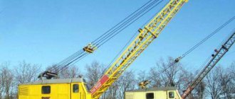
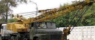
The KB-405 rail crane was developed in the middle of the last century at the Rzhev Mechanical Plant. The equipment became the prototype for the following modifications, which differed in load capacity, dimensions and scope of application. The main purpose of the tower device is the construction of residential buildings, engineering structures, shopping and sports centers. Subsequently, the products began to be used by commercial companies for the construction of high-rise facilities for entertainment and commercial purposes.
History and modification options
The production of construction equipment began in the mid-twentieth century under the USSR, when, due to the need to quickly build a large number of houses, the country's leadership began to invest money in the development of auxiliary equipment. The creation of KB 405 was directly undertaken by the Rzhev Crane Manufacturing Plant, which produces cranes of this series in modern Russia. In 1975, a new series of modified cranes KB 405 1 and KB 405 2 was released, and a few years later they were replaced by models KB 405 1A and KB 405 2A.
Tower crane KB 405 includes four main models
It is worth noting that the development and improvement of construction devices was very rapid, and literally nine years later in 1984, a modernized crane of the new KB-407HL series appeared. The production of this model was no longer undertaken by the RMZ, but by the Ukhta Mechanical Plant, which was provided with all the early developments and the basis of the 405 series crane. But soon the Rzhev plant again took up the creation of cranes, and today construction equipment is produced in the city of Rzhev, where the corporation’s main office is located.
You can purchase a tower crane of the KB 405 series in the following modifications:
- KB-405.1A.
- KB-405.1A-01.
- KB-405.1A-02.
- KB-405.2A.
Design and main characteristics
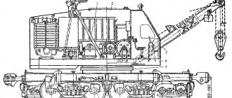
As for the design of the crane itself, it includes many different parts and technical elements; let's look at the most significant ones. First of all, the tower crane has four trolleys on which all additional superstructures are based. The KB 405 model is equipped with four special weather vanes, ballast plates, a portal, a running frame, a mounting stand and some other additions depending on the year and series of production.
Be sure to read: Truck cranes Galician: model range, technical characteristics
The running frame, or, as it is also called, the running part of the crane, consists of a non-rotating frame with four special eyes, whose main purpose is to further fasten the rotating beams or weather vanes. With the help of axes, the beams are attached to the eyes of the annular frame. During the working process, the weather vanes must be evenly spaced at an angle of forty-five degrees and fixed with special rigid tractors.
The main purpose of the crane is to fully mechanize cargo and lifting operations related to construction needs. According to official data from the plant, the maximum lifting capacity of the KB 405 crane is ten tons, and the permissible height is sixteen floors. It is worth noting that construction equipment is widely used in the Northern regions of the Russian Federation due to the possibility of operation in any climatic conditions. Temperature limits for KB 405: - 40 and + 40 degrees.
KB 405 mechanisms do not freeze even at record low temperatures
Returning to the external structure of the crane, you should pay attention to the slewing platform, which is more like a ring frame with additional beams attached. There are two fixed beams on the side of each part of the frame, and only one at the rear. Special cabinets with electrical equipment are located at the end of the turntable, where ballast reinforced concrete slabs can also be placed.
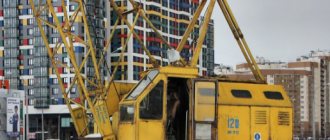
Thanks to its design, the KB 405 crane is a mobile, fully rotating unit with the possibility of quick installation and mobile installation. Construction equipment is easily transported using dolly carts in assembled form to any site and does not require additional maintenance.
Device
The design of the model includes two driving bogies and two driven bogies. These devices are characterized by a drive to one of the wheels with a gearbox and an electric motor, which is located on the side of the frame.
In addition, there are four weather vanes. These are important and necessary structural elements, characterized by a mobile state.
The weather vane looks like a box-shaped beam with a section varying in height. It serves to connect the running trolleys to the ring frame.
The sheet on top is turned towards the axis of movement. It is assembled from elements - working and transport eyes. These parts are necessary to securely fix the assembly to the ring frame.
At the point of support, trapezoidal weather vanes change height. Typically, the crane design uses several similar devices, located symmetrically relative to each other.
The support rings are securely fixed by welding.
- for lifting objects;
- operator cabin output;
- varying the distance from the crane axis to the load axis horizontally;
- torsion of the rotary base;
- movement of the object.
Chassis
The running frame is represented by a sheet system. It is motionless and equipped with four eyes located diagonally. Weather vanes that have removable features are securely attached here.
On one side, the pins of the running bogies are mounted using bushings. Since they are not fixed, they can be moved in a vertical plane.
If it is necessary to lock this structural element, then a special “finger” is inserted into the provided hole.
The specificity of using weather vanes is that they are located at an angle of 45 degrees diagonally from each other and are mounted on rigid tubular structures. In transport mode, these building parts are brought together and fixed or disassembled and delivered separately.
The ring frame is equipped with a switch. The KB-405 rotary support system is attached here to connect the chassis with the moving part. It has rings at the top and bottom, hardened balls in two rows and a gear-type crown.
The latter is characterized by engagement from the inside. Here is the runner gear of the reversal device.
The rotating base looks like a quadrangular structure. Beams are fixed to it by welding: two on the side and one on the back. The design has truss trusses. They are fixed on the side beams.
Trusses are made of hollow pipes, which are fixed by perpendicular connections. Their main purpose is to strengthen the tower portal. During its operation, the farms take on the main load.
Electrical equipment is located in the front area of the platform. There are special cabinets for this purpose. The portal is mounted right there on a pair of brackets.
Reinforced concrete ballast slabs are installed behind the swing base during crane assembly. Their number can reach ten pieces.
Reliable fastening of the plates is ensured by a system of rods, nuts and linings. The platform also houses rotation mechanisms and two winches. One of them serves the boom, the other - the loads themselves.
Tower
The tetrahedral crane tower has a lattice structure. It is made in the shape of a farm. Her device:
- middle and upper sections;
- structural elements designed to keep the structure from moving inward;
- portal;
- heads.
The tower is made of tubular elements united by specific diagonal and perpendicular braces. This unit is assembled using the method of building up from below. Inventory sections are mounted to the top sequentially.
The components of the tower look like lattice elements made by welding from seamless pipes.
The sections are decorated with steps and fences for safety of use. They all have similar dimensions, regardless of their location within the KB-405. At the same time, the upper section is distinguished by its shape, since it has openings for moving the operator’s cabin, mounted on movement mechanisms and hung on four lanyards.
The extension mechanism is a frame moving on rollers with a manual drive. The cabin is pulled out using a rope and a drum mounted in the opening using brackets.
The tower design includes a head and a structural element designed to keep it from moving inward (spacer).
Along with the operator's cabin, they have a functional significance for the entire device.
A metal lattice structure similar to a truss is called a cap. It is assembled from tubular parts using welding. At the top of this structure there are blocks and a cup anemometer.
To provide access to them for the purpose of prevention and repair, the manufacturer has provided dismantled stairs and platforms along the rear of the head.
There are eyelets at the bottom for hanging equipment. Behind the head there is a spacer with a guy and a suspension. They are securely fastened for safe use of the device.
Operator's cabin
The operator's cabin of the tower crane belongs to the remote type. Inside there is space for the crane operator with an adjustable chair.
Command controllers are provided to operate the machine. The manufacturer has also installed some devices to provide guidance on the safe use of the crane.
To increase operating comfort, the cabin is equipped with a heating system, air conditioning, alarm and lighting.
Structure of the portal and cradle
A tower portal is a metal structure consisting of two tiers and having spatial specificity.
The main parts for manufacturing are box-type beams and hollow pipes. All this is connected by welding. Diagonal beams are made using a special unfolding method.
The structural element is designed to allow the passage of inventory parts during crane installation. The portal has upper and lower belts, which are equipped with pull-out locks, hooks and mounting chains.
Special guides ensure vertical position. Four diverter locks allow this large structure to be securely placed on them.
The portal frame has dismantled diagonal beams in the lower part.
This part of the device is secured when installing the crane using two turntable brackets. Following this, using a pair of telescopic struts, it is brought to a standing position.
A cradle is mounted in the portal opening. It is equipped with special rollers. The main purpose of this structure is to assemble sections of the building.
The cradle looks like a welded frame with special shaped flanges. They are used to fix sections. These fasteners are located in the corners of the frame.
There are blocks on the cradle body on both sides. These form the tower extension pulley system. Blocks on the portal beams are also used for this.
The guides in the design of the unit are designed to move the cradle along them.
Working boom
One of the main parts of the structure - the boom - looks like a lattice truss with a triangular cross-section. It consists of sections from 5 to 8 m long. All of them have a telescopic structure. crane boom KB 405, its features
Four sections are used to assemble the crane:
- home,
- intermediate (2 pcs.),
- root
Fastening occurs through flanges installed in special holes.
Technical characteristics of KB 405
An important indicator of the crane’s power is the boom reach, which is twenty-five meters. It is important to note that this is only the maximum value, and in reality, with an average lifting capacity of, say, eighteen meters, the minimum would be approximately thirteen meters. As for the hook of the KB-405.2A series unit, the extremely low lifting value is 51.6 meters, and the load moment is 162 tm. With such indicators, the hook reach reaches an average of 63.5 meters. The KB-405.1A and KB-405.1A-01 models have the maximum load moment value, which is 187.5 tm. As for the KB 405 1AO2 unit, the maximum load moment will be 135 tm, and the load capacity will be nine tons.
Be sure to read: Technical characteristics of overhead cranes
The main crane tower is made in truss form and is a complex lattice mechanism. The entire structure is made of pipes connected by transverse and diagonal fasteners. Household, technical sections and additional superstructures are evenly installed in the lower part of the platform one after another.
Touching upon the detailed technical characteristics of the tower itself, it is important to consider the cradle and portal. The portal is a two-tier structure consisting of trusses and pipes. The overall structure has a special opening designed to move inventory sections during installation. Important: during installation, the structure must be secured with two brackets , and then the base must be transformed into a vertical position.
The seismicity of the area for the operation of KB 405 should not exceed 1-b points
The KB-405.2 model has the maximum number of intermediate sections - six sections, and the minimum number is three sections KB-405.1A-01. Cranes KB-405.1A and KB-405.1A-02 are equipped with five sections. The total weight of tower cranes varies from 113 to 115 kg, but the transport dimensions remain the same for all models: height - 4.2, width - 4.02, and length - 27.8 meters.
Tower
This crane element in the drawing looks like a lattice structure with four edges. It has the following elements:
- portal;
- the topmost and intermediate sections;
- head, as well as spacers.
The entire structure is tubular, connected by braces along with transverse/diagonal braces. The tower is mounted according to the principle of “building up”: individual sections are fixed sequentially, starting from the bottom element.
The portal of the tower is a spatial metal structure in two tiers, welded in the form of frames. It provides a technological opening with deployable beams. It is necessary to allow inventory sections to pass through during assembly. The two outermost belts of the portal are equipped with diverter locks, metal chains, and rollers.
When the tower is extended, these rollers hold it, while the release locks allow the elements of the tower to be fixed. Diagonal beams are mounted in the lower box-shaped section of the frame.
Tower sections are welded. This is a kind of lattice structure in which only seamless pipes are used. The stops of the sectional belts interact with the portal outlet locks during extension. The sections are joined to each other using shaped flanges, after which they are secured with reliable bolts. The flanged configuration allows the rollers to pass through the next section as it extends.
Each element is equipped with circularly fenced stairs. All components of the tower are equal in size, but the design of the uppermost part is somewhat different: it contains openings that allow the control cabin to move, and the rear and front sides are slightly changed. A removable driver's cabin is mounted inside, suspended on turnbuckles and then bolted.
Operation and accidents
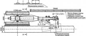
The tower crane is assembled using special jib-type equipment whose weight does not exceed sixteen tons. The installation steps for KB 405 are standard and are no different from the KBM-401 model. The remote control bullet helps to significantly speed up the assembly process and provides additional safety.
It is important to remember: before starting installation work, all holes and parts must be additionally cleaned and thoroughly lubricated with a special product.
Let's look at the main installation steps:
- First you need to prepare an area of 50 m by 20 m.
- Install crane tracks at a distance of no less than 4.7 meters from the nearest residential building or other construction site. The object must be removed at least thirty meters from power lines.
- Next comes grounding and leveling of the paths.
- After joining the sections and installing the portal, electrical installation work is carried out, and only after this the installation procedure itself begins.
- It is also necessary to install the working boom and check the condition of the ropes.
Be sure to read: Truck crane KS 45717
These are just a few basic installation points, and there are actually many more additional points to consider. You can see how the tower crane is installed on a construction site in the photos and videos presented below.
In the end, a few words should be said about accidents associated with the operation and installation of KB 405 cranes. To date, there are about ten high-profile incidents when, due to the negligence of workers and other related factors, serious accidents occurred. Therefore, it is very important to constantly check the condition of ropes and other parts , damage to which can lead to serious consequences.
Installation of a tower crane must be carried out with preliminary preparation and very carefully
Models
The model range includes:
- 160;
- 63;
- 80;
- 145;
- 125;
- 23B.
QTZ-160
Technical indicators and description of the QTZ-160 tower crane:
| Operating temperature | -40…+40°С |
| Maximum lifting weight | 10000 kg |
| Maximum load moment | 160 TM |
| Basic height of tower installation | 60000 mm |
| Section parameters | 2000x2000x3000 mm |
| Section | Angular profile |
| Largest working radius | 60000 mm |
| Capacity level at the center of the boom | 2400 kg |
| Hook lift height | 60000 mm |
| Working body overhang | 60000 mm |
| Boom equipment length | 60650 mm |
| Electric motor power consumption | 71 kW |
| Electrical system voltage | 380 V |
| Load moving speed | 63 m/min |
| Controls | Handles |
| Lowering depth | 17000 mm |
| Lifting speed | 6 m/min |
| Lowering speed | 8 m/min |
| International environmental standard | Euro 2 |
| Interwheel blocker | No |
| Allowable approach angle | 35° |
| Allowable departure angle | 27° |
Technical parameters and modification indicators of QTZ-63:
| Maximum load moment | 630 Nm |
| Load capacity level | 6000 kg |
| Maximum reach of boom equipment | 55000 mm |
| Free height | 40000 mm |
| Lifting speed | 30 m/min |
| Engine speed | 2600 rpm |
| Total weight of counterweight | 13500 kg |
| Electric power unit power | 24 kW |
| Working temperature | -40…+40°С |
| Maximum working radius of the crane | 50000 mm |
| Lowering depth | 15000 mm |
| Electric motor power | 56 kW |
| Electrical system voltage | 280 V |
| Lifting speed | 8 m/min |
| Lowering speed | 10 m/min |
| Section type | Corner |
| Ground clearance distance | 260 mm |
| Turning speed | 2.5 rpm |
| Smallest working area | 3m |
| Maximum torque | 1160 Nm |
| Overall turning radius | 22 m |
| engine's type | Electric |
QTZ-80
Technical characteristics of QTZ-80 tower crane:
| Maximum load moment | 800 Nm |
| Crane capacity | 6000 kg |
| Permissible weight at maximum boom reach | 1200 kg |
| Maximum reach of boom equipment | 56000 mm |
| Free height | 40000 mm |
| Maximum lift height | 150000 mm |
| Crankshaft speed | 2700 rpm |
| Total crane weight | 46400 kg |
| Counterweight | 15500 kg |
| Cargo winch power unit power | 24 kW |
| Rear cart winch motor power | 4.5 kW |
| Self-lifting equipment power | 5.5 kW |
| Operating temperature | -20…+40°С |
| Power supply voltage | 380 V |
| International environmental standard | Euro-3 |
| Minimum working radius | 3000 mm |
| Largest working radius | 60000 mm |
| Allowable wind speed | 20 m/s |