The kinematic diagram of an overhead crane allows you to understand the operating principles of all crane units and mechanisms. In general, the operating principle of all lifting and transport equipment is the same: the base is one or two metal beams on which a cargo winch is placed, driven by an electric motor.
The type of crane equipment depends on the type of structure and the specifics of the loads being lifted. However, it is worth noting that the main components of lifting mechanisms are similar.
Kinematic diagram of an overhead crane
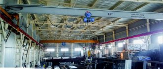
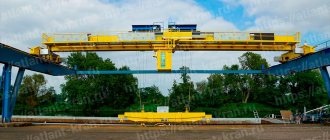
A crane is a device for lifting and vertically or horizontally moving loads over different distances. Depending on the types of construction, conditions and place of work, they are: bridge, jib, stacker cranes and cranes with load-bearing ropes. Overhead cranes have become widespread in the workshops of heavy and light industry enterprises. With their help, parts of various mechanisms, production containers, and tanks are lifted and lowered. As well as their movement along or across the workshop territory. Depending on the specifics of the production area and the type of cargo, the type of overhead crane that will be used is determined. At the same time, many components of the device, for example, the lifting mechanism, are of the same type for lifting equipment of this type. Which in turn makes their repair and maintenance easier. Kinematic diagram of an overhead crane , presented here, gives a clear idea of the design of the device and its components. In addition, no specialist will carry out installation and installation of the structure if there is no electrical and kinematic diagram of the overhead crane supplied by the manufacturer.
For information about discounts, current prices and product availability in stock, you can check with our specialists by calling (495) 661-2-555, or by sending a request to e-mail: [email protected]
In addition to the article Kinematic diagram of an overhead crane, read also:
Source
Kinematic diagram of an overhead crane with description
The kinematic diagram of an overhead crane allows you to understand the operating principles of all crane units and mechanisms. In general, the operating principle of all lifting and transport equipment is the same: the base is one or two metal beams on which a cargo winch is placed, driven by an electric motor.
The type of crane equipment depends on the type of structure and the specifics of the loads being lifted. However, it is worth noting that the main components of lifting mechanisms are similar.
Double girder overhead crane lifting capacity 12.5 t
nickitton
February 23, 2022
- 0
174
An example of a course educational project. Contains RPZ and drawings: section of the drum, layout drawing of the trolley, metal structure of the double-girder crane bridge, general view. Design of a double girder overhead crane. The work includes: calculation of the lifting mechanism, calculation of the trolley movement mechanism, design of metal structures. Ready drawings and
Overhead crane drawings
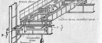
General kinematic diagram of an overhead crane
Rice. 1. Kinematic diagram of the overhead crane movement mechanism
Figure 1 shows a typical kinematic diagram of a crane mechanism, including:
- Electric motor (asynchronous three-phase motors are most often used).
- Brake – provides stopping and fixing of the moving load in any position.
- Gearbox – reduces the engine speed.
- Drum – serves for uniform tension of crane cables.
- A pulley block is a single one or a clip of several blocks that ensures efficient distribution of energy from the drive and gains in speed and strength.
- Hook – a device for grabbing a load.
General purpose overhead crane lifting capacity 20 t
Alyona
September 13, 2020
- 0
1 062
Drawings of a general-purpose overhead crane with a lifting capacity of 20 tons.
Overhead crane drawings
Kinematic diagram of the traveling mechanism of an overhead crane
Rice. 2. Transmission diagram of a crane with individual drive
The crane movement mechanism can be central or individual. In turn, the central movement is divided into two types: with a high-speed and low-speed transmission shaft.
Rice. 3. Kinematic diagram of the movement of an overhead crane with a low-speed transmission
The crane drive with a low-speed transmission is installed in the middle of the bridge and includes: engine 3, brake clutches 2 and gearbox 1. The output shaft of the gearbox is connected to the transmission shaft 4, made of prefabricated sections that are connected by couplings 5 installed in bearings. The couplings also connect the transmission shaft to the drive of the running wheels 7 using a gear 6. The shaft 4 rotates at the same speed as the wheels, transmitting maximum torque.
The movement mechanisms of cranes with a central drive, based on the type of transmission shaft, are divided into low-speed, medium-speed and high-speed transmission shafts.
The travel mechanism with a low-speed transmission shaft consists of a drive electric motor, a two- or three-stage gearbox and a transmission shaft. The transmission shaft usually consists of several sections, which are interconnected by gear couplings, and rests on intermediate supports mounted on the crane bridge. The transmission shaft is connected to the output shaft of the gearbox and the drive wheel using gear couplings. The brake is installed either on the coupling of the electric motor shaft with the input shaft of the gearbox or on the free end of the electric motor shaft. The use of gear couplings, as well as supports with self-aligning bearings, makes it possible to obtain the necessary alignment of the inserts being connected and ensure normal operation of the transmission shaft. The transmission shaft of the travel mechanism has a rotation speed equal to the rotation speed of the drive wheels and transmits significant torque, so the shaft, couplings and supports are large, and the mechanism has a large mass. Despite these disadvantages, travel mechanisms with a low-speed transmission shaft are widely used on overhead cranes for general and special purposes, especially on truss bridges.
The movement mechanism with a mid-speed transmission shaft (Fig. 28.6) is equipped with a gearbox with a lower gear ratio than the gearbox in Fig. 28a, which makes it possible to reduce by several times the torque transmitted by the transmission shaft from the engine and, therefore, to use couplings, support bearings and inserts of smaller sizes. To transmit torque from the transmission shaft to the drive wheels, open gears are used, consisting of gears mounted on the ends of the transmission shaft and ring gears mounted on the wheels or additional end gears located near the wheels.
The use of couplings, intermediate supports and inserts of smaller sizes makes it possible to reduce the weight of transmission shaft components. However, the use of additional open gears or end reducers does not lead to a significant reduction in the total mass of the mechanism. Movement mechanisms with open gears, which have low durability, have not found widespread use.
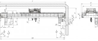
Rice. 1. Diagram of crane movement mechanisms: a - with a low-speed transmission shaft; b - with a mid-speed transmission shaft; c - with a high-speed transmission shaft; g - separate drive
The travel mechanism with a high-speed transmission shaft has a drive electric motor installed in the middle of the crane bridge, which is directly connected to the transmission shaft by gear couplings. The ends of the transmission shaft are connected to the input shafts of gearboxes located near the drive wheels. The output shaft of the gearbox is connected with gear couplings to the wheel directly or using an intermediate low-speed shaft. In the considered diagram of the movement mechanism, the transmission shaft of this movement mechanism has a rotation speed equal to the rotation speed of the drive electric motor. Compared to the locomotion mechanisms shown in Fig. 1, a, b, it transmits the smallest torque. This makes it possible, with the same drive motor power, to reduce the diameter of the transmission shaft by 2-3 times compared to a low-speed shaft and reduce its weight by 4-6 times. The total mass of the travel mechanism with a high-speed shaft, despite the presence of two gearboxes for large spans, will be less than the mass of the travel mechanism with a low-speed shaft.
However, due to the high rotation speed, the installation of a high-speed shaft requires special precision in its manufacture, balancing and installation, and the use of supports of increased rigidity that prevent the formation of misalignment when the bridge is deformed (as a result of misalignment) of the crane in the horizontal plane. Therefore, moving mechanisms with a high-speed shaft are used on overhead cranes with spans not exceeding 20 m.
The movement mechanism with a separate drive has found widespread use on overhead girder cranes for general and special purposes with spans of more than 15 m. It consists of two or more independent drives installed on the working platforms of the bridge near the end beams and serves to drive one or more running wheels. The use of a separate movement mechanism eliminates the need for long transmission shafts and reduces installation and operating costs. With a separate drive, each end beam of the bridge is driven by its own drive, and the connection between the drives is carried out through the metal structure of the crane. Each drive consists of an electric motor, brake, gearbox and drive wheel. For ease of installation and compensation for misalignment of the connected shafts of the gearbox and the running wheel, gear couplings and a low-speed shaft are used, or Hooke's joint-type couplings and cardan shafts are used.
Compact drives made in the form of a mounted vertical gearbox mounted on the splines of the drive wheel shaft and a flanged electric motor have found wide application in separate movement mechanisms. The brake is installed on a stand fixed to the gearbox or the coupling of the motor shaft with the gearbox.
The movement mechanisms of overhead crane trolleys are made according to the crane movement mechanism with a low-speed transmission shaft with a central or cantilever arrangement of a vertical gearbox on the trolley frame. The torque from the electric motor is transmitted through a gearbox to a transmission shaft connected to cylindrical drive wheels, or is transmitted directly to the drive wheel of the trolley, which is connected to another drive wheel by a transmission shaft.
Rice. 2. General view of the separate drive of the traveling mechanism of the overhead crane: a - with a vertical gearbox and a gear coupling; b - o horizontal gearbox and high-speed cardan shaft
Rice. 3. Scheme of a separate drive with a flanged electric motor and mounted gearbox
One of the most important elements of the chassis of rail-based movement mechanisms, which also include the movement mechanisms of overhead cranes and theirs. trolleys are running wheels. For the movement mechanisms of overhead cranes, running wheels with side ledges - flanges - are used. When using flangeless running wheels, the crane running gear is additionally equipped with devices that hold the crane on the rail track.
The running wheels of overhead cranes and trolleys are made of steel, single- or double-flanged, with a cylindrical or conical tread. Double-flanged running wheels with a cylindrical tread have become predominant. Main dimensions of double- and single-flanged steel solid-rolled and stamped cylindrical running wheels (GOST 3569-74).
To compensate for inaccuracies in the laying of crane tracks, installation of metal structures, etc., the width of the cylindrical track of single- and double-flanged running wheels for crane travel mechanisms should be 30 mm greater than the width of the rail head, the conical track by 40 mm, and the running wheels of trolleys by 15-20 mm.
The running wheels of cranes and trolleys are heavily loaded and wearable elements of the running gear. Therefore, high demands are placed on the materials from which they are made, as well as on their processing and installation.
Rice. 4. Diagram of the drive mechanism of the trolley movement: a - with a central location of the vertical gearbox; b - with a side-mounted vertical gearbox 32. Main dimensions (mm) of crane wheels (GOST 3569-74)
The running wheels of cranes and trolleys are made from stamped or solid-rolled blanks of steel 75, 65G (GOST 14959-79). Solid-rolled wheels have approximately 1.5 times the durability of stamped wheels. To ensure high hardness (HB 300-360), the running wheels are subjected to heat treatment to the following depth: for a wheel diameter of 200-250 mm - 15 mm; 320—500 mm—20 mm; 560-710 mm - 30 mm; 800-1000 mm - 40 mm. For running wheels intended for cranes in heavy and very heavy operating modes, hardening with high-frequency currents is used, and for wheels of cranes in medium and light operating modes, normalization is used. The surface treatment of the rolling surface must correspond to the 11th grade.
When misalignment occurs in a crane equipped with cylindrical drive wheels, the flanges come into contact with the head of the crane rail, limit further misalignment and are subjected to high friction loads, causing their rapid wear. Therefore, to reduce friction and wear, some designs of overhead cranes use devices for lubricating flanges and rail heads.
When misalignment occurs in a crane with drive conical running wheels installed at the top of the cone outside the span, contact with the rail of the drive wheel of the leading side of the crane is made along a smaller diameter, and the wheels of the lagging side are made along a larger diameter. At the same speed of rotation of the drive wheels, the speed of movement of the lagging side of the crane increases, and the leading side decreases. This leads to the alignment of the crane on the tracks without interaction of the flanges with the rails and helps to increase the service life of the running wheels.
An important influence on the wear of the flanges of the running wheels is the accuracy of the installation of the running wheels on the crane and the correct laying of the rail track. The misalignment of at least one of the running wheels contributes to a more intense misalignment of the moving crane and friction of the flanges on the heads of the crane rails. If the crane tracks are inadmissibly narrowed or widened, intensive wear of the flanges of the running wheels is also observed, and sometimes the crane jams, leading to breakdown of the running gear. Therefore, crane operators and repair services, when the running wheels wear out intensively, should first of all pay attention to their installation and the condition of the crane tracks. In accordance with GOST 24378-80 E, the skew angle of the running wheel relative to the axis of the end beam should not exceed 0.002 rad; maximum angular deviation of the supporting surfaces of the axle plates for roll-out axle boxes is 0.002 rad. The accuracy of laying the crane runway is regulated by the Rules.
Drive wheels are mounted on shafts that transmit torque from the drive to the wheel, and non-drive wheels are mounted on rotating axles that do not transmit torque. The shafts or axles of the running wheels are mounted on bearings in housings called axle boxes.
Axleboxes, made removable and detachable, are designed to secure the running wheels on the trolley frame, end beams of the crane bridge or balancers. The use of removable axle boxes makes it possible to simplify the replacement of road wheels during repairs by disconnecting the axle boxes from their mounting points and then rolling out the road wheel. The most widespread installation is on corner detachable axle boxes.
Rice. 5. Crane running wheels: a - drive; b - non-drive
When installing flangeless running wheels, horizontal guide rollers are used as elements limiting the movement of the crane along the rails. Guide rollers are installed on end beams or balancers in close proximity to the running wheels in two versions: on both sides of the rail or on one side facing the span. Thanks to the use of guide rollers, friction losses are reduced compared to flange wheels, since in this case the sliding friction of the flanges on the rail head is replaced by the rolling friction of horizontal rollers on the rail. The complexity of the chassis design is compensated by a decrease in drive power (due to a decrease in movement resistance) and an increase in the service life of the running wheels.
The diameters of the running wheels used for travel mechanisms of cranes and trolleys in accordance with the current standard must not exceed 1 m, and therefore the maximum permissible load on the running wheel is also limited. For overhead cranes and trolleys with a lifting capacity of up to 50 tons, the chassis is made with four running wheels, for cranes with a lifting capacity of 80 tons with eight, and for cranes with a lifting capacity of 160 tons and more - with 16 wheels.
To ensure uniform distribution of loads on the running wheels, the running gear of heavy-duty overhead cranes is mounted on balancing beams. Running wheels on axle boxes are installed in pairs on balancing trolleys and are pivotally connected by horizontal axes either to the end beam of the crane or to the main balancer, which in turn is pivotally connected to the end beam. The drive of such a multi-wheeled undercarriage is central or separate and is carried out by one or more movement mechanisms. All wheels, as well as half or a quarter of the total number of running wheels, can be driven. An important condition for the use of several movement mechanisms is to ensure synchronous rotation speed of all drive wheels.
On moving mechanisms, horizontal gearboxes Ts2, vertical gearboxes VK and VKU are used, which are rigidly bolted to the metal structure of a crane or trolley, and vertical gearboxes VKN with a hollow output shaft, with internal splines or a keyway designed for connection to the shaft of the travel wheel.
Rice. 6. Chassis of the movement mechanism with horizontal rollers: a - general view of the chassis with a balancer; b - installation of a horizontal roller
Rice. 7. Installation of traveling wheels of an overhead crane on balancing trolleys: a - eight-wheeled; 6 - sixteen-wheeler
When installing flangeless running wheels, horizontal guide rollers are used as elements limiting the movement of the crane along the rails. Guide rollers are installed on end beams or balancers in close proximity to the running wheels in two versions: on both sides of the rail or on one side facing the span. Thanks to the use of guide rollers, friction losses are reduced compared to flange wheels, since in this case the sliding friction of the flanges on the rail head is replaced by the rolling friction of horizontal rollers on the rail. The complexity of the chassis design is compensated by a decrease in drive power (due to a decrease in movement resistance) and an increase in the service life of the running wheels.
The diameters of the running wheels used for travel mechanisms of cranes and trolleys in accordance with the current standard must not exceed 1 m, and therefore the maximum permissible load on the running wheel is also limited. For overhead cranes and trolleys with a lifting capacity of up to 50 tons, the chassis is made with four running wheels, for cranes with a lifting capacity of 80 tons with eight, and for cranes with a lifting capacity of 160 tons and more - with 16 wheels.
Kinematic diagram of the overhead crane lifting mechanism
In bridge-type crane structures, the lifting mechanism is placed on a load trolley. The number of lifting devices depends on the maximum weight of the load that the machine can lift.
The lifting scheme of lifting and transport equipment depends on a number of factors: the type of gripping device, the height and weight of the load being lifted, and the length of the span. When using a hook, grab or electromagnet, one lifting mechanism is used.
Rice. 4. Kinematic diagram of lifting an overhead crane with a hook
- Engine
- coupling
- Brake
- Gearbox
- Drum
- Pulley hoist
- Fixed pulley block
For lifting in cranes, normal and shortened hook hangers are used.
Overhead crane lifting capacity 5 t.
Max
September 6, 2021
- 80
13 919
In the educational project, an overhead crane was designed and calculated. Load capacity 5 m, lifting height 6 m, span 16.5 m. A crane trolley was chosen as the unit to be modernized. Based on the calculation results, based on a comparison of all possible options for its parameters, the optimal option was selected and the economic benefits from
Overhead crane drawings / Cranes
Kinematic diagram of an overhead crane trolley
Rice. 5. Kinetic diagram of the cart
The load trolley is responsible for lifting and moving the working part of the crane. They are designed for use on both single and double beam structures.
The diagram in Figure 5 shows the principle of moving the trolley. The electric motor 1 transmits torque to the drive wheels 11 through clutches 2,8,9,10. To reduce the number of revolutions, gears with 3-6 oblique teeth are used. Brake 7 blocks the transmission of torque and stops the cart.
The importance of reading the kinematic diagram is emphasized by the fact that reading it is mandatory for all students in the direction of “Lifting and transport machines and equipment”. Designing and calculating cranes and writing coursework is impossible without understanding the principles of operation of the mechanism.
General kinematic diagram of an overhead crane
Rice. 1. Kinematic diagram of the overhead crane movement mechanism
Figure 1 shows a typical kinematic diagram of a crane mechanism, including:
- Electric motor (asynchronous three-phase motors are most often used).
- Brake – provides stopping and fixing of the moving load in any position.
- Gearbox – reduces the engine speed.
- Drum – serves for uniform tension of crane cables.
- A pulley block is a single one or a clip of several blocks that ensures efficient distribution of energy from the drive and gains in speed and strength.
- Hook – a device for grabbing a load.
Double girder overhead crane lifting capacity 16 t
sitashokage
January 22, 2022
- 0
597
Educational project. Contains RPZ and drawings: overhead crane (general view), metal structure of the end beam (SB), trolley movement mechanism (SB). During the course work, the principle of designing an overhead crane was studied. An analysis of literary and patent sources on the designs of overhead cranes was carried out. The main parameters are also calculated
Overhead crane drawings
Kinematic diagram of the traveling mechanism of an overhead crane
Rice. 2. Transmission diagram of a crane with individual drive
The crane movement mechanism can be central or individual. In turn, the central movement is divided into two types: with a high-speed and low-speed transmission shaft.
Rice. 3. Kinematic diagram of the movement of an overhead crane with a low-speed transmission
The crane drive with a low-speed transmission is installed in the middle of the bridge and includes: engine 3, brake clutches 2 and gearbox 1. The output shaft of the gearbox is connected to the transmission shaft 4, made of prefabricated sections that are connected by couplings 5 installed in bearings. The couplings also connect the transmission shaft to the drive of the running wheels 7 using a gear 6. The shaft 4 rotates at the same speed as the wheels, transmitting maximum torque.
What does an overhead crane consist of?
The general structure of an overhead crane is a single- or double-girder bridge and a load trolley that moves along it.
Electrical equipment and main components and mechanisms are placed on the bridge and on the trolley.
Brake system
The standard braking system for bridge PMGs is block or disc-block.
Functionally, the braking devices of cranes are locking - to stop the device - and release - slowing down the descent.
Brakes can be open or closed types. The lifting mechanisms of cranes are equipped with closed brakes - in the normal position the mechanisms are braked, the brake is released only when the engine starts.
Closed type brakes are used in hydraulic and mechanical engineering because they are more durable than open ones and their failure can be easily noticed.
In some cases, open brakes are mounted in addition to closed ones (as auxiliary ones) to increase the speed and accuracy of load placement.
Lifting mechanisms
The mechanism for lifting and lowering the load is also located on the crane trolley.
It consists of a drive electric motor, transmission shafts, a horizontal gearbox and cargo cables with a winding drum.
For work with loads >80 t, additional overhead crane gearbox or reduction gear. To increase the traction force, a chain hoist is used (most often a double multiple).
Overhead crane gearbox, its purpose and design
Functionally, cylindrical crane gearboxes can be divided into:
- lifting gear reducers;
- trolley motion reducers;
- axle motion reducers.
The gearbox may have 2 types of execution: unfolded and planetary.Reducers of the deployed type, equipped with cylindrical wheels, are more popular. Repair and maintenance of mechanisms of this design are simpler and cheaper.
Crane tracks for overhead cranes
When constructing a crane track, railway rails P18, P24, P38 (narrow gauge) and P43, P50 and P65 (for wide gauge) are used as crane and trolley rails.
They also use special crane rails KR50, KR70, KR80, KRYUO, KR120, or square steel guides with rounded edges (for mechanisms with lifting capacity ≥ 20t).
I-beams are used as crane tracks for suspended type GPM.
Attachments of rails to beams must prevent movement of the rails and must allow the quick replacement of worn rails. Their ends are connected with double-sided plates and bolts or welded.
Electrical equipment
Special, increased requirements are imposed on the electrics of bridge PMGs, which is due to intense operating conditions.
In 1 hour, hundreds of switching on, switching off and overloads associated with acceleration and braking of the device as a whole or the cart can be performed.
The movement of the bridge and crane trolley, lifting and moving the load is carried out by the main electrical equipment:
- electric motors 3 (4) motors are installed, 2 of them are placed on the trolley to lift/lower the load and move the trolley along the bridge beam, and 1 (2) motor moves the crane beam along the rails. In overhead cranes for operational testing, durable asynchronous electric motors are used, designed for frequent overloads and starts of the MT or MTK series (for light work), three-phase current;
- electromagnets , pushers and other devices involved in the operation of holding brakes;
- limiters and other mechanical protection.
controllers , control relays, magnetic starters and other equipment to control electric motors;
Kinematic diagram of the overhead crane lifting mechanism
In bridge-type crane structures, the lifting mechanism is placed on a load trolley. The number of lifting devices depends on the maximum weight of the load that the machine can lift.
The lifting scheme of lifting and transport equipment depends on a number of factors: the type of gripping device, the height and weight of the load being lifted, and the length of the span. When using a hook, grab or electromagnet, one lifting mechanism is used.
Rice. 4. Kinematic diagram of lifting an overhead crane with a hook
- Engine
- coupling
- Brake
- Gearbox
- Drum
- Pulley hoist
- Fixed pulley block
For lifting in cranes, normal and shortened hook hangers are used.