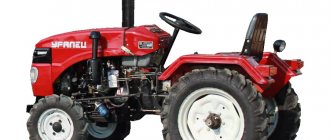
DT-20 is a Soviet-made universal tractor designed for multi-purpose use. Even despite the light towing category, the car has good performance, which is not surprising. After all, it was in great demand throughout the Soviet Union, and this is perhaps the key confirmation of the success of the DT-20 tractor. The equipment is a light wheeled tractor from the Kharkov Motor Plant, produced from 1958 to 1969. This car is usually classified as 0.6 traction category. The capabilities of this device are designed for a wide range of tasks in agriculture, as well as other fields of activity. Let us consider in detail the advantages of the machine, as well as its capabilities and characteristics.
Article navigation
- 1 Description and purpose
- 2 Brief characteristics of the DT 20 tractor
- 3 Features of design and operation 3.1 Modifications of the DT 20 tractor
Purpose
The main purpose of the DT-20 is the mechanization of excavation work, increasing productivity and the ability to develop a large amount of virgin land. At its level, the tractor coped with these tasks. The first tractors with metal wheels produced were scattered across museums in many cities. But it won’t be superfluous to say that even in 2022 there are still working copies.
Tractor DT 20
User manual
Maintenance
Uninterrupted and long-term operation of the tractor is ensured by timely and high-quality technical inspections and maintenance procedures. The car is cleaned of dirt, refueled and lubricated. The condition of systems and units is regularly checked, and any detected defects are eliminated.
The maintenance rules provide:
- periodic maintenance measures carried out after certain periods of operation (duration is calculated based on the amount of fuel consumed and the duration of engine operation),
- Shift care is performed at the start and during team breaks.
Maintenance of equipment operating with the unit is carried out regularly according to the instructions in the operating manual.
Table. Regular maintenance of the DT-20 tractor
Conservation
It is not advisable to use DT-20 in winter. The engine preservation procedure involves draining oil, fuel and spent fuel. The entire machine is cleaned and washed, the mechanisms and elements are dried and lubricated.
Basic problems, troubleshooting methods
The motor does not turn on:
- low quality or lack of fuel and oil,
- the fuel or air filter is clogged,
- The fuel pump does not work.
The hydraulic system does not work:
- not enough oil
- hydraulic pump is switched off,
- The safety valve is jammed.
Starter failure:
- weak contact of the magnetic switch,
- battery is low,
- wire break,
- short circuit.
If the brake system fails, it is necessary to replace the discs or reduce the pedal stroke.
Specifications
The DT 20 tractors became the prototype for modern machines. And on its basis new modifications were designed: DT-25, DT-75. The weight of the DT-20 is 1.56 tons, and it is designed in two versions:
1. Raised design for garden work:
- length 1.63-1.775 m;
- hood height 1.231 m;
- clearance 0.515 m.
2. Low design, for garden work:
- length 1.423-1.837 M;
- height 0.308 m;
- clearance 0.308 m.
The length with the hanging system is quite compact 2.8-3.0 meters.
Engine characteristics
The most important detail is that the engine has the following characteristics:
- single-cylinder d-125 mm, piston stroke 140 mm;
- power 13.2 kW;
- 4-stroke;
- electric starter;
- single-section fuel pump with a combined lubrication system (pressure and splash);
- traction force 0.125-0.72 tons.
An important feature that can be attributed to factors that increase the safety of the machine is the forced-type water cooling installed on a low-power engine, which prevents the engine from heating up in the hottest weather.
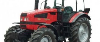
Be sure to read: Tractor Belarus 3522
The power unit develops speed in 3 modes:
- Normal – 18 hp. 1600 rpm – 5-15.6 km/h;
- Maximum 1800 20 hp – 17.65 km/h;
- An additional gear is used for a PTO of 900 rpm - 0.87 km/h.
Cabin
The design does not include a cabin, which allowed engineers to save on metal structures and glazing, as well as reduce the load on the ground. The protective function was performed by the awning. The chair was rigidly attached to the frame, and in terms of convenience it did not offer any advantages or advantages, even minimal ones.
Fuel consumption
The single-cylinder engine is the most economical in its family, its consumption is 200 g/l.s*hour. The estimated operating time of a full tank of 45 liters is 12.5 hours.
Characteristics
| Model | DT-20 |
| Engine | D-20 |
| Power, hp (kW) | 20 (14,6) |
| Fuel consumption, g/l. With. at one o'clock | 200 |
| Number of forward/reverse gears | 6 / 5 |
| Forward speed range, km/h | 5,0 — 17,7 |
| Dimensions, mm | 2818/3038 x 1300 x 1231/1438 |
| Weight, kg | 1500 |
Device
A distinctive feature of this tractor from all modern models is the absence of a frame. Its core is the engine, gearbox, rear axle, on which all attachments are installed: wings, seat, fuel tank and, of course, controls:
- steering wheel;
- levers: - ex. clutch; — gear shifting; - reverse;
- pedals: — brakes (right and left); — gas (manual and foot).
The controls have built-in pedal brakes – band brakes with separate controls. The tractor's capabilities are not limited to standard forms; it has the ability to adjust ground clearance and be combined with trailed and mounted equipment.
Chassis : driven rear wheels, front guides rigidly connected to the front axle, which balances vertically - a kind of shock absorption. A manual transmission with a single-plate friction clutch is controlled by a lever. When reverse is engaged, the tractor goes backwards at full speed of 16 km/h, control is carried out in mirror image.
Tractor DT 20 with trailer
Tractor DT-20
The Kharkov Tractor Plant produced this tractor model for twelve years, ceasing its production in 1969. During this time, almost two hundred and fifty thousand new tractors saw the light, and some of them went to work abroad: to Holland, France and other countries. This machine (0.6 ton class) was intended mainly for gardening and gardening work.
Its design is distinguished by the absence of a frame, pedal-type brakes, and a water-cooled diesel engine (due to which the car hardly heats up even in the heat). Adding functionality is a wide variety of working equipment, adjustable track (both front and rear wheels), variable clearance, grip weight and longitudinal base.
These positive qualities, compactness and the fact that the domestic tractor could easily be changed into reverse, made the unit very popular, not only in agriculture and forestry, but also among utility workers and builders.
Some disadvantage is the lack of a cabin (which was partially compensated by the presence of an awning in a number of modifications). The tractor cannot boast of the high power of its single-cylinder engine (it is only 18 horsepower). Photo of the DT-20 tractor
There were quite a lot of tractor modifications. They differed in rear tires, electrical equipment, and attachments:
- DT-20-S1 with 8-32 tires was used for plowing rows.
- DT-20-S2 with 10-28 tires, which have excellent grip on the ground, were used for general purpose work and transport.
- DT-20-S3, DT-20-S4 and DT-20-S5 with 10-28 tires and widened fenders are export models.
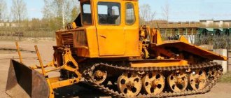
- DT-20V is a tracked version of the tractor for use in vineyards.
- DT-20K with a ground clearance of 1.5 meters and a wide track (2.1 meters) is a model for working with tall plants.
- DT-20U was used where row spacing was narrow. It was convenient to use this tractor on farms.
What can be included with
The T 20 tractor was manufactured in various modifications, but nevertheless additional equipment could be supplied to it:
- sprayers;
- trailer trolleys;
- mowers;
- plows;
- harrows;
- hillers;
- vine transporter.
Rare tracked version of the DT 20 tractor
Specifics of account 20
Account 20 is active. By debit, it reflects the costs of main and auxiliary production, administrative and management expenses, losses from defects, etc. It corresponds with the credit of the accounts:
- material - count. 10;
- accounting for salary settlements (account 70), with funds (account 69), suppliers/contractors (account , );
- losses from defects (account 28), shortages (account);
- expenses of service farms (account 23,);
- general production and general economic costs (account 25, ) etc.
On loan account 20 record the write-off of the cost of products/works/services to the debit of the accounts of finished products (account 43), sales (), etc.
A feature of account 20, as an accounting position, is that its debit turnover cannot exceed the credit turnover, since it is impossible to write off expenses (consume resources) more than they are produced (transferred from the warehouse to the production of products). Those. There cannot be a credit balance on the account. The debit balance reflects the amount of the existing “work in progress” at the end of the period.
Correct accounting of accounts. 20 presupposes the availability of competent analytics by types of costs and manufactured products/works/services, and, if necessary, by workshops and sections.
content .. 31 32 36 ..MAIN TRANSMISSION OF THE DT-20 TRACTOR - PART 2
At the bottom of the main transmission, under the intermediate and main shafts, there is an additional transmission unit (Fig. 81). The drive roller 5 of the additional gear is located along the axis of the tractor, parallel to the input shaft of the main gear, and rotates in two radial ball bearings 7 and 10. In the front part of the drive roller, a constant meshing gear 1 of the additional gear is installed on splines. The gear is seated all the way into the spring retaining ring 8 on the drive shaft.
The inner ring of the front bearing 7 is placed on the cylindrical end of the shaft, and the outer ring is pressed into the bearing seat 3 until it touches the shoulder. A retaining spring ring inserted into the annular groove of the socket secures the bearing ring from axial movements. The bearing seat is installed in the bore of the front wall of the main gear housing, closed with a flat cover and attached together with it to the crankcase. Adjusting shims 2 are placed under the socket flange in the crankcase recess.
Rice. 81. Additional (slow) gear drive:
I — driven gear of constant mesh; 2 — adjusting shims; 3 - bearing seat; 4 - cover; 5 — drive roller of additional transmission; 6 - thrust ring; 7 - ball bearing; 8 and 9 — retaining spring rings; 10 — bearing; 11 — driving bevel gear of additional transmission; 12 — retaining spring ring; 13 — power take-off shaft; 14 — driven bevel gear of additional transmission; 15 — bearing; 16 — retaining ring; 17 — movable gear of additional transmission; 18 — retaining ring; 19 — bearing; 20 — bearing cup; 21 — adjusting shims; 22 - cover; 23 — retaining ring
A thrust ring is installed between the gear hub 1 and the inner ring of the bearing. In the middle part of the drive roller, between two retaining spring rings 9 and 12, there is a bearing 10, and on the splines of the roller there is a driving bevel gear 11 of the additional gear. The outer bearing ring is mounted in a boss inside the final drive housing. The free splined end of the drive shaft of the additional transmission is connected by a splined sleeve to the power take-off shaft 13.
The driven bevel gear 14 of the additional gear is made together with a splined shaft and rotates on two ball bearings. The inner bearing 15 is installed in a boss inside the crankcase and secured to the shaft near the bevel gear with a retaining spring ring 16. The second bearing 19 is installed on a shaft between two retaining rings. The outer ring of this bearing is located in cup 20 of the main gear housing.
The cup cover 22 clamps the outer ring of the bearing and closes it. It is attached together with the glass to the main gear housing. Adjusting shims 21 are placed under the flange of the cup 20. By changing the number of shims 2 and 21, the gap between the teeth of bevel gears 11 and 14 is adjusted.
Spur gear 1 of drive roller 5 is in constant mesh with spur gear 8 (Fig. 78) of the main gear input shaft and rotates in one direction. Together with gear 1 (Fig. 81), the drive shaft and bevel drive gear 11 rotate, with which the driven bevel gear 14 is in constant mesh. A spur gear 17 with an annular groove for the shift fork is freely mounted on the splined part of the shaft of this gear. This gear, when moving along the shaft splines, meshes with spur gear 39 (Fig. 78) of the first gear, located on the main shaft. When the additional gear is engaged, rotation from the engine is transmitted through the constant mesh gears to the drive shaft 5, bevel gears 11 and 14, drive gear 17 and to the driven gear of the first gear of the main shaft (Fig. 81). From the main shaft, rotation is transmitted to the differential and drive wheels of the tractor. The speed of the tractor in this case will be very low, so the additional transmission unit is not designed to operate a tractor with a traction force of more than 700 kg. The additional gear is activated by moving the movable gear on the additional gear shaft. The reverse is switched by moving the gear coupling of the reverse mechanism on the gear sleeve.
To move the carriages and gears, gear shift forks mounted on the shift rollers are used (Fig. 82).
The lower ends of the forks freely fit into the annular grooves on the gears, carriages and on the gear coupling of the reverse mechanism. The shift rollers are located above the intermediate and main shafts and move in the holes in the side walls of the main gear housing. The ends of the rollers emerging from the main gear are covered with covers 12. The shift forks, as well as additional guides, have slots into which the ball end of the gear shift and reverse levers fits. The front roller 1 is equipped with a fork 2 for shifting the first and fourth gears, made together with a leash. Fork
secured to the shaft with a bolt 11, which tightens the fork hub on the shaft, and the cylindrical part fits into the recess of the shaft.
Roller 4 has a driver 3 of the second and third gears and a fork 5. On the shaft 6 there is a fork 10 for engaging the additional gear, and on the roller 8 there is a fork 9 for switching the reverse and a driver 7 of the reverse shift roller. To hold the gears in the off or on positions, the rollers at the right ends have recesses into which conical stops or locking mechanism detents fit. There are three indentations on the shift rollers for first and fourth, second and third gears. The middle ones are designed to fix the rollers in the off, or neutral, position. The extreme recesses fix the engaged position of the gear. There are two grooves on roller 6, since they only engage one gear.
Rice. 82. Shift rollers and forks:
On the reverse activation roller 8 there are also two recesses that fix
the position of the clutch fork of the reverse mechanism when turning on the reverse to move forward or backward.
The locking mechanism (Fig. 83) consists of a housing 6 and a roller 1, the latter can move in the housing along the axis of the tractor above the shanks of the clamps. There are holes made on the cylindrical part of the roller into which the cylindrical shanks of the clamps fit. Clamps 4, equipped with conical heads and cylindrical shanks, are inserted into the holes of the main gear housing in the right front part. The shanks fit into the holes of the locking housing 6, and the housing mounted on the main gear housing closes the clamps with springs 5. They press the clamps against the gear shift rollers. The clamps, falling with their conical part into the recesses of the shift shaft, fix it and the fork in a position corresponding to the complete engagement or disengagement of the gear. This eliminates the possibility of turning on and off the gears and the reverse gear clutch while driving with the clutch engaged, as well as the spontaneous disengagement of the gears and the reverse gear clutch under load while the tractor is moving.
Rice. 83. Locking the gear shift and reverse mechanism: 1-valve lock; 2— felt seal; 3 - lock bolt; 4— latch; 5—clamp spring; 6 — blocking body; 7 - spring ring.
To limit the stroke of the locking roller and keep it from turning, use a locking bolt 3, the shank of which fits into
longitudinal groove of the roller. Felt seal 2 installed in the locking body protects parts from contamination. The oil seal is held in the housing by a washer and a spring ring 7. The shaft has holes for a rod connecting it to the clutch control lever.
When the clutch is engaged or when it is not completely disengaged, the holes in the locking body, into which the cylindrical shanks of the clamps fit, are blocked by the locking roller 1. Therefore, the clamps cannot rise up from the recesses of the shift rollers; the latter will not move and engage or disable gears or shift the reverse clutch. Moving the rollers, engaging gears or changing reverse is possible only when the clutch is disengaged. In this case, the locking roller will move forward and the holes in it will be located above the cylindrical shanks of the clamps. When moving the shift roller, the lock will come out of the roller recess and its shank will fit into the hole of the lock roller. If the gears of the engaged transmission are not fully engaged, the lock will not completely lower into the recess on the roller, the cylindrical shank of the lock will not come out completely from the hole of the locking roller and it will not be able to move along the axis. Therefore, the clutch control lever cannot be moved to engage the clutch.
To change gears and reverse, use a mechanism (Fig. 84) mounted in the top cover of the main gear. On the left side of cover 1 there is a gear shift lever 7. It is welded to gear shift shaft 3 and together with it can move and rotate in the holes in the top cover. The inner lever 4 is secured to the shaft inside the cover with a coupling bolt 9 and a key 11.
gear shift. Its ball head fits into the slots of the forks and the driver of the gear shift rollers.
Rice. 84. Top cover with gear shift and reverse mechanism:
1- top cover of the main gear; 2 - filler plug; 3 — shaft of the gear shift lever; 4 — gear shift lever; 5 — felt seal; 6 — reverse switch lever; 7 — gear shift lever; 8 - drawstring; 9 — coupling bolt; 10 — reverse switch lever; 11 - key; 12 - ball; 13 - plug; 14— spring; 15—reverse switching roller; 16—installation bolt; 17 — felt seal; washer.
By moving lever 7 with the gear shift roller along the tractor, the ball head of lever 4 can be installed in the slot of one of the drivers of the first three gear shift rollers. By turning the shift shaft, you can use the internal lever to move the shift shaft to the side to engage the gear.
The gear shift mechanism includes a slide 8 with slots for the lever, limiting its movement. This slide prevents two rollers from moving at the same time and, therefore, two gears being engaged. When the roller with the levers is moved forward until it stops in the rocker, the internal lever will be installed against the transverse slots of the rocker located above the shift roller for the first and fourth gears. This way, only first and fourth gears can be engaged. When the roller is moved back all the way, the lever will be positioned above the additional gear shift roller.
The position of the lever 4 against the slots of the slide above the shift roller for the second and third gears is fixed with a ball 12. With the force of the spring 14, it jumps into the annular groove of the roller and installs the lever above the roller for the second and third gears. Felt oil seal 5 prevents oil from leaking out and protects the main gear from contamination.
Long-term operation of the tractor in an additional gear under difficult conditions can lead to parts breaking. Therefore, the inclusion of an additional gear is prevented by a bolt sealed at the factory. It is screwed into the boss on the steering housing pipe so that the gear shift lever rests against the head of the bolt when the inner lever 4 is positioned against the transverse slots of the rocker above the shift shaft for the second and third gears. To use the tractor in an additional gear, remove the seal and screw in the bolt until it stops.
The reverse switch lever 6 is located on the right side of the top cover and is welded to the reverse switch roller 15. The roller rotates freely in the tides of the top cover. In its middle part, the reverse shift lever 10 is secured with a coupling bolt 9 and a key 11. The ball end of the lever constantly fits into the slot of the reverse shift roller driver. The locking or installation bolt 16 holds the roller from axial movements, and the felt gland 17 protects the main gear from contamination.
When lever 6 rotates the reverse shift roller, lever 10 moves the reverse fork to the forward or reverse position. The movement of the lever is limited by the walls of the hole in the crankcase cover.
The diagram of the positions of the gear shift handle is shown in Figure 84. On the top shift cover there are numbers cast, indicating the position of the handle in various gears, as well as the letters P (forward) and N (backward), indicating the position of the reverse handle for forward and reverse travel of the tractor.
The top cover has a platform and threaded holes for installing the seat when operating in reverse, as well as holes for filling oil into the main gear. The hole is closed with a conical breather plug. A hole is made in the upper boss of the cover for the shaft of the engine control foot pedal. An oiler is installed to lubricate the roller.
The main gear housing is closed on top with a cast iron cover 53 (Fig. 79), on which the shift link and the upper
cover 51 with gear and reverse levers. In the middle part of the cover there is a steering housing, and in the rear there is a bracket for the tractor driver's seat in forward motion. Holes are drilled in the cover to install the oil level indicator 54.
In front of the main gear, two steps are bolted: one on the left - to the crankcase cover, the second on the right - to the locking housing. A hydraulic lift is mounted on the rear wall of the main gear; brake hoses with final drives and brackets for the longitudinal rods of the mechanism for hanging machines and implements are attached to the side surfaces of the crankcase.
All internal parts of the main gear of the DT-20 tractor are lubricated by splashing oil poured into the main gear housing. Its level is controlled by marks on the dipstick screwed into the hole on the main gear cover. Oil is sprayed by the constantly rotating auxiliary gears and the differential driven gear.
Since the heavily loaded gears of the second gear are not sufficiently lubricated by splashing, for additional oil supply to them, a tray 48 with a reflector is installed on the front jumper inside the crankcase. Oil splashes formed during the rotation of the driven gear of the drive shaft of the additional gear are retained by the reflector, fall on the tray and are delivered to the teeth of the second gear gears. Lubricant is supplied to the hub bushings of the gears of the reverse mechanism and the rubbing surfaces of the differential side gears through the holes between the tooth cavities and through additional holes.
All covers are installed on cardboard gaskets, and self-moving rubber frame seals are installed on the ends of the shafts emerging from the main gear. To reduce the oil pressure on the intermediate shaft oil seal, a groove is made in the bearing cup through which the oil that has passed through the bearing is drained into the crankcase. Since during operation of the main gear, especially in hot weather, the pressure inside the main gear increases, it is necessary to relieve the oil seals and cardboard gaskets from the oil vapor pressure. For this purpose, the filler plug on the top cover of the main gear is made in the form of a breather 52, connecting the internal cavity of the main gear with the atmosphere. A thin wire is placed inside the plug to prevent dust and dirt from entering the main gear housing. Through these holes in the plug and wire, air can flow from the main gear and back without contaminating the oil.
To drain oil from the main gear, a hole with a plug 57 is made in the lower part of the crankcase. A magnet is attached to the plug, which catches metal particles from the oil that have entered the crankcase when pouring oil or as a result of wear of the rubbing surfaces of the main gear parts.
To increase the reliability of the main gear, heavily loaded parts are made of high-quality steel and subjected to additional heat treatment. The gears and gear coupling of the main gear are made of high quality steel. The teeth of gears and gear couplings are cemented to a depth of 0.8 to 1.5 mm and hardened to a high surface hardness.
The locking roller and clamps are made of mild steel. Since they work on abrasion, their working surfaces are cemented and hardened to high hardness. The cheeks of the gear shift forks, the grooves of the gear carriages, the drivers, the ball heads of the shift levers are also hardened to high hardness. Working surfaces are cemented and hardened to high hardness
satellites, satellite axis, cylindrical surfaces of the reverse gear bushing and differential side gears and other parts.
content .. 31 32 36 ..
Posting Debit 20 Credit 20
Such an entry reflects intra-production turnover, when one division of the company produces a product that serves both as a product ready for sale and as a raw material for another division, which creates a new product from it. Such situations arise at enterprises with a complex or multi-stage technological cycle. For example, in livestock farming, when the products (milk) obtained in one department are used to fatten animals in another department. Such return of the product to the operating cycle of the same enterprise is documented by posting Debit 20 Credit 20.
Such intrasystem turnover is often found in the metallurgical, chemical, and oil and gas industries. It is important to remember that this entry (incorrect from the accountant’s point of view) when generating reporting data can double the turnover in the account. 20, therefore the accountant will have to adjust the accounting data by excluding from the total volume of gross output reflected in the debit of the account. 20, intra-production turnover.
Posting Dt 20 Kt 20 is also used if the accounting policy does not stipulate the use of accounts that account for the production of its semi-finished products (account 21) and products produced in auxiliary farms (account 23).
Let's look at how costs for main production are collected on account 20.
Account 20: postings
The accounting records that form the amount of costs for the 20th account combine information about the cost of manufactured products/services for the reporting period. For example, posting Dt 20 Kt 26 reflects general business expenses, incl. to the administrative apparatus of the company; Dt 20 Kt 25 – posting for general production expenses; Dt 20 Kt 10 - posting reflecting the costs of production materials. Expenses for personnel involved in production are taken into account by correspondence Dt 20 Kt 70, entry for mandatory insurance contributions from their salaries - Dt 20 Kt 69. Posting for costs of services of other organizations: Dt 20 - Kt 60, etc.
We present the main correspondence on the account. 20:
| Operations | Wiring | |
| Dt | CT | |
| Accounted for as part of production costs: | ||
| — depreciation of machines and equipment | 20 | 02 |
| — raw materials and goods and materials | 20 | 10 |
| — purchased goods | 20 | 41 |
| - production staff salaries | 20 | 70 |
| - deductions of insurance premiums from salaries | 20 | 69 |
| — services, work of third-party enterprises (for main production) | 20 | 60 |
| — costs of auxiliary farms | 20 | 23 |
| — general business expenses (including AUP) | 20 | 26 |
| — general production expenses | 20 | 25 |
| — defect identified before sale, submitted for processing | 20 | 28 |
| - shortages for which the perpetrators have not been identified | 20 | 94 |
| - accountable amount spent on production needs | 20 | 71 |
The listed operations are quite understandable - their totality generates the cost of the product. But the entry found in accounting, D/t 20 K/t 20, often confuses the accountant. Let's figure out what it means.