DetailSize, mmDenominationacceptableBrake pad support bracket
Diameter of holes for pad axes 22+0.04522.10Brake pad axis
The outer diameter of the neck for the pad bushing is 28-0.02527.85Wheel cylinder
Piston hole diameter 35+0.02735.06Wheel cylinder piston35-0,07534,85Brake pad assembly
Inner diameter of the sleeve 28+0.03328.10Brake drum
Drum inner diameter
If there is significant wear and the presence of annular grooves on the working surface of the brake drum, grind it, as well as the pad assembly with linings, to one of the repair dimensions indicated in Table 2.
| Denomination | 420+0,38 | 420-0,60 |
| First | 421+0,38 | 421-0,60 |
| Second | 422+0,38 | 422-0,60 |
| Third | 423+0,38 | 423-0,60 |
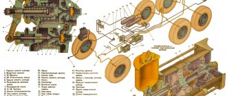
When grooving the brake drum, base it on the inner surfaces of the outer rings of the hub bearings, and the pads as shown in Fig. 5.
Assembling the wheel brake is carried out in the reverse order of disassembly, and it is necessary to fulfill a number of the following mandatory requirements:
- Lubricate the wheel cylinder mirror, piston and sealing lip with brake fluid. Apply graphite lubricant to the pad bushings.
Before connecting the wheel cylinders to the vehicle's hydraulic system, replace the brake fluid and clean the fluid reservoir on the pneumatic boosters from sludge.
Before installing the hub with the brake drum, bring the pads inward using adjusting eccentrics 4 (Fig. 2) and install the axes of the pads in a position in which the installation marks on the ends of the axles are directed backward at the axis of the front pad, and forward at the rear axis.
If during disassembly the position of the axes of the pads on the brake shield is not disturbed, and during reassembly the pads are installed in their places, then the gaps between the pads and the brake drum can be adjusted only with eccentrics 4, turning them (see Fig. 2) until the wheel brakes .
Then turn the eccentric in the opposite direction until the wheel rotates freely (the wheel must be rotated towards the adjustable block).
After adjustment, check the gap through the hatch in the brake drum with a feeler gauge 200 mm long at a distance of 30 mm from the edges of the lining. The gaps should be 0.35 mm at the toe (top of the last) and 0.20 mm at the heel (bottom of the last).
After replacing the brake linings or installing other pad assemblies, as well as if the position of the pad axes on the shields is violated, the gaps should be adjusted with eccentrics 4 and axes 11 of the pads. At the same time, turn the eccentric 4 to slow down the rotation of the wheel.
By turning the axis 11 of the block, determine the direction of its rotation in which the wheel will rotate freely.
Continue rotating the pad axis in the same direction until the wheel is completely braked. Divide the angle of rotation of the block axle from the first braked state of the wheel to the second in half and install the axle in this position.
Repeat this operation several times. Each time the angle of rotation of the block axis from the first braked state of the wheel to the second will decrease. Having completed the adjustment, make a gap of 0.20 mm at the heel of the block, for which insert a 0.20 mm feeler gauge between the drum and the heel of the block and lightly tighten it by turning the axis of the block. In this case, the gap at the toe of the pad should be 0.35 mm. If the clearance at the toe of the pad is different, adjustment should be continued.
After adjusting the brakes of all wheels, install the axle shafts and bleed (fill) the hydraulic system with brake fluid, having first thoroughly cleaned the outer surfaces of the main brake cylinders, brake fluid reservoirs and bypass valves from dirt.
Filling the system with liquid and pumping the brakes is only possible if there is air (7.5 kgf/cm2) in the car’s pneumatic system.
Before filling, thoroughly remove any dirt from the master cylinders and reservoirs. Then, having removed the sealing tubes 1 from both cylinders (Fig. 6) and unscrewing the filler plugs 2, fill the reservoirs with brake fluid. Remove air from the main cylinders through bypass valve 3.
Checking the brake system
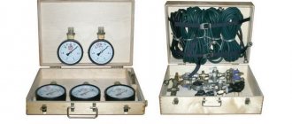
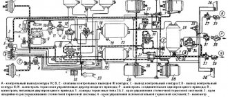
First of all, measure the pressure at the outlet of both sections of the brake valve and test the operation of the triple safety valve (5, see diagram). To do this, connect control pressure gauges to the “brake valve-pneumatic booster” line and, when the pressure is 650-800 kPa (6.5-8.0 kgf/cm²) in the pneumatic system, press the brake pedal all the way. The air pressure on the two-pointer pressure gauge (1) should be the same as in the system. If this is not the case, then you should test the pedal's full travel and free travel, then adjust them.
Diagram of the drive of the working brake system and the combined drive of the trailer brakes
After this, increase the pressure in the system to approximately 800 kPa (8.0 kgf/cm²), until pressure regulator 4 operates, turn off the engine and bleed air from the front axle brake circuit cylinder. When you press the pedal, the pressure on the first control gauge should be equal to the pressure in the system, on the second it should show zero. Then, pressing the brake pedal, lower the pressure to 500 kPa (5.0 kgf/cm²) on the pressure gauge and start the engine. The air pressure should rise at a pressure of 560-600 kPa (5.6-6.0 kgf/cm²) in the front axle brake circuit cylinder. Carry out the same operation with the brake circuit of the middle and rear axles.
First of all, measure the pressure at the outlet of both sections of the brake valve and test the operation of the triple safety valve (5, see diagram). To do this, connect control pressure gauges to the “brake valve-pneumatic booster” line and, when the pressure is 650-800 kPa (6.5-8.0 kgf/cm²) in the pneumatic system, press the brake pedal all the way. The air pressure on the two-pointer pressure gauge (1) should be the same as in the system. If this is not the case, then you should test the pedal's full travel and free travel, then adjust them.
The next step is to check the pressure on the connecting heads (16, 17). To do this, you need to attach a type “B” head (located in the tool kit with a pressure gauge) to the connecting head (18) of “A” type. Compressed air must fill the brake system until the compressor (29) turns off. The control pressure gauge should show a pressure of 500-520 kPa (5.0-5.2 kgf/cm²). Then press the brake pedal or apply the parking brake.
The pressure gauge should read zero. The second step is to check the functioning of the single safety valve. It is necessary to release air from all cylinders (3, 9, 27) and attach a control pressure gauge to the cylinder (9). Then fill the cylinders with compressed air, while comparing the readings of the two-pointer pressure gauge. Compressed air must go into the cylinder (9) after increasing the air pressure to 550 kPa (5.5 kgf/cm²).
Measure the pressure level on the control (16) connection head and the supply (17) two-wire drive: pressure in the supply connection head = air pressure in the system, in the control head = 0. The pressure in the control head must correspond to the pressure in the system when the parking brake system is activated or the brake pedal is pressed.
In order for the pneumatic drive to work well, it is worth draining the condensate regularly from the air cylinders. The operation is carried out only if there is air in the pneumatic system. In winter, it is better to do this by driving the car out of a warm garage. If the temperature is below freezing and the car is parked outside, you need to be more careful when draining the condensate. If it is frozen, you should first defrost these areas with boiling water or steam, but never use open fire. After this, the system is filled to the specified pressure with compressed air.
After adjusting the brakes on all wheels, install the axle shafts and you can fill the hydraulic system with brake fluid. Before doing this, you need to thoroughly clean the external parts of the main brake cylinders, brake fluid tanks and bypass valves from dirt. When you begin assembling the wheel cylinders, you should lubricate the piston as well as the inside of the cylinder with brake fluid. To extend the protection against corrosion of wheel cylinders, apply 5 g of DT-1 lubricant to the cylinder mirror under the wheel caps.
You can pump the brakes and fill the system with fluid only when there is air in the pneumatic system (7.5 kgf/cm2). To fill, it is better to use the liquid indicated in the lubrication card. It is not advisable to mix brake fluids from different manufacturers, because this can cause enlargement of the seals, sediment deposits and, ultimately, brake failure.
Disassembling pneumatic boosters
Drain the brake fluid, unscrew and remove reservoir 4, unscrew the nuts, remove the ties 22 and the rear pneumatic cylinder 19.
Remove the hose, pistons assembled with rod 23, spacer 16 and pusher 8.
Unlock and unscrew the bolts 29, remove the locking plates 30, the front cylinder of the air booster 9 assembled with the cover 31 and the gasket.
Remove the retaining ring 27, washer 28 and remove the piston 6 assembled with the outer seal 7. Remove the ring 33, the inner sealing collar 34 and the spring 36 assembled with the check valve 38.
When disassembling, it is not recommended to unscrew plug 1.
Unscrew the nuts 21 on the rod, remove the pistons 12 assembled, the spacer 16 assembled with the cuff 24 and the sealing rings 17.
Knock pin 26 out of the rod and disconnect rod 23 from pusher 8.
The parts of the main brake cylinder must be washed in alcohol or brake fluid, the parts of the pneumatic booster - in kerosene or gasoline.
Data for monitoring the main dimensions of the parts of the pneumatic booster and the main brake cylinder are given in the table.
Front and rear pneumatic booster cylinders
Brake master cylinder piston
If the cuffs in the spacer, as well as the piston cuffs of the main brake cylinder and the pneumatic booster are worn out or mechanically damaged, replace them. The cylinder mirror must be free of corrosion and marks.
There should be no chips or cracks on the main brake cylinder, and no dents on the air booster cylinders.
Assemble the pneumatic booster in the reverse order of disassembly, and it is necessary to fulfill a number of the following mandatory requirements:
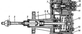
— apply CIATIM-201 lubricant to the working surface of pneumatic cylinders 9, 19 (see Fig. 1), rod 23, cuff 24 and 13. Felt rings of 11 pistons - soak in spindle oil;
Assemble the pneumatic booster pistons in a ring with a diameter of 150 +03 mm;
— when assembling rod 23 with pistons 12, spacer 16 and pusher 8, it is necessary to maintain the dimensions indicated in Fig. 1;
— between the support ring 15 of the cuff and the piston 12, install a rubber sealing ring 25;
— install the gasket and bolts 29 securing the master brake cylinder to the front cylinder of the air booster, as well as nuts 21 securing the pistons to the rod using sealing lubricant;
— install the spacer relative to the front cylinder so that the fittings connecting the outlet holes are on the same straight line;
— install the back cover 20 relative to the front 31 so that the surfaces with holes “B” are in the same plane.
The assembled pneumatic booster must be checked for leaks with an air pressure of 4.0-4.5 kgf/cm 2 . In this case, the main brake cylinder must create a fluid pressure of 100 - 112 kgf/cm2.
Liquid and air leaks are not allowed. Install pneumatic boosters on the car, connect the pipelines and bleed the hydraulic system.
Source
Stages of bleeding the brake system
Bleeding the main brake and wheel cylinders of the service brake system occurs as follows:
- Remove the rubber plug from the master cylinder bypass valve. Pull one end of the tube, which can be found in the tool kit, onto the valve. Immerse the free end of the tube in the brake fluid (it should be poured into a glass container with a volume of more than 0.2 l). The liquid should fill the vessel halfway.
- Unscrew the bypass valve half a turn or 3/4 and press the brake pedal (press quickly and release gradually). This must be done while air comes out of the tube that is in the brake fluid. While pumping, gradually add liquid to the tanks so that no air gets into the system.
- Fully tighten the cylinder bypass valve while pressing down on the pedal.
- Bleed the wheel brake cylinders in a certain order: middle left, rear left, rear right, middle right, front right, front left.
- After filling all the cylinders, add liquid to the tanks so that its level is 1.5-2 cm below the upper limit of the filler neck and tighten the filler plug completely.
Construction and repair of the brake system of the Urals
Ural brakes are designed to smoothly regulate the speed of a truck and make an emergency stop (regardless of the road slope and load). Additional elements of the system ensure that the car is parked. The drive design has connectors designed for connecting pneumatic brake mechanisms of trailers.
Device
The Ural brake system consists of independent systems:
- working, having a combined drive from the pneumatic and hydraulic systems of the truck;
- parking;
- emergency and additional (mining).
The working brake mechanisms of the drum circuit are completely interchangeable. The pneumatic system forms independent circuits for the front brakes, rear bogie and trailer. When you press the pedal located in the cabin, all circuits are turned on. If one line is damaged, then the deceleration is provided by the remaining ones.
The pedal opens the valves in the brake valve, through which the air supply to the pneumatic amplifiers begins. Pressure acts on the pistons, then the force is transmitted to the working elements of the master cylinder, which displaces fluid in the lines. After releasing the pedal, the springs return the pistons to their original position. Additionally, safety and control valves, as well as a force regulator, are installed in the lines.
Compressed air comes from a compressor installed on the engine. The device is equipped with 2 cylinders and operates on the principle of single-stage compression. The compressor head and block are connected to the engine cooling system, lubrication is provided from the main line. Air is taken from the diesel air filter.
The exhaust brake is a damper located in the exhaust gas line.
The device is equipped with a pneumatic drive and is activated by pressing a button in the cabin. When braking, the fuel supply is cut off; a separate actuator is installed for this purpose.
A mechanically operated parking brake acting on a drum mechanism is installed on the transmission. Switching on and off is done using a lever mounted next to the driver's seat. Any of the workers serves as an emergency circuit. If any operating circuit breaks down, the remaining unit provides effective deceleration.
Peculiarities
The Ural brake system is equipped with drum mechanisms that are completely interchangeable. The pneumatic structure itself forms separate brake compartments for different parts of the machine (trailer, front, rear axle). If there is a malfunction in one segment, the remaining analogues in operation are responsible for braking.
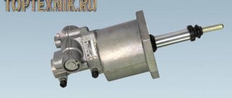
Below is a diagram of the master cylinder with explanations.
- Front pneumatic cylinder.
- Spacer element.
- Radial socket.
- Rear pneumatic cylinder.
- Stock.
- Compression screw.
- Nuts.
- Indicator.
- Main cylinder.
- Cork.
- Brake fluid reservoir.
Malfunctions
Malfunctions of the brake system of the Ural-4320 and similar vehicles:
- slow increase in pressure in receivers due to damage to housings or lines;
- insufficient filling of the circuit cylinders, the cause is breakdown of the control valves or dirt in the lines;
- low pressure in air tanks installed on trailed equipment, the defect is associated with cracks in the parts;
- increased pressure in the receivers, the cause of the breakdown is a failure of the pressure regulator or a malfunction of the control pressure gauge;
- failure of the compression brake indicates problems with the pneumatic valves or a broken valve;
- the ingress of engine oil into the cavities of the pneumatic system indicates wear of the compressor piston group.
If a malfunction occurs in the brake system of a Ural vehicle, further operation is strictly prohibited. The damage must be repaired on site or the vehicle must be towed to the repair area using a rigid hitch.
Brake valve drive
The brake valve drive device with a description of the elements is given below.
- Working pedal.
- Lever arm.
- Adjustment screw.
- Traction fork.
- Fixing nut.
- Drive traction.
- Brake valve lever.
- Bracket.
The safety valve must be adjusted if it does not maintain the pressure in the Ural brake system at the specified positions. Adjustment is carried out by rotating the corresponding screw. In this case, the pressure indicator increases, and after reaching the required parameter, the adjustment bolt is fixed with a nut. To avoid air leakage, the valve is removed, washed and cleaned (in kerosene). Workplaces are washed with soapy water and checked for wear and deformation.
How to bleed and adjust
To make the adjustment you must:
- Turn the eccentrics all the way, with the right part rotating clockwise and the left part counterclockwise. Adjustment of the gap using the pad axis is carried out only in case of wear of the braking surface.
- Loosen the position of the regulators by 30°.
- Check the temperature of the drums while moving. If overheating or insufficient deceleration occurs, readjust the components.
Before bleeding the brake lines, it is necessary to bring the air pressure in the receivers to normal. The surfaces of the cylinders and tanks should be thoroughly wiped from dirt.
To remove air locks from the main and wheel cylinders you need:
- Remove the protective cover installed on the bypass valve fitting. After this, the hose included in the factory tool kit is put on the tube.
- Prepare a clean glass or plastic container that can hold at least 0.3 liters of liquid. Fill the container 1/2 full with brake fluid and lower the free end of the hose into it.
- Unscrew the valve fitting 0.5-0.75 turns, then vigorously press the brake pedal several times, releasing smoothly.
- Manipulations continue until the release of gas bubbles from the tube stops. At the same time, clean liquid is added to the supply tank.
- Depress the brake pedal one last time and hold it in this position. Screw in the fitting and replace the cap.
- By analogy, bleed the wheel cylinders according to the scheme - middle (left), then rear left and right. Then the right middle wheel assembly, right and left front wheels are pumped.
- After removing air from all lines, adjust the fluid level in the supply tank and close the lid.
Repair work
When repairing parts of the Ural brake system, all devices and elements should be carefully removed, washed thoroughly and carefully checked for defects. The assembly is disassembled as follows:
- Using a jack, lift the serviced axle, remove the wheel and hub cover, then unscrew the tire inflation angle by dismantling the axle shaft using a puller.
- Bend down the lock washer and the outer lock, remove the lock and inner washer.
- The brake hub and drum are dismantled along with bearings, locking brackets, and pad springs. The bushing and pad pin are thoroughly cleaned.
- Unscrew the pipeline with bolts, remove the wheel-type cylinder, and remove the block support protrusions.
- Dismantle the brake shield and felt seal.
- When disassembling the main shopping center, do not unscrew the plug.
- It is recommended to disassemble the compressor main unit only if absolutely necessary. It is pressed out using a special puller.
- All oily and contaminated parts of the brake system of the Ural vehicle are washed in gasoline. If the distance from the surface of the linings to the rivet heads is less than 0.5 mm, the parts must be replaced with new modifications.
- The shoe elements of the hand brake are processed together with the expansion cam.
- Drums with ring grooves more than 2 millimeters deep must be machined.
- It would be a good idea to hone wheel cylinders that show signs of corrosion and abrasions. Items showing signs of excessive wear should be replaced.
Source
Bleeding the brake system in a Ural 4320, 5557, 43206 car
If you have to bleed the brakes on a Ural 4320, Ural 43206 or Ural 5557 car, this can only mean one thing - you had a breakdown in the brake system, or you replaced the brake pads due to wear. Regardless of the reasons why you had to start bleeding the brakes yourself, the first thing you need to make sure is the functionality of your car’s braking system.
Bleeding ABS brakes
This procedure is performed to eliminate excess air masses from the hydraulic drive. They could have entered it during repair work or while changing brake fluid.
Air masses inside these mechanisms are unacceptable, since they negatively affect the functioning of the braking system. The need for bleeding can be detected by squeezing the brake pedal several times.
When squeezing the pedal is accompanied by a feeling of excessive smoothness, it is necessary to resume sealing and bleeding the brakes. These procedures can be carried out with the participation of professionals or independently. You need to use exclusively new fluid, and one that is suitable for your car in terms of its performance.
Before pumping, you need to create convenient access to all the necessary components; for this, you may need to remove a certain wheel or drive the car into a special pit.
Pneumohydraulic drive device
The Ural truck uses a mixed type drive, combining the functions of pneumatics and hydraulics - pneumohydraulic, which consists of two working circuits for the front and rear wheels, plus a third circuit responsible for connecting the trailer brakes (single-wire or double-wire drive).
The two main circuits of the Ural braking system have the following components:
- Different air cylinders located parallel to each other.
- A brake valve, the upper section of which belongs to the first circuit, and the lower section to the second.
- Cylinder wheels and general brake booster (pneumatic).
- The second circuit additionally includes a brake force regulator.
Composition of the third circuit:
- Separate air tank.
- Special valves designed to control trailer brakes (separately for single and dual wire actuators).
- Connection heads for each type of drive.
The pneumohydraulic drive of the Urals operates according to the following scheme:
- The compressor, through a pressure regulator, directs compressed air to the safety valves (single and triple).
- The valves distribute the resulting air between all cylinders in each independent circuit.
All circuits are additionally equipped with control outlet valves designed to measure air pressure by connecting a pressure gauge to them. The electrical signal sensor is driven (and some other devices) by air from the main air cylinders, from which the intake is carried out through a triple protection valve.
Ural hand brake
The parking brake mechanism of the Urals (handbrake) is designed for braking the Urals during parking and on slopes (during movement it is used only in emergency cases). The handbrake drive is mechanical, and the lever is located on the side of the driver's seat under the right hand.
The handbrake lever is also connected to the trailer braking lever - when it is raised to the top position, the trailer brakes are also activated.
The operating principle of the Ural manual brake mechanism is as follows:
- When the lever is raised, the force from it, bypassing the intermediate one, is transferred to the release lever.
- From the lever through the rod, the impulse passes to one of the blocks - if the drum rotates counterclockwise, then to the left, while along the way, to the right.
- The block is disconnected from the support pin, pressed against the drum, rotated in the direction of rotation and presses the second block.
Adjusting the pneumatic-hydraulic drive
The pneumatic hydraulic drive of the Urals does not require adjustment and does not require maintenance.
The tightness of a separate pneumatic system is checked by a sharp decrease in pressure on a pressure gauge with two arrows (not lower than 700 kPa), which is located among the driver’s control instruments in the cabin. After stopping the engine (the brake pedal is not pressed), the pressure gauge needles should not twitch much or move noticeably. The same should be observed when the brake pedal is pressed for 20 seconds. At the same time, the tightness of the hydraulic part is assessed.
The functionality of the entire drive is checked by assessing the pressure (650–800 kPa) in all three circuits on pressure gauges connected to the control valves.