The instructions will tell you how to make a digital speedometer for your bike. Yes, it's the same thing we use in cars and motorcycles, but it will be very cheap.
A self-assembled electronic speedometer will have three modes:
- Speedometer (speed detection) and odometer (distance traveled)
- Objective 1 – drive 32 km (20 miles)
- Objective 2 – reach a speed of 30 km/h
The speedometer is built using Arduino, so there is no limit to your imagination.
Tuning techniques
To successfully complete any modification to a car or its dashboard, you need to know a few simple techniques that will allow you to perform the necessary actions. We have already talked about how to properly stick tint film, and these are the same techniques that are used when gluing translucent films to the back of the device display with slots so that the divisions and numbers glow with the right light. Another no less interesting technique is the use of fluorescent paints to paint the needle or scale divisions of the device. To apply this paint evenly, it is enough to use either a simple template over which you can safely paint, or simply carefully apply it with a thin brush. Also, do not forget about the need to correctly calibrate the pointer after removing it, because an incorrectly calibrated device is a very serious problem that can only be solved in a service center.
Wiring
If the speed sensor is working, you need to check the electrical circuit from the EMF to the ECU.
- Disconnect both plugs.
- Set the tester to audio dialing mode.
- Test all 3 wires one by one, inserting the probes of the measuring device strictly from both ends of the wiring.
An audible alarm from each wire will indicate the integrity of the line.
Self-installation
If a previously installed electric speedometer has become unusable, you can connect it yourself without any problems. The main task during installation is to correctly align the electrical wiring socket. On all modern cars, the pinout is as follows:
- "1" pin is the incoming "+" power supply.
- “2” contact outputs an impulse to the control unit.
- "3" pin is the incoming "-" power supply.
It is also possible to replace a mechanical speedometer with an electronic one for cars that are not equipped with an on-board computer. To do this, you need a universal speedometer that works without an ECU. For installation, you will need to select a speed sensor that is suitable for mounting the mechanical cable drive. The new sensor must have a contact rod of the required length to respond to the rotation of the transmission secondary shaft. The main problem with the conversion is choosing the right speed sensor. For domestic cars it should be 6 pulse.
GPS module NEO6M
NEO-6M is a popular GPS receiver with a built-in ceramic antenna that provides good signal reception from GPS satellites. This receiver is capable of tracking up to 22 satellites and provides location determination anywhere in the world. The module has a backup battery, which allows it to save data when the main power supply to the circuit is turned off.
The core of the module is the NEO-6M GPS chip from u-blox. It can track up to 22 satellites over 50 channels and has extremely good sensitivity (-161 dBm). The module supports data transfer rates of 4800-230400 baud. By default it is set to 9600 baud.
Module specifications:
- operating voltage: 2.7-3.6V DC (direct current);
- operating current: 67 mA;
- baud rate: 4800-230400 (9600 default);
- communication protocol: NEMA;
- interface: UART;
- external antenna and built-in non-volatile memory (EEPROM).
Assignment of contacts (pinout) of the NEO6M GPS module: • VCC: input supply voltage; • GND: common contact (ground); • RX, TX: pins for UART (serial) communication with the microcontroller.
On our website we have already quite often reviewed projects using GPS modules; a list of these projects can be viewed at the following link.
Basic faults
The electronic speed meter is a fairly reliable device. But it also often fails. The malfunctions are as follows:
- Dirt or liquid on the contacts interrupts the electrical circuit of the entire speed counting system.
- Failure of the speedometer drive.
- Violation of the integrity of the wiring from the sensor to the ECU.
- Malfunction of the fuse that protects the speedometer from voltage surges and short circuits.
- Loss of "0" contact.
- An error appears in the on-board computer itself.
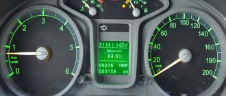
The driver will be notified by the dashboard if there is a malfunction in the electronic device system. The computer will give an error.
The “Check Engine” sign should also light up (in the Russian version, the output is possible - Engine check required), since the system includes fuel supply sensors.
Device
An electronic speedometer for a car is a simple design. Now the speed sensor, which has replaced the cable drive, is responsible for its readings. The device consists of the following elements:
- The speed meter itself, equipped with an electric motor or contact relay.
- Electrical wiring for power supply and transmission of impulses from the electronic control unit (ECU).
- Speedometer drive or speed sensor.
On cars of different brands, this system is supplemented by various other sensors that are not related to speed calculation, but are built into the circuit.
Speed sensor
EMF is the main part that is responsible for supplying electronic pulses. You will need a tester to check. Next you need:
- Remove the plug from the EMF socket.
- Clean both connections from dust and dirt.
- Raise the right driving wheel of the car on a jack.
- Start the engine and engage 1st gear.
- Set the tester to DC voltage measurement mode up to 12 volts.
- Insert the “+” control probe of the tester into the “2” connector of the sensor socket.
- “-” connect the tester control probe to the engine body.
The tester should show results within 9 volts. When you press the gas pedal, these indicators should change. The absence of readings is a consequence of a malfunction of the speed sensor.
Speedometer
The speedometer itself is checked via the EMF connector.
- Disconnect the sensor plug.
- Route the wire from the “+” terminal of the battery.
- Lightly touch the “2” terminal of the plug with the other end of the wire.
In this way impulses are simulated. If the speedometer is working properly, its needle should respond to touching the terminal.
OLED display
The term OLED stands for “Organic Light emitting diode” and the OLED display we use uses the same technology as the modern TVs we are used to, only the screen resolution of our display is significantly lower than that of TVs. With such displays, Arduino projects immediately begin to “sparkle with new colors” since they provide a much more presentable picture than conventional monochrome LCD displays. In our project we will use a monochrome OLED display SH1106 1.28” with 4 pins, connected via the I2C interface.
Display Specifications:
- driver chip: SH1106;
- input voltage: 3.3V-5V DC;
- resolution: 128×64;
- interface: I2C;
- current consumption: 8 mA;
- pixel color: blue;
- viewing angle: >160 degrees.
Assignment of contacts (pinout) of the display: VCC: supply voltage 3.3-5V DC; GND: common wire (ground); SCL: I2C interface clock pin; SDA: I2C interface data pin.
The Arduino community has already developed quite a lot of libraries for working with OLED displays, among them we liked the Adafruit_SH1106.h library - it is easy to use and allows you to work with graphics.
We have previously used a similar display in the following projects:
- connecting the SSD1306 display to the Arduino board;
- smart watches on Arduino and OLED display;
- non-contact thermometer based on Arduino and temperature sensor MLX90614;
- automatic air conditioner temperature control using Arduino.
Symptoms of a problem
Malfunctions of the electronic speedometer are immediately noticeable. You can recognize them by the following signs:
- The complete lack of functionality of the scoreboard and its illumination. The cause may be a blown fuse.
- The arrow does not move on the scoreboard. The cause may be a malfunctioning speed sensor or a break in the electrical circuit.
- The arrow jumps indicate problems with the sensor or poor contact in the circuit.
- Poor acceleration of the car, irregular speed when changing gears, increased fuel consumption will indicate problems with the electronic speed sensor (EMS).
If such problems occur, it is necessary to promptly check all elements of the electronic speedometer.
Adjusting the brightness of the backlight
Most often, to adjust the brightness of the backlight located behind the device, you need to assemble it, but if something does not suit the brightness, the device will need to be disassembled and adjusted again. In order to avoid wasting time on such actions, we advise you to connect the backlight through a variable rheostat, which can be used to control the intensity of the glow by simply turning it up. Naturally, it is best to carry out the adjustment 3 times - during the day, at dusk and at night, to understand whether it is convenient to look at the devices.