Does the Ural 4320 make a lot of noise while driving? These signs are for 100% disassembly and adjustment of the Ural gearbox. The cause-and-effect series is varied:
- distortion of the contact patch at the points of engagement of bevel gears, which was preceded by a violation of the adjustment process of bevel bearings;
- wear and tear of bearings and chipping of gear teeth;
- Inadmissible oil level in the axle housing.
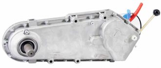
Front axle gearbox Ural 4320
Dismantling process
When repairing components of the Ural 4320, you should take into account: removing the front axle gearbox differs from the rear axle in that it is removed from the vehicle upon completion of dismantling.
After dismantling and installation on stands, the Ural gearbox is removed in the following way:
- disconnect the brake hoses, steering linkage rod, elements of the sealing device;
- unscrew the nuts connecting the ball joints;
- a mounting blade will help in dismantling the steering knuckle assemblies;
- We remove the entire side cover of the gearbox housing with an oil supply type fitting;
- unscrew the bolts and nuts holding the crankcase together with two bolts located inside;
- Using a device for lifting the load, we remove the unit itself from the axle housing.
The Ural rear axle gearbox is dismantled directly on the vehicle:
- Ural 4320 is installed on an inspection ditch. First, close the wheel valves by disconnecting their hoses supplying air, and remove the protective casings. Then drain the oil from the crankcase.
- We unscrew the bolts holding the tops of the hubs together, remove the angles that supply air from the axle shafts; and remove the tops of the hubs in parallel with the hoses and seals. Using a puller, remove the axle shafts.
- We remove the propeller shaft 4320 of the rear axle drive by disconnecting and moving to the side: the reaction rod, its upper bracket, pipelines, hoses of the braking and sealed system. We remove the side cover of the unit together with the oil supply fitting, unscrew the bolts and nuts located in the middle of the crankcase. We remove the gearbox from the crankcase.
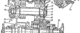
Details of the front axle gearbox Ural 4320
TRUCKS GAZ, ZIL, KAMAZ, URAL, MAZ, KRAZ
_________________________________________________________________________________________
Construction and adjustment of Ural-4320 bridges
Drive axles Ural-4320, Ural-5557 Drive axles of the Ural-4320, 5557 car are of the through type, with an overhead final drive.
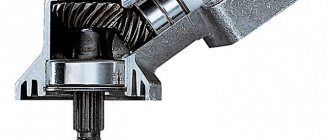
Rice. 27. Main gear of the drive axle gearbox Ural-4320, 5557 1-bevel driven gear; 2.23-cylindrical roller bearings; 3-main gear housing; 4-gear cylindrical drive; 5-cup bearings; 6-taper roller bearing; 7,8,12-adjusting gaskets; 9-bearing cup cover; 10-flange of the middle axle drive; 11-cuff; 13-cup bearings of the drive bevel gear; 14-bevel drive gear; 15-breather; 16-drive gear shaft; 17-gasket; 18-flange for rear axle drive; 19-flange nut; 20-rear bearing cover; 21-spacer sleeve; 22-front bearing cover; 24-adjusting washer; 25-nut; 26-lock washer; 27-lock washer; 28-lock nut; 29-semi-axial gear; 30- differential satellite; 31-differential crosspiece; 32-gear driven cylindrical; 33-support washer; 34-differential bearing cover; 35-locking plate; 36-key plate; 37-nut adjusting differential bearing; 38-cup differential; 39- crankcase cover; I-for the front axle; II-for the rear axle The main gear of the Ural-4320, 5557 bridge is double, consists of a pair of bevel gears 1 and 14 (Fig. 27) with spiral teeth and a pair of spur gears 4 and 32 with oblique teeth. A symmetrical bevel differential with four pinions is bolted to the driven spur gear. Depending on the technical requirements for the Ural-4320, 5557 vehicle, the main gears have gear ratios of 7.32; 6.7; 8.9 and 8.05. To distinguish the main gears of the Ural-4320, 5557, they are marked with plates indicating the gear ratio, installed under the bolt securing the bearing cup cover of the drive spur gear. Final drives with a gear ratio of 8.9 do not have marking plates. The gears of the main cylindrical gears of the Ural-4320, 5557 axle reducer are distinguished by marks on the drive and driven gears.
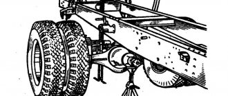
Rice. 28. Middle (rear) driving axle Ural-4320, 5557 1-air supply cuffs; 2-cylinder wheel; 3-drum brake; 4-shaft; 5-support spring bracket; 6-crankcase cover; 7.9-gaskets; 8th gear main; 10-axle housing; 11-drain plug; 12-control plug; 13-axle housing The main gear of the drive axle gearbox of Ural-4320, 5557 vehicles is installed on the axle housing 10 (Fig. 28) through a 0.8 mm thick paronite gasket 9 and secured with thirteen bolts and two studs. Eleven bolts and studs are installed externally, and two bolts are installed in the bevel gear cavity. Access to the internal bolts is possible only after removing the side cover 6. Spring washers are installed under the external bolts and nuts of the studs. The internal bolts are secured with wire. The gears and bearings of the main gear of the Ural-4320, 5557 axle gearbox are lubricated with oil poured into the axle housing and the main gear housing to the level of the control hole. The oil is picked up by the gears, splashed and through roller bearing 2 (see Fig. 27) enters the cavity of the bevel gears of the main gear housing, from where it flows into the axle housing. The bearings of the drive bevel gear are lubricated with oil from the cavity of the bevel gears, which is fed into the bearing cup through a pocket on the crankcase cover and the oil supply fitting. The main gears of the front and rear axles of the Ural-4320, 5557 differ from the main gear of the middle axle by drive flanges. A bushing 21 with a cover 22 is installed on the front end of the drive gear shaft of the front axle Ural-4320, and a flange 18 is installed on the rear end. The main gear of the rear axle gearbox Ural-4320, 5557 has one flange on the side of the drive bevel gear. The opposite end of the drive gear shaft may not have splines. Crankcases 10 (see Fig. 28) of the axles are combined, consisting of a cast middle part and tubular axle housings pressed into it. The axle shafts of the drive axles of the Ural-4320, 5557 vehicles are completely unloaded, the connection of the axle shaft to the hub is splined. Front axle of the car Ural-4320, Ural-5557 Front axle of the car Ural-4320, 5557 driving, steered. The design of the drive to the steered wheels of the front drive axle Ural-4320 is shown in Fig. 29.
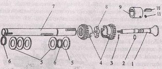
Rice. 29. Drive to the steered wheels of the front drive axle of the Ural-4320, 5557 1-air supply hose; 2-lock washer; 3-lock washer; 4-lock nut; 5-wheel bearing nut; 6-trunnion; heptagonal air supply; 8-wheel hub cover; 9-axle outer; 10-block cuffs; 11,17,19-sealing gaskets; 12-bearing; 13-hub; 14-cylinder wheel brake; 15-drum brake; 16-brake caliper; 18-ball joint; 20-axle shaft internal; 21-axle housing; 22-knuckle joint; 23-disc hinge; 24-fork of the outer axle shaft; 25-pin; 26-reflector; 27-cuff Torque on the front drive wheels of the Ural-4320, 5557 vehicle is transmitted through axle shafts and constant velocity joints (Fig. 30).
Rice. 30. Constant velocity joint (CV joint) Ural-4320, 5557 1-fork; 2-fist; 3-disc; 4-axle internal In the drive to the front drive wheels of the car, a cam joint of constant angular speeds (CV joint) is used. The CV joint of the Ural-4320, 5557 car consists of two forks, two knuckles and a disk. Steering knuckles Ural-4320, 5557 have machined cylindrical journals and internal grooves with flat side surfaces. The cylindrical journals of the knuckles of the front axle Ural-4320, 5557 are covered by forks, and the disk enters the grooves. Thanks to this connection, each of the shafts is able to rotate relative to the axis of the disk and relative to the necks of the fists, i.e., in two mutually perpendicular directions, similar to what happens in a cardan joint of unequal angular velocities. Thus, the cam joint of the CV joint consists of two hinges of unequal angular velocities, due to which the axle shaft and the wheel drive shaft - the outer axle shaft with the flange rotate with the same angular velocities. The necessary accuracy of installation of the universal joint Ural-4320, 5557 relative to the kingpin axis is ensured by the centering bushings of the forks and support washers placed in the ball joint and the pivot pin. Due to the large contact surface of the parts through which forces are transmitted, the cam joint has a relatively small size. For reliable and durable operation of the Ural-4320, 5557 drive axles, use oils according to the lubricants and working fluids chart and maintain the required level in the crankcases. To change the lubricant in the hinges of the front axle axle shafts, remove the wheel, brake drum with hub, caliper, and steering axle. Remove grease and wash the constant velocity joint parts. If it is necessary to dismantle the ball joint from the housing of the front axle Ural-4320, 5557, use the puller bolts located in the large tool bag. To do this, install them in the threaded holes of the ball joint flange and, turning them evenly, remove the tail of the ball joint from engagement with the axle housing. Regularly check the tightening of the bolts securing the main gear to the housing of the Ural-4320 axle. Loosening the bolts causes the crankcase to bend. When adjusting the main gear of the Ural-4320, 5557 gearbox, adjust the preload of the tapered bearings and check the contact patch in the engagement of the bevel pair of gears of the main gear. Perform adjustment work with the main gear removed from the vehicle. Control the amount of tension by the torque required to rotate the shaft. Determine the moment of resistance to rotation using a dynamometer. It is necessary to measure the torque on the shaft while turning it smoothly in one direction and after at least five full revolutions. It should be borne in mind that incorrect adjustment of the bearings of the Ural-4320 drive axles can lead to the destruction of not only the bearings themselves, but also the final drive gears. Adjustment of the main gear of the drive axle Ural-4320, 5557 is carried out in the following sequence: Install the main gear of the Ural-4320, 5557 into the device, remove the differential and flanges. Unscrew the bolts securing the bearing housing of the drive bevel gear. Remove the drive gear shaft with the cup and gear. Install the drive gear in a vise, holding it by the ring gear. Unscrew the cover bolts and remove it. Unlock the locknut and unscrew it. Remove the lock and lock washers. Tighten the nut to a torque of 450-500 Nm (45-50 kg/cm). Install the indicator device and determine the clearance in the bearings. If there is no gap after tightening the nut, there is no need to adjust the cup bearings. Calculate the amount of reduction in the thickness of the adjusting washer 24 (see Fig. 27) (the amount of the gap plus 0.03-0.05 mm of preload). Unscrew the nut, remove the bearing and adjusting washer. Grind (or size) the washer to the required size, install the washer and assemble the drive bevel gear bearing assembly. The tightening torque of the nuts is 450-500 Nm (45-50 kg/cm). Lock the locknut by bending the washer onto one of the edges. The torque required to rotate the drive bevel gear in the bearings should be 0.6-1.4 Nm (0.06-0.14 kg/cm). The force on the dynamometer when unwinding the cord from the surface of the glass is 7.5-17.5 N (0.75-1.75 kgf). Adjust the preload of the spur gear bearings. Adjust the bearings by selecting the gasket package 8 (see Fig. 27) under the cover 9 of the cup 5. The torque required to rotate the intermediate shaft should be 0.9-1.5 Nm (0.09-0.15 kg/cm) . When measuring torque using a dynamometer, wrap the cord around the spur gear ring; Final drive ratio / Dynamometer readings, N (kgf): 6.7 / 16.5-27.6 (1.65-2.76) 7.32 / 17.6-29.3 (1.76-2 .93) 8.05 / 18.8-31.3 (1.88-3.13) 8.9 / 20-33.4 (2.0-3.34) Please note that with the removal of gaskets from under the cup cover, when adjusting the bearings, the driven bevel gear Ural-4320, 5557 shifts towards decreasing the side clearance, therefore, to maintain the clearance under the cup 5 bearings, install additional spacers. Install the cup with the drive bevel gear into the main gear housing Ural-4320, 5557. Tighten the cup fastening bolts to a torque of 60-80 N (6-8 kgf). Check that the bevel gears engage the paint correctly. The length of the impression must be at least 60% of the length of the tooth. The imprint should be located no closer than 5 mm to the edges of the tooth. In this case, the lateral gap in the teeth (at the wide part) should be 0.1-0.4 mm. To change the backlash of bevel gears without distorting the contact, move both gears a distance proportional to the number of teeth on each gear, i.e. move the driven bevel gear 2.2 times (24:11) further than the drive gear. Install the Ural-4320, 5557 differential and adjust the differential bearings. Tighten the differential bearing cap bolts to a torque of 250-320 Nm (25-32 kg/cm). Adjust the differential bearings Ural-4320, 5557 with nuts 37 (see Fig. 27). After tightening the nuts, the distance between the differential bearing caps should increase by 0.04-0.14 mm. During adjustment, rotate the differential to install the rollers in the bearings. The crown of the driven spur gear must be positioned symmetrically relative to the crown of the drive gear. In connection with the improvement of the manufacturing technology of differential gears, the tooth profile of the side gears and satellites has changed. Modified gears are not interchangeable with previously produced ones and should only be replaced as a complete set. For distinction, marks have been introduced on the side of the small module: on the axle gear there is a groove with a diameter of 90 mm and on the satellite there is a stepped end. When assembling the main gear of the Ural-4320, 5557 bridge reducer, install the inner ring and roller bearing cage 2 of the driven bevel gear as shown in Fig. 27. Adjustment of the bearings of the steering knuckle pins of the front axle Ural-4320 is carried out in the following order: Remove the wheels and install stops under the lower covers of the steering knuckles; Remove the left steering knuckle lever and the upper cover of the right steering knuckle Ural-4320. Remove two gaskets from the pack of gaskets under the lever and the cover: one with a thickness of 0.05 mm, the other with a thickness of 0.1 mm; put 50 g of lubricant into the cavity of the lever and the cover and install the lever and cover in place; tighten the nuts to a torque of 160-280 Nm (16-28 kg/cm); Remove the stops and remove the bottom covers; Remove a 0.15 mm thick [(0.05+0.1) mm] pack of gaskets from under each cover; Install the covers and tighten the nuts to a torque of 160-280 Nm (16-28 kg/cm); Install the wheels. Adjusting the wheel hub bearings of the driving axles Ural-4320, 5557 Raise the axle from the side of the adjustable wheel with a jack; Remove the cover; Using a puller, remove the axle shaft splines from engagement with the hub and remove the axle shaft; Unscrew the outer nut and remove the lock and lock washers; Rotating the wheel by hand, make sure that there is no friction between the Ural-4320, 5557 brake drum and the pads; Tighten the nut to a torque of 200-250 Nm (20-25 kg/cm); When tightening the nut, turn the hub to self-install the rollers in the bearings, then loosen the nut by about 1/5-1/6 of a turn. Install the lock washer. If the nut pin does not coincide with the holes of the lock washer, it is allowed to loosen the nut by an amount not exceeding the distance between two adjacent holes. Install the lock washer, tighten the locknut to a torque of 400-500 Nm (40-50 kg/cm) and lock it. To ensure the connection of the wheel inflation hose to the wheel crane of the Ural-4320 vehicle, install the axle shaft with the hub cover so that the inflation hose is located in the direction of the wheel crane symmetrically between the wheel mounting studs. After completing assembly, check the adjustment of the wheel bearings during a run of 10-20 km. When adjusted correctly, the Ural-4320, 5557 wheel hub should be cold or slightly heated. If the hub heats up noticeably to the touch, check the bearing adjustment.
_________________________________________________________________________________________
- GAZ-3307 clutch maintenance
- Steering system GAZ-3307
- Gearbox parts for GAZ-3307
- Maintenance of the rear axle GAZ-3307
- Maintenance of the fuel system of the D-245 diesel engine
- Clutch GAZ-3309 with a diesel engine
- Operations for disassembling the GAZ-3309 gearbox
- GAZ-3309 front axle service
- Repair of cardan shafts of GAZ-3309 cars
_________________________________________________________________________________________
_________________________________________________________________________________________
- Operations for assembling basic components of the ZIL-130 engine
- Service and repair operations for the ZIL-130 gearbox
- Maintenance and repair of ZIL-130 clutch
- Repair and adjustment of the rear axle ZIL-130
_________________________________________________________________________________________
- KAMAZ-4310, 43118, 43114
- KAMAZ-5320, 55111, 53212, 5511, 55102
- KAMAZ-65115, 6520, 65117
- KAMAZ-4308
- Engine KAMAZ-740
_________________________________________________________________________________________
- Parts of the cylinder block and head of the YaMZ-236 engine
- Service maintenance of the YaMZ-236 piston group and crankshaft
- Diagnostics and technical adjustments of the YaMZ-236 engine
- Design and adjustment of fuel injection pump and injectors of the YaMZ-236 engine
- Cylinder block and piston YaMZ-238
- Components of the YaMZ-238 diesel fuel supply system
- Design and adjustment of the fuel injection pump of the YaMZ-238 diesel engine
- Technical design of the YaMZ-239 gearbox
_________________________________________________________________________________________
- Components of the front axle and steering rods of the Maz-5516, 5440
- Steering system of Maz-5516, 5440 cars
- Clutch and gearbox parts Maz-5516, 5440
- Maintenance of drive axles of MAZ-5516, 5440 vehicles
- Power steering for Maz-5551, 5335 cars
- Maintenance of cardan transmission of Maz-5551, 5335 cars
- Maintenance and adjustment of clutch MAZ-5551, 5335
- Repair and service of the rear axle of MAZ-5551, 5335 cars
_________________________________________________________________________________________
- Gearbox Ural-4320
- Construction and adjustment of Ural-4320 bridges
- Maintenance of transfer case Ural-4320
- Steering components Ural-4320
_________________________________________________________________________________________
- Servicing the KRAZ-255, 260 gearbox
- Steering mechanism and power steering Kraz-255, 260
- Adjustments and repairs of the power steering cylinder and steering rods of the Kraz car
- Drive axle components and drive shafts Kraz-255, 260
Disassembly
To disassemble the gearbox 4320 of the front or rear axles, similar manipulations are carried out, namely:
- The bolts are unscrewed, the lock washers and locking plates are bent. The differential bearing caps are removed. Be sure to mark them with paint to avoid depersonalizing the lids.
- Before removing the differential, remove the adjusting nuts with the outer rings of the bearings.
- We fix the structure - this will allow us to unpin and unscrew the nut connecting the flange of the drive bevel gear shaft. This makes the flange accessible for removal.
- Having unscrewed the bolts that hold the structure, we remove the cover with the sealing collar. In the bearing housing, we pay attention to the bolts, and in the crankcase of the unit, the following should be removed: the shaft, a pack of adjusting type gaskets, the inner ring of the rear bearing and the drive bevel gear. The bearing cup is ready for the pack of adjusting shims to be released from it and the bridge sealing plug to be unscrewed.
- We unscrew the bolts that connect the bearing cup cover to the drive type spur gear. Now it is possible to dismantle the cover in parallel with the gasket package of an adjusting nature. Before removing the washer, we smooth it out and unscrew the bolts that secure it. Using special threaded holes in the flange, we squeeze out a glass with tapered bearings and a package of adjusting gaskets. We fix the latter on the cover and the bearing cup. The driven bevel gear assembly is removed through the 4320 gearbox housing window.
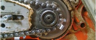
Features of damage, diagnostics, repair of gearboxes of the URAL 4320 truck
Civilian and military modifications of the URAL 4320 truck are equipped with all-wheel drive. To ensure the operation of the all-wheel drive transmission, separate gearboxes are installed on the three axles of the truck. During extreme off-road use of a truck, breakdowns and misalignment of the gearbox become a frequent malfunction. In the initial stage, the malfunction manifests itself:
- unnatural noises (humming, howling, metallic knocking, crunching);
- crankcase overheating;
- oil leaks.
If the gearbox is not repaired, the following stages of failure cause destruction of the differential housing and separation of the axle shafts.
The causes of failure are:
- natural wear of gearbox parts;
- oil starvation of gears (lack of transmission fluid in the crankcase);
- broken gear meshing adjustments;
- broken bearings;
- mechanical damage to gears (chips, scuffing, pitting of teeth).
You can independently determine the initial malfunctions of the gearbox when the engine is revved up while the truck is stationary (without engaging the gear), or while driving in neutral gear with the engine turned off. The absence or increase in noise indicates a malfunction of the mechanism. Accurate diagnostics and identification of repair areas can only be carried out with complete disassembly of the gearbox.
Assembly and adjustment
General assembly of the unit involves performing preliminary manipulations: assembly of components, lubrication of seals, thread surfaces and sealing plugs, welding surfaces of covers and gearbox housing; lubrication of bearings with transmission oil, and the working edges of the sealing collars with lubricant.
The installation process is a dismantling operation in reverse order, which requires:
- Checking the adjustment indicators of the bearing preload by selecting the diameter of the adjusting type shim pack.
- Measuring the amount of torque under the condition of continuous uniform rotation of the driven bevel gear assembly. Condition: manipulation is carried out no earlier than after five full revolutions.
Checking the performance of the gearbox, adjusting the mechanism
Before assembling the mechanism and installing the covers, the contact pattern on the bevel gears is checked. When checking, the teeth of the driven gear are painted with red and yellow paint from an aerosol can. After this, the drive gear flange is rotated in different directions. To obtain a clear imprint, the driven gear is braked.
Incorrect adjustment shifts the contact patch towards the top, narrow end, or base of the tooth. To eliminate deficiencies, the gears are moved or moved back, the side clearances are changed using adjusting nuts, and adjusting rings of reduced or increased thickness are used.
During assembly (carried out in the reverse order), Nigrol (TAD-17 lubricant) lubricates the seals, bearings, threaded connections, sealing plugs, and the edges of the cuffs. Bolts, nuts, cotter pins, gaskets, and studs are completely replaced. Transmission fluid is poured into the crankcase (according to standards).
After repair and adjustment, the gearbox torque is measured on the test bench. Mandatory conditions are uniform movement of the shaft, turning on the measuring device after 5-10 full revolutions of the gears. The correct assembly and adjustment is evidenced by the almost silent operation of the gearbox and the standard torque indicators.