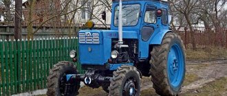
The T-16 self-propelled tractor chassis is one example of a vehicle that has received wider use than the developers originally planned.
This tractor was produced from 1961 to 1967 for agricultural work. Its main functions were spraying, plowing the soil, cultivating crops, hilling, weed control, and harvesting.
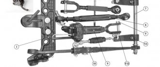
For greater functionality, the SS had front mounts for installing a variety of additional equipment - cultivators, sprayers, row-crop and harvesting machines, saws, grader shovels, etc. All of them were driven by a power take-off shaft, that is, by transmitting torque from the tractor to the attachment. This means that the vehicle was developed as a powerful vehicle with high cross-country ability and reliability.
That is why the tractor was able to find application in other areas of the economy - it was actively used in construction to deliver building materials and drive construction mechanisms. In fact, the relatively small, compact T-16 was able to do the work of a truck, while its maneuverability and functionality were much higher.
Even half a century after the end of production of the T-16, the vehicles continue to serve and be modernized. The self-propelled chassis has become a rarity, and experts consider it a symbol of a high-quality, multi-purpose vehicle.
Tractor T-16 with modern tuning
Specifications
The T-16 tractor has become in demand and indispensable due to its technical characteristics, although they cannot be called outstanding.
- The engine had a power of only 16 horsepower.
- Weight was 1685 kg.
- Number of gears – 8 (7 forward and 1 reverse).
- Fuel consumption is relatively low - 274 g/kWh.
- The speed ranged from 1.5 km/h to 17 km/h.
- Rated speed – 1750 rpm.
- Cylinder diameter - 95 mm.
- The piston stroke is 120 mm.
- Traction class – First (up to 0.6 tons).
- The platform's load capacity is up to 750 kg.
The ability to move steadily at low speeds has become the main technical advantage of the tractor; this is very important in construction and agriculture. Where other vehicles could not cope, the M 16 came to the rescue.
Engine
The tractor engine is marked D16; it is a two-cylinder, four-stroke, diesel engine.
Since some of the heat from the burning fuel was not used for useful work, it was transferred to adjacent engine parts, causing an undesirable increase in temperature. Therefore, an air cooling system with a fan was developed to remove heat from parts that come into contact with hot gases. This made it possible to maintain the temperature within acceptable limits.
As for the operation of the SS in cold conditions, sometimes it happened that the engine did not start, since the design did not provide a pre-heater. Over time, a device was developed to facilitate engine starting at low temperatures (a manual starting pump on the intake manifold).
Engine D16
Tractor fuel consumption
Fuel consumption for this engine can be considered ideally low, because there is a special device that immediately supplies both heated steam and diesel fuel to form a mixture (pre-chamber mixture formation).
Partial combustion of fuel occurs in the prechamber. With high-quality mixture formation in pre-chamber engines, the combustion process takes place with excess air, which reduces fuel consumption.
Transmission
The self-propelled chassis has an eight-speed gearbox - seven front and one rear.
The gear shift circuit is configured so that the locking mechanism prevents spontaneous gear shifting when the clutch is not disengaged.
The power take-off shaft is semi-independent, located on the left side of the housing, its rotation speed is 530 rpm. The clutch drives the shaft, which in turn rotates the power take-off shaft.
Hydraulic system
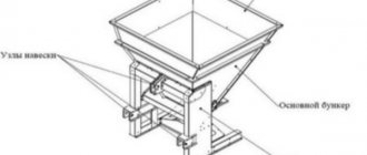
When developing the chassis, it was assumed that the vehicle would interact (aggregate) with various suspended hydraulic equipment. Therefore, the T-16 design is equipped with a separate hydraulic unit system, which includes:
- hydraulic pump;
- hydraulic distributor;
- a pair of hydraulic cylinders;
- oil tank and oil lines.
This equipment allows you to perform a wide range of agricultural and municipal work.
Steering
The T-16 can be controlled either mechanically or using a hydraulic booster.
Mechanical steering involves the front wheels rotating from the steering wheel through a system of driveshafts and gears.
Power steering changes the pattern: first, the force is transmitted to the dispenser shank, which regulates and directs the flow of fluid into the cavity of the hydraulic cylinder. Under the action of the pump, the fluid moves, and the swing arm transmits force to the front wheels.
Chassis system
The chassis chassis standard includes front and rear axles, frame and wheels.
The characteristic feature of the SSh T-16 chassis is that the frame is designed for the installation of additional equipment - a body or attachments.
The frame has a strong welded structure and consists of two longitudinal and two transverse beams. Two bushings are mounted into the front beam to provide rolling support for the axle.
The rear axle is a drive axle; powerful wheels made of a profiled rim are attached to it, with racks welded along the inner diameter of which to install the disc.
The installation of wheels is complemented by low-pressure tires. It is important to monitor the location of the guide arrows on the tire tread during installation. For proper traction between the wheels and the surface, the guides must point forward.
The front axle has a simple design: a balancer and two steering knuckles. They are the base for the hub on which the wheel is mounted.
dimensions
The dimensions of the M 16 are relatively small; the longitudinal base of the self-propelled chassis is 2.5 m, which makes it maneuverable in rooms and confined spaces. The tight turning radius also contributes to off-road performance and mobility in a variety of conditions.
| Dimensions | Meaning |
| Length | 3.8 m |
| Width | 2 m |
| Height | 2.6 m |
| Weight | 1,685 kg |
Transmission
It is typical for a tractor transmission that torque is transmitted from the engine to the wheels, and then to all active mechanisms of the attached equipment. This is the so-called stepped manual transmission.
Transmission maintenance involves ensuring normal clutch operation, monitoring the condition of the connections and adjusting them.
It is important to follow the rules that ensure proper operation of the transmission; they are universal: 1. You cannot keep the clutch pedal depressed while driving. 2. Do not disengage the clutch while the engine is running. 3. The clutch is engaged smoothly, without jerking.
Checking for clutch slippage or incomplete disengagement helps determine where transmission adjustments are needed.
The T-16 chassis is equipped with two dry band brakes, which allow you to reduce speed, hold the machine while working, move safely downhill, and stop movement. Dual braking is achieved through steering and braking of one drive wheel. This increases the maneuverability of the machine.
Electrical equipment
The self-propelled chassis is equipped with electrical equipment, which is designed to start the engine, power electrical appliances and devices, and ensure operation at night.
All devices are connected to each other using a single-wire circuit, in which the metal parts of the chassis serve as the negative wire. The rated voltage in the system is within 12 V.
Main electrical equipment:
| DC generator | T-80V |
| Relay regulator | RR-81D |
| Accumulator battery | R-ST-68-EM |
| Headlights | FG-300 |
| Sound signal | S-56-G |
| Ammeter | AP6-E |
| Starter | ST-204 |
The T-16 lacks a windshield wiper, oil temperature regulator, and voltage regulator; they appeared later in the T-16M and T-16MG modifications.
Electrical equipment requires careful attention to insulation and fastening. To protect against damage, the wires are collected in separate bundles, but sometimes they can touch the chassis ground, causing a short circuit. To avoid this, it is necessary to check the condition and insulation of the wires during operation and eliminate risks.
Section II. WHEEL TRACTORS
SELF-PROPELLED CHASSIS T-16Electrical equipment
self-propelled chassis T-16 includes a generator, a relay regulator and a battery with a ground switch, an electric starter and a heating coil with a headlight switch button, a rear light with bulbs and a brake light switch 12 and a tail light 14, a sound signal / with a power button 13, headlight switch 15, ammeter 17, fuse block 18 and power socket 16.
Electrical equipment
Diagnostics of electrical equipment of cars
A.G. Sergeev, V.E ...
| System Diagnostic Parameters electrical equipment of cars . RELATIONSHIP OF STRUCTURAL AND OUTPUT PARAMETERS OF ELECTRICAL EQUIPMENT ... www.bibliotekar.ru/auto-elektrooborudovanie/ |
Comprehensive diagnostics of vehicle electrical equipment
…
| Universal diagnostic tools car electrical equipment can be classified: by type—portable, mobile and stationary; … bibliotekar.ru/auto-elektrooborudovanie/11.htm |
Electrical equipment
.
cars
have a 24-volt system...
| Cars MAZs have a 24-volt |
Power supply system. Methods and means of diagnosis...
| Diagnosis electrical equipment of cars ... The sources of electrical energy in a car are a generator and a battery, ... bibliotekar.ru/auto-elektrooborudovanie/5.htm |
JUSTIFICATION AND SELECTION OF DIAGNOSTIC PARAMETERS. Diagnostic...
| System Diagnostic Parameters electrical equipment of cars ... reliable electrical systems and devices that can be diagnosed. … bibliotekar.ru/auto-elektrooborudovanie/3.htm |
ELECTRICAL EQUIPMENT
AND DEVICES. Generators. Design and operation...
| Chapter 1. System Diagnostic Parameters electrical equipment of cars . RELATIONSHIP OF STRUCTURAL AND OUTPUT PARAMETERS OF ELECTRICAL EQUIPMENT ... www.bibliotekar.ru/spravochnik-59/27.htm |
Diagnose the technical condition of electrical equipment
V …
| Study the design and operating rules of the E-214 device for testing electrical equipment of cars , get acquainted with the KI-1178 devices. … bibliotekar.ru/spravochnik-60/12.htm |
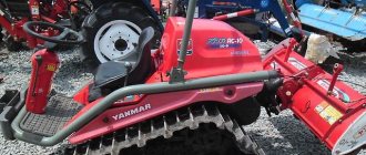
Self-propelled chassis device
The tractor structure has a characteristic, easily recognizable appearance.
The design of the M16 was non-standard: the power engine was located behind the cabin, and the cabin itself was located behind the body. This allowed the driver to keep the entire work area and equipment in sight.
Due to the body located in front, the chassis was popularly nicknamed “The Beggar”, as visually it resembled an outstretched hand.
Cabin
In the first models of the self-propelled chassis, the driver's position was purely nominal; there was actually no cabin. Subsequently, to prevent the driver’s seat from tipping over, they began to install a metal frame, which was attached to the frame with rubber shock absorbers.
Later, the frame turned into a full-fledged transforming cabin. It was equipped with removable elements that could be easily removed or added depending on weather conditions: roof, doors, window panels. The cabin also provided protection from mechanical damage and exhaust gases.
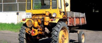
T-16 in operation with additional attachments
Maintenance
The advantage of this model is the fact that maintenance can be carried out independently, it is not complicated and high-cost.
Even after many years of operation, the M16 is repairable; the cost of work will be low. The only difficulty at the moment can be considered to be the reduction in the production of spare parts for this model or their absence.
The working life of all structures and equipment remains one of the highest, wear is considered low.
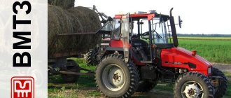
Modifications of T-16
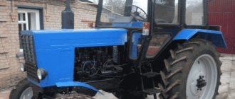
Later modifications of the self-propelled chassis are T-16M and T-16MG.
The engine power of both vehicles was already 25 hp, which improved the technical characteristics of the self-propelled chassis.
The T-16M, produced from 1967 to 1995, was able to reach a maximum speed of up to 23 km/h, and the minimum speed dropped to 1.5 km/h due to the creeper. This made it possible to make the tractor the most popular in the agricultural sector, as the range of work it carries out has increased. The cabin of this model, although it remained frame, was better equipped.
Modification of the T-16M self-propelled chassis
The T-16MG, which was produced from 1986 to 1995, received an improved engine. It made it possible to increase the speed to 40 km/h and use the power of the secondary school more efficiently.
Three power take-off shafts made the machine an absolute leader in working with suspended equipment: the design included two synchronous and one independent.
The improvement also affected the cabin - it became all-metal and allowed drivers to work with greater comfort.
Design and principle of operation of the T-16, T-25 generator
The direct current generator G96.3701 , installed on the T-16 and T-25 tractors , is necessary to supply electricity to consumers and to charge the unit’s battery. Two ball bearings are installed in the front and rear covers of the generator, in which the armature rotates.
The back cover is made with two brush holders mounted on it. The negative brush, installed in a non-insulated brush holder, is connected to the generator ground. The positive brush, installed in a brush holder, which is isolated from the generator body, is connected to the output terminal “I”. The brushes are pressed against the armature commutator under the influence of leaf springs.
One end of the generator excitation winding is connected to the output terminal “Ш”, and the other end of the winding is connected to the generator ground. Terminals “W” and “I” are connected by wires to the same terminals located on the relay regulator. In addition to the indicated terminals, the housing of the G96.3701 generator has a screw marked with the letter “M”. Its purpose is to secure the wire that connects the generator housing and the relay-regulator housing. Access to the brushes and commutator is provided through special windows made in the generator housing and covered with protective tape. The ball bearings are lubricated through oil nipples screwed into the generator covers.
The T-16, T-25 generator is mounted on a special bracket mounted on the left side of the diesel crankcase. The G96.3701 generator receives its drive through a V-belt drive through pulleys from the engine crankshaft. The generator drive pulley is pressed onto the front end of the armature shaft. The drive belt tension is adjusted by rotating the generator relative to the mounting bracket using a push bolt and lever.
The regulator, which is installed on the left wing of the chassis, automatically turns the generator on to the electrical network, maintains a constant voltage in the network, and also protects the generator from overloads. The relay regulator includes three electromagnetic devices - a reverse current relay, a voltage regulator and a current limiter. All three elements are installed on a common panel and covered by one protective casing.
The relay regulator is equipped with three terminals or clamps marked “B” (battery), “I” (armature) and “Sh” (shunt). The armature and shunt terminals are connected by wires to terminals of the same name on the generator, and the battery terminal, through an ammeter and fuse, is connected to the tractor battery and to current consumers. The “M” screw, located on the relay-regulator housing, is connected by wire to the “M” screw, which is located on the generator housing.
recommended products
Top sales
Generator T-16, T-25 (14V/1kW) G96.3701
In stock
Generator T-16, T-25 (14V/0.7kW) G466.3701
In stock